check engine VOLKSWAGEN JETTA 1998 Service Manual
[x] Cancel search | Manufacturer: VOLKSWAGEN, Model Year: 1998, Model line: JETTA, Model: VOLKSWAGEN JETTA 1998Pages: 339, PDF Size: 2.35 MB
Page 154 of 339
Downloaded from www.Manualslib.com manuals search engine 01-149
Repair Manual,
Brake System, Repair
Group 47; Assembly
overview: Brake
booster/brake master
cylinder for vehicles
with
ABS/EDL/ASR/ESP 7 -
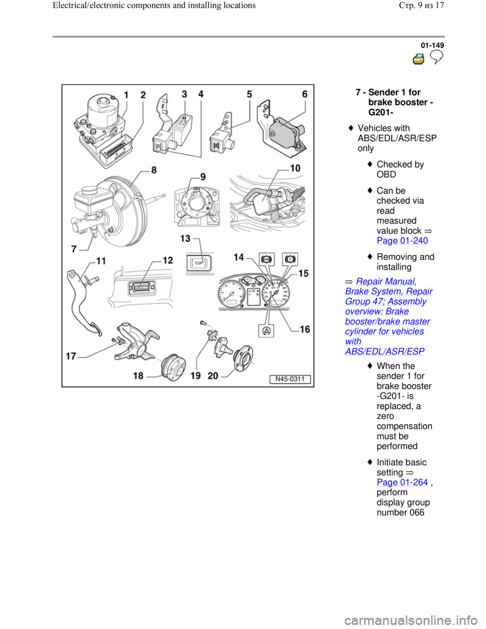
Sender 1 for
brake booster -
G201-
Vehicles with
ABS/EDL/ASR/ESP
only
Checked by
OBD
Can be
checked via
read
measured
value block
Page 01
-240
Removing and
installing
When the
sender 1 for
brake booster
-G201- is
replaced, a
zero
compensation
must be
performed
Initiate basic
setting
Page 01
-264 ,
perform
display group
number 066
Стр. 9из 17 Electrical/electronic components and installing locations
Page 155 of 339
Downloaded from www.Manualslib.com manuals search engine 01-150
Repair Manual,
Brake System, Repair
Group 45; Removing
and installing parts of
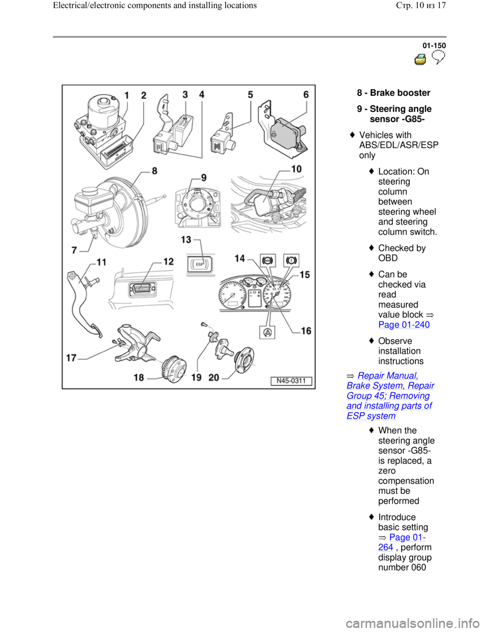
ESP system 8 -
Brake booster
9 -
Steering angle
sensor -G85-
Vehicles with
ABS/EDL/ASR/ESP
only
Location: On
steering
column
between
steering wheel
and steering
column switch.
Checked by
OBD
Can be
checked via
read
measured
value block
Page 01
-240
Observe
installation
instructions
When the
steering angle
sensor -G85-
is replaced, a
zero
compensation
must be
performed
Introduce
basic setting
Page 01
-
264 , perform
display group
number 060
Стр. 10из 17 Electrical/electronic components and installing locations
Page 156 of 339
Downloaded from www.Manualslib.com manuals search engine 01-151
Repair Manual,
Brake System,
Repair Group 47;
Brake system
vacuum pump -V192
Repair Manual,
Brake System,
Repair Group 47;
Brake system
vacuum pump -V192
Repair Manual,
Brake System,
Repair Group 46;
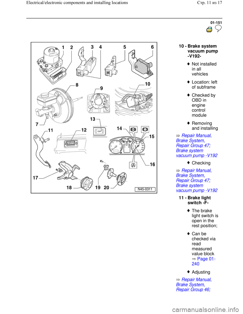
10 -
Brake system
vacuum pump
-V192-
Not installed
in all
vehicles
Location: left
of subframe
Checked by
OBD in
engine
control
module
Removing
and installing
Checking
11 -
Brake light
switch -F-
The brake
light switch is
open in the
rest position;
Can be
checked via
read
measured
value block
Page 01
-
240
Adjusting
Стр. 11из 17 Electrical/electronic components and installing locations
Page 159 of 339
Downloaded from www.Manualslib.com manuals search engine 01-153
Repair Manual,
Suspension, Wheels,
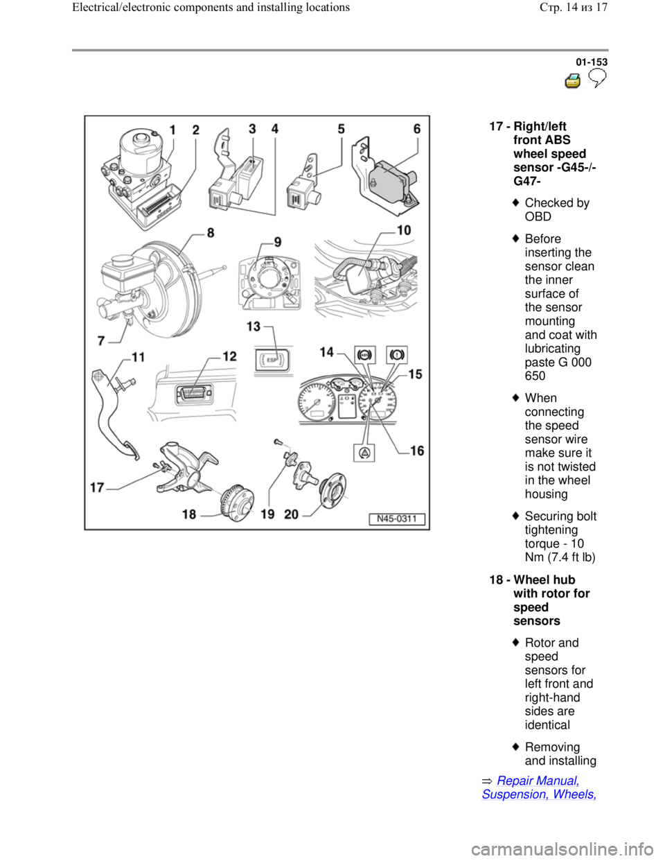
17 -
Right/left
front ABS
wheel speed
sensor -G45-/-
G47-
Checked by
OBD
Before
inserting the
sensor clean
the inner
surface of
the sensor
mounting
and coat with
lubricating
paste G 000
650
When
connecting
the speed
sensor wire
make sure it
is not twisted
in the wheel
housing
Securing bolt
tightening
torque - 10
Nm (7.4 ft lb)
18 -
Wheel hub
with rotor for
speed
sensors
Rotor and
speed
sensors for
left front and
right-hand
sides are
identical
Removing
and installing
Стр. 14из 17 Electrical/electronic components and installing locations
Page 161 of 339
Downloaded from www.Manualslib.com manuals search engine 01-154
Repair Manual,
Suspension, Wheels,
Steering, Repair
Group 42; Servicing
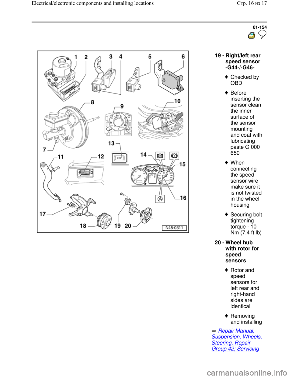
19 -
Right/left rear
speed sensor
-G44-/-G46-
Checked by
OBD
Before
inserting the
sensor clean
the inner
surface of
the sensor
mounting
and coat with
lubricating
paste G 000
650
When
connecting
the speed
sensor wire
make sure it
is not twisted
in the wheel
housing
Securing bolt
tightening
torque - 10
Nm (7.4 ft lb)
20 -
Wheel hub
with rotor for
speed
sensors
Rotor and
speed
sensors for
left rear and
right-hand
sides are
identical
Removing
and installing
Стр. 16из 17 Electrical/electronic components and installing locations
Page 167 of 339
Downloaded from www.Manualslib.com manuals search engine 01-159
On Board Diagnostic (OBD),
performing
Test prerequisites for OBD
The tires installed to all wheels must be of
the same (approved) size; tires inflated to
prescribed pressure.
Mechanical/hydraulic parts of the brake
system including brake light switch and
brake lights OK.
Hydraulic lines and connections not leaking
(visual check of hydraulic unit, brake
calipers, wheel cylinders, tandem master
brake cylinder).
ABS Control Module (w/EDL) -J104- is
correctly bolted to ABS Hydraulic Unit -
N55-.
Connector on ABS Control Module (w/EDL)
-J104- correctly plugged-in (retainer is
engaged).
Check contacts of ABS components for
damage and correct seating.
All fuses according to wiring diagram OK
(remove fuse from fuse holder to check).
Supply voltage OK (at least 10.0 V).
Стр. 1из 129 On Board Diagnostic (OBD), performing
Page 168 of 339
Downloaded from www.Manualslib.com manuals search engine 01-160
Access to the OBD is only possible when the
vehicle is stationary and ignition turned on
(or engine running).
Wheel bearings and wheel bearing play are
OK.
When checking the ABS system make sure
that the vehicle electric system is not
affected by electro-magnetic interference,
i.e. the vehicle is kept away from equipment
with a high current draw, e.g. from an electric
welding module.
Safety precautions
WARNING!
You must always secure testing and
measuring equipment on the rear seat.
When vehicle is being driven, a second
technician must operate this equipment.
Стр. 2из 129 On Board Diagnostic (OBD), performing
Page 169 of 339
Downloaded from www.Manualslib.com manuals search engine 01-161
Scan tool, connecting
All functions which could previously be
performed with V.A.G 1551/1552 can also
be performed with the new tester VAS 5051
in the operating mode vehicle OBD.
Operating instructions for Vehicle
Diagnosis, Testing and Information System
VAS 5051.
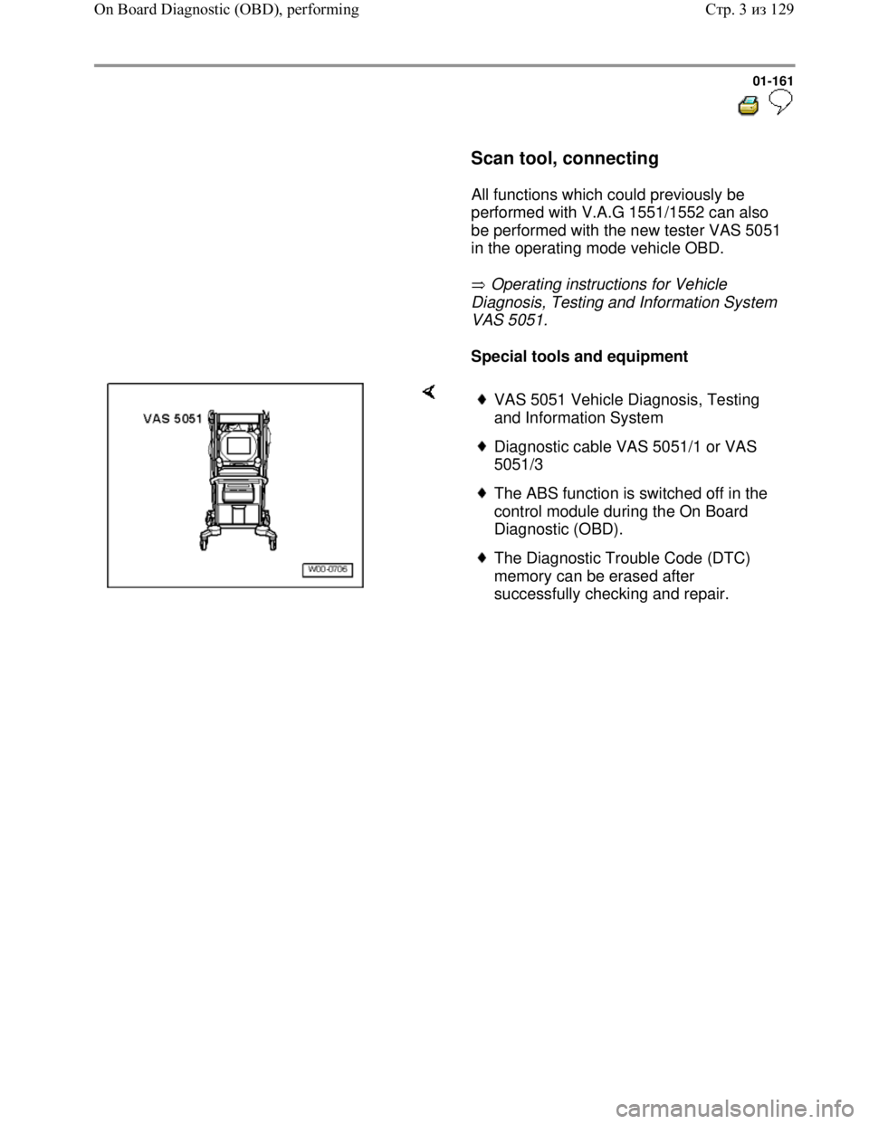
Special tools and equipment
VAS 5051 Vehicle Diagnosis, Testing
and Information System
Diagnostic cable VAS 5051/1 or VAS
5051/3
The ABS function is switched off in the
control module during the On Board
Diagnostic (OBD).
The Diagnostic Trouble Code (DTC)
memory can be erased after
successfully checking and repair.
Стр. 3из 129 On Board Diagnostic (OBD), performing
Page 172 of 339
Downloaded from www.Manualslib.com manuals search engine 01-164
Note:
The ABS function is switched off in the control
module during the OBD. This is indicated by th
e
flashing of ABS warning light -K47- and warning
light for brake system -K118-. If there is a
malfunction currently, it will be indicated by the
lights being on constantly.
The DTC memory can be erased after
successful check and repair.
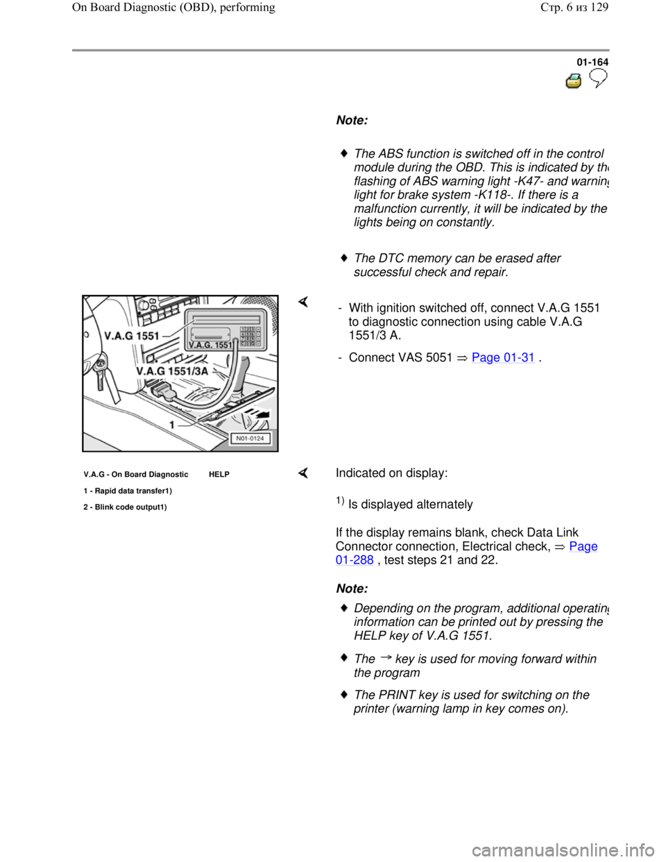
- With ignition switched off, connect V.A.G 1551
to diagnostic connection using cable V.A.G
1551/3 A.
- Connect VAS 5051 Page 01
-31 .
V.A.G - On Board Diagnostic HELP
1 - Ra
pid data transfer1)
2 - Blink code output1)
Indicated on display:
1) Is displayed alternately
If the display remains blank, check Data Link
Connector connection, Electrical check, Page
01-288 , test steps 21 and 22.
Note:
Depending on the program, additional operating
information can be printed out by pressing the
HELP key of V.A.G 1551.
The key is used for moving forward within
the program
The PRINT key is used for switching on the
printer (warning lamp in key comes on).
Стр. 6из 129 On Board Diagnostic (OBD), performing
Page 175 of 339
Downloaded from www.Manualslib.com manuals search engine 01-167
If "control module does not answer!" again
appears:
Rapid data transfer HELP
control module does not answer! Indicated on display:
- Perform test steps 1, 2 and 3 Page
01-288 , Electrical check.
Rapid data transfer
No signal from control module!
Control module identification influenced
during checking (possibly influenced from
external sources?)
- Check diagnostic wire as well as voltage
supply and Ground connection for ABS
Control Module (w/EDL) -J104-,
Electrical check, Page 01
-288 .
- After repairing the possible causes of the
malfunction, again enter the address
word 03 for "Brake electronics" and
confirm with Q key.
Стр. 9из 129 On Board Diagnostic (OBD), performing