VOLKSWAGEN JETTA 1998 Service Manual
Manufacturer: VOLKSWAGEN, Model Year: 1998, Model line: JETTA, Model: VOLKSWAGEN JETTA 1998Pages: 339, PDF Size: 2.35 MB
Page 1 of 339
Downloaded from www.Manualslib.com manuals search engine
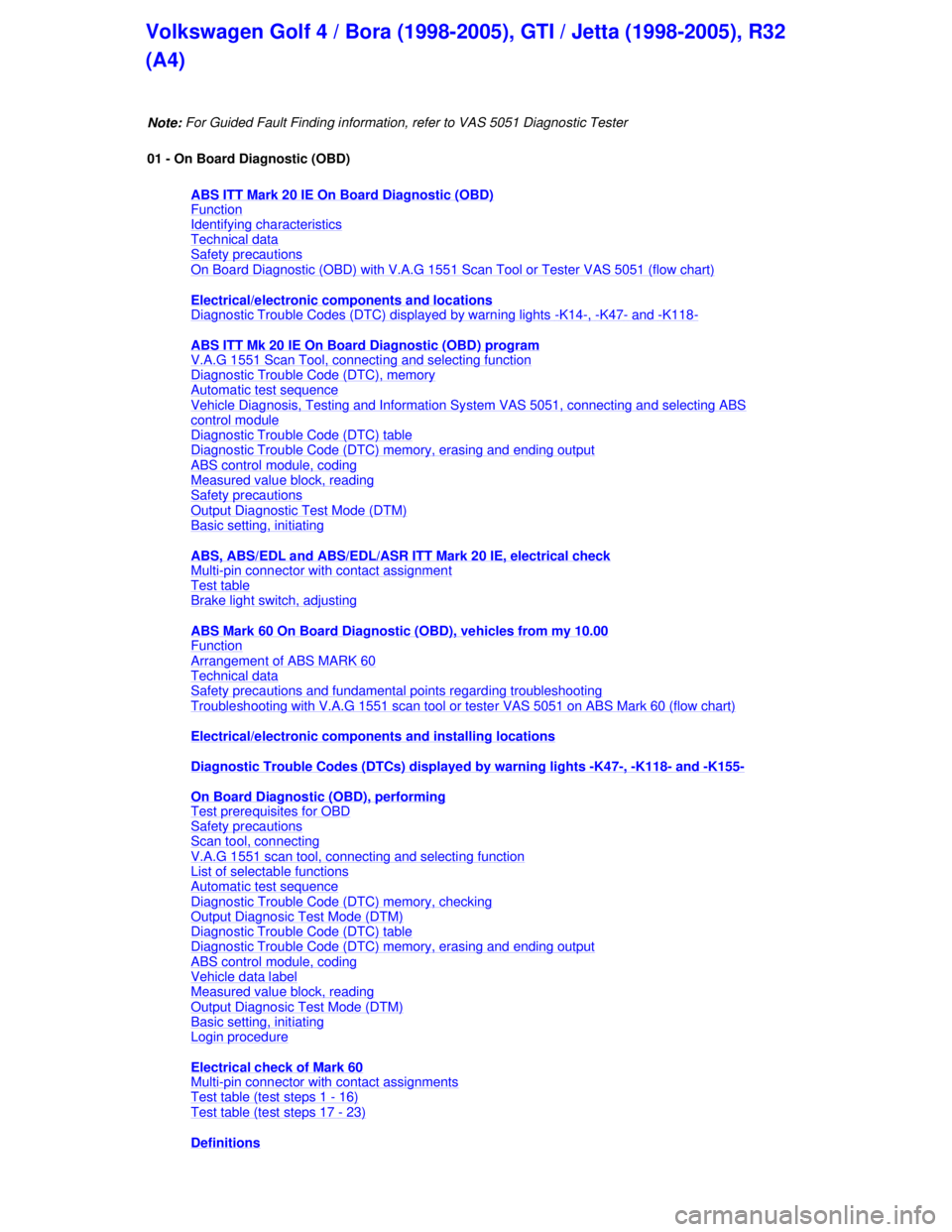
Note: For Guided Fault Finding information,
refer to VAS 5051 Diagnostic Tester
01 - On Board Diagnostic (OBD)
ABS ITT Mark 20 IE On Board Diagnostic (OBD)
Function
Identifying characteristics
Technical data
Safety precautions
On Board Diagnostic (OBD) with V.A.G 1551 Scan Tool or Tester VAS 5051 (flow chart)
Electrical/electronic co mponents and locations
Diagnostic Trouble Codes (DTC) displayed by warning lights
-K14-, -K47- and -K118-
ABS ITT Mk 20 IE On Board Diagnostic (OBD) program
V.A.G 1551 Scan Tool, connecting and selecting function
Diagnostic Trouble Code (DTC), memory
Automatic test sequence
Vehicle Diagnosis, Testing and Information Sy stem VAS 5051, connecting and selecting ABS
control module
Diagnostic Trouble Code (DTC) table
Diagnostic Trouble Code (DTC) memory, erasing and ending output
ABS control module, coding
Measured value block, reading
Safety precautions
Output Diagnostic Test Mode (DTM)
Basic setting, initiating
ABS, ABS/EDL and ABS/EDL/ASR IT T Mark 20 IE, electrical check
Multi
-pin connector with contact assignment
Test table
Brake light switch, adjusting
ABS Mark 60 On Board Diagnostic (OBD), vehicles from my 10.00
Function
Arrangement of ABS MARK 60
Technical data
Safety precautions and fundamental points regarding troubleshooting
Troubleshooting with V.A.G 1551 scan tool or tester VAS 5051 on ABS Mark 60 (flow chart)
Electrical/electronic compon ents and installing locations
Diagnostic Trouble Codes (DTCs) displayed by warning lights
-K47-, -K118- and -K155-
On Board Diagnostic (OBD), performing
Test prerequisites for OBD
Safety precautions
Scan tool, connecting
V.A.G 1551 scan tool, connecting and selecting function
List of selectable functions
Automatic test sequence
Diagnostic Trouble Code (DTC) memory, checking
Output Diagnosic Test Mode (DTM)
Diagnostic Trouble Code (DTC) table
Diagnostic Trouble Code (DTC) memory, erasing and ending output
ABS control module, coding
Vehicle data label
Measured value block, reading
Output Diagnosic Test Mode (DTM)
Basic setting, initiating
Login procedure
Electrical check of Mark 60
Multi
-pin connector with contact assignments
Test table (test steps 1
- 16)
Test table (test steps 17
- 23)
Definitions
Volkswagen Golf 4 / Bora (1998-2005), GTI / Jetta (1998-2005), R32
(A4)
Page 2 of 339
Downloaded from www.Manualslib.com manuals search engine 01-1
ABS ITT Mark 20 IE On Board
Diagnostic (OBD)
Function
Since the control modules are interconnected
with CAN-bus, always begin OBD by checking
the Diagnostic Trouble Code (DTC) memories
of all the control modules in the vehicle.
This occurs in the Automatic test sequence and
is activated with key function 00.
When doing this, check to see if there are
DTCs stored which may influence the ABS.
On Board Diagnostic (OBD) relates to the
electrical/electronic part of the ABS, i.e. only
malfunctions via the electrical connection to the
control module are recognized (e.g. speed
sensor open circuit).
The 25-pin ABS Control Module (w/EDL) -J104-
forms with the hydraulic unit a compact unit.
The unit is located on the left in the engine
compartment. The control module is equipped
with a DTC memory. The diagnostic connection
is located in the center console below the
heating/air conditioning controls.
The control module recognizes malfunctions
during vehicle operation and stores them in a
permanent memory, the contents of which
remain even during periods of no battery
voltage.
Стр. 1из 8 ABS ITT Mark 20 IE On Board Diagnostic (OBD)
Page 3 of 339
Downloaded from www.Manualslib.com manuals search engine 01-2
Sporadic (isolated) malfunctions will also be
recognized and stored. But if these malfunctions
do not occur again within the next 50 vehicle
starts and driving off sequences then, with the
exception of "control module inoperative", the
DTC memory will be erased.
After switching on the ignition and/or starting the
engine the ABS warning light -K47- and the
warning light for brake system -K118- light up for
approx. 2 seconds.
During this period a test sequence (self-check) is
run in the control module for the following
functions:
To check if the supply voltage is at least 10.0
Volt
To check control module including the valve
windings
To check the coding of the control module
A static check of the speed sensor (no speed
signal)
If after driving off and exceeding a speed of
approx. 20 km/h (approx. 13 mph) the speed
signal is not OK. The ABS warning light -K47-
will light up again.
Стр. 2из 8 ABS ITT Mark 20 IE On Board Diagnostic (OBD)
Page 4 of 339
Downloaded from www.Manualslib.com manuals search engine 01-3
V.A.G 1551 Scan Tool or tester VAS 5051
The On Board Diagnostic (OBD) must be
initiated always at the commencement of
troubleshooting. Electrical malfunctions which
influence the braking characteristics will be
stored. They can be checked with the V.A.G
1551 Scan Tool or with the tester VAS 5051.
The information displayed is used in
conjunction with a DTC table which has
information on the possible DTC causes for
repair measures.
Стр. 3из 8 ABS ITT Mark 20 IE On Board Diagnostic (OBD)
Page 5 of 339
Downloaded from www.Manualslib.com manuals search engine 01-4
Identifying characteristics
The brake booster boost is produced by
vacuum pressure.
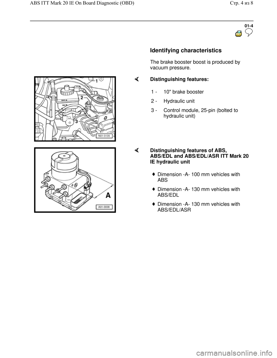
Distinguishing features:
1 - 10" brake booster
2 - Hydraulic unit
3 - Control module, 25-pin (bolted to
hydraulic unit)
Distinguishing features of ABS,
ABS/EDL and ABS/EDL/ASR ITT Mark 20
IE hydraulic unit
Dimension -A- 100 mm vehicles with
ABS
Dimension -A- 130 mm vehicles with
ABS/EDL
Dimension -A- 130 mm vehicles with
ABS/EDL/ASR
Стр. 4из 8 ABS ITT Mark 20 IE On Board Diagnostic (OBD)
Page 6 of 339
Downloaded from www.Manualslib.com manuals search engine 01-5
Technical data
Control module identification
The control module version is displayed when
the V.A.G 1551 Scan Tool or the tester VAS
5051 is connected and the control module for
brake electronics is selected Page 01
-23 .
1J0 907 379 D / G - ABS
1J0 907 379 E / H - ABS/EDL
1J0 907 379 R / J - ABS/EDL/ASR
Diagnostic Trouble Code (DTC) memory
A non-volatile memory ensures that the
contents of the DTC memory are retained even
without a voltage supply.
Data outputis achieved in operating mode 1
(rapid data transfer).
Стр. 5из 8 ABS ITT Mark 20 IE On Board Diagnostic (OBD)
Page 7 of 339
Downloaded from www.Manualslib.com manuals search engine 01-6
Safety precautions
The ABS is a vehicle safety system; the
appropriate knowledge is necessary to work on
the system.
In order to check complaints and to be able to
carry out pin-pointed troubleshooting, the
Diagnostic Trouble Code (DTC) memory must
be checked before beginning work on the ABS
system.
Only separate connectors when the ignition is
switched off.
Observe the appropriate instructions regarding
the handling of brake fluid.
Repair Manual, Brake System, Repair Group
47
ABS malfunctions are indicated by the ABS
warning light illuminating. Certain malfunctions
will only be recognized at speeds above 20
km/h (approx. 13 mph) (carry out road test).
If the ABS Warning Light -K47- and the warning
light for brake system -K118- do not light up,
but the brake system is not functioning correctly
then the malfunction must be sought in the
conventional braking system.
Repair Manual, Brake System; Repair Group
45
Стр. 6из 8 ABS ITT Mark 20 IE On Board Diagnostic (OBD)
Page 8 of 339
Downloaded from www.Manualslib.com manuals search engine 01-7
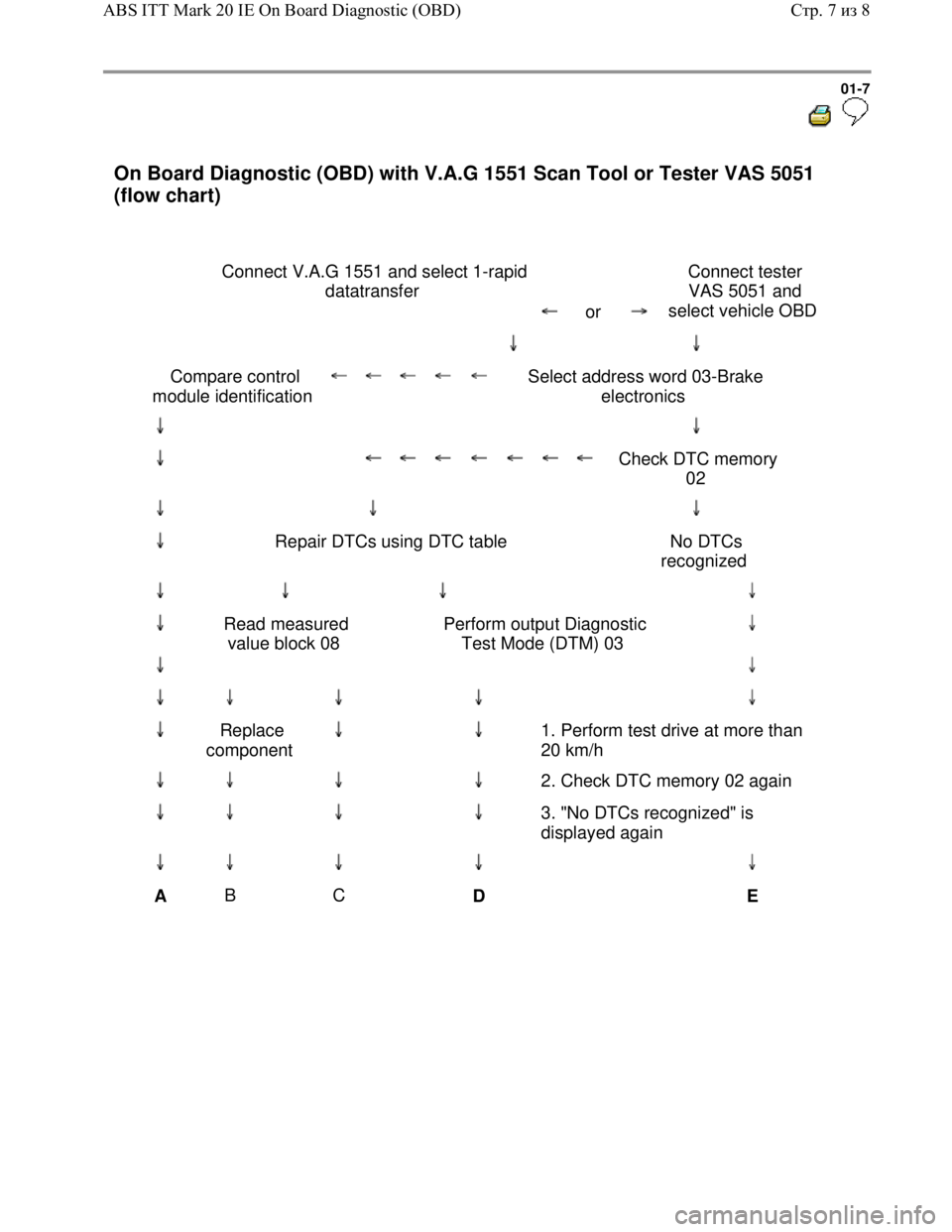
On Board Diagnostic (OBD) with V.A.G 1551 Scan Tool or Tester VAS 5051
(flow chart)
Connect V.A.G 1551 and select 1-rapid
datatransfer
or
Connect tester
VAS 5051 and
select vehicle OBD
Compare control
module identification
Select address word 03-Brake
electronics
Check DTC memory
02
Repair DTCs using DTC table No DTCs
recognized
Read measured
value block 08 Perform output Diagnostic
Test Mode (DTM) 03
Replace
component
1. Perform test drive at more than
20 km/h
2. Check DTC memory 02 again
3. "No DTCs recognized" is
displayed again
A B
C
D
E
Стр. 7из 8 ABS ITT Mark 20 IE On Board Diagnostic (OBD)
Page 9 of 339
Downloaded from www.Manualslib.com manuals search engine 01-8
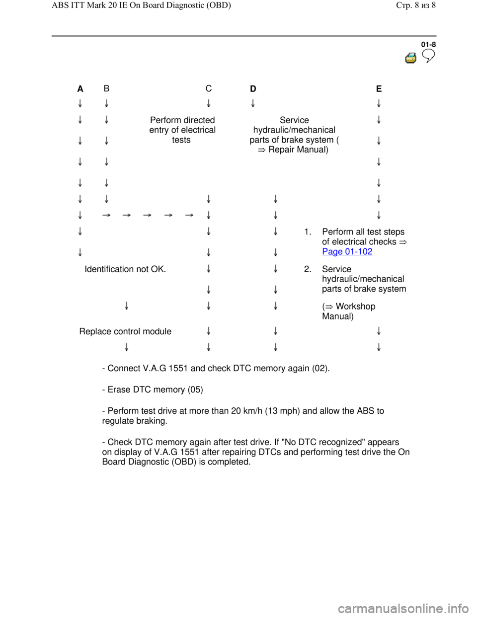
A B
C
D
E
Perform directed
entry of electrical
tests Service
hydraulic/mechanical
parts of brake system (
Repair Manual)
1. Perform all test steps
of electrical checks
Page 01
-102
Identification not OK.
2. Service
hydraulic/mechanical
parts of brake system
( Workshop
Manual)
Replace control module
- Connect V.A.G 1551 and check DTC memory again (02).
- Erase DTC memory (05)
- Perform test drive at more than 20 km/h (13 mph) and allow the ABS to
regulate braking.
- Check DTC memory again after test drive. If "No DTC recognized" appears
on display of V.A.G 1551 after repairing DTCs and performing test drive the On
Board Diagnostic (OBD) is completed.
Стр. 8из 8 ABS ITT Mark 20 IE On Board Diagnostic (OBD)
Page 10 of 339
Downloaded from www.Manualslib.com manuals search engine
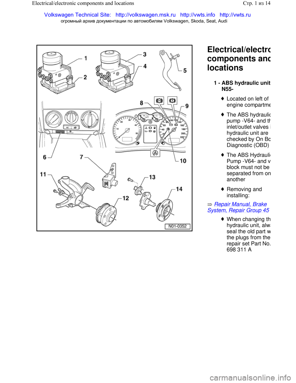
Electrical/electro
components and
locations
Repair Manual, Brake
System, Repair Group 45
1 -
ABS hydraulic unit
N55-
Located on left of
engine compartm
e
The ABS hydraulic
pump -V64- and th
inlet/outlet valves i
hydraulic unit are
checked by On B
o
Diagnostic (OBD)
The ABS Hydraulic
Pump -V64- and v
block must not be
separated from o
n
another
Removing and
installing:
When changing th
hydraulic unit, alw
a
seal the old part w
the plugs from the
repair set Part No.
698 311 A
Стр. 1 из 14
Electrical/electronic components and locations
Volkswagen Technical Site: http://v olkswagen.msk.ru http://vwts.info http://vwts.ru
огромный архив документации по автомобилям Volkswagen, Skoda, Seat, Audi