check engine VOLKSWAGEN JETTA 1998 Service Manual
[x] Cancel search | Manufacturer: VOLKSWAGEN, Model Year: 1998, Model line: JETTA, Model: VOLKSWAGEN JETTA 1998Pages: 339, PDF Size: 2.35 MB
Page 230 of 339
Downloaded from www.Manualslib.com manuals search engine 01-222
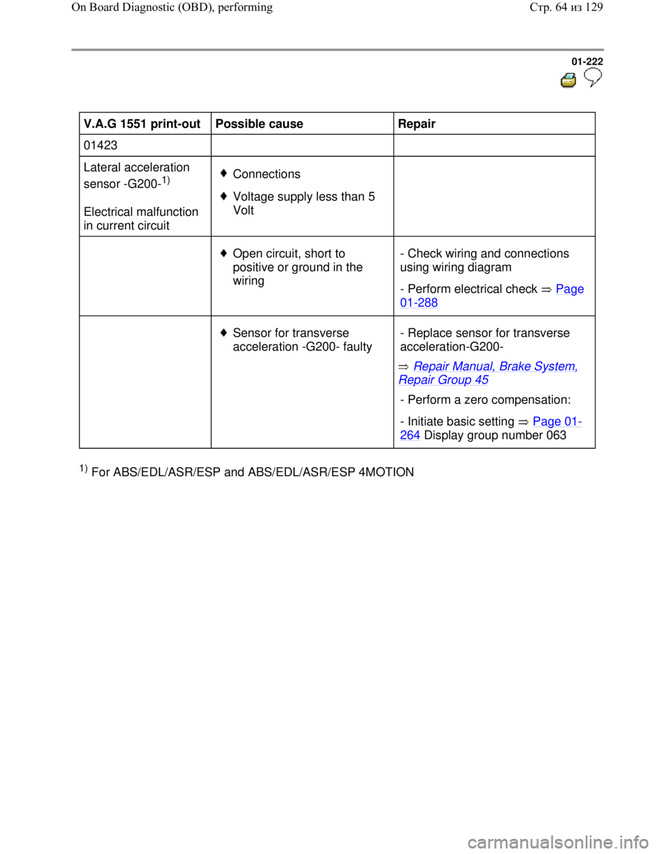
V.A.G 1551 print-out
Possible cause
Repair
01423
Lateral acceleration
sensor -G200-
1)
Electrical malfunction
in current circuit Connections
Voltage supply less than 5
Volt
Open circuit, short to
positive or ground in the
wiring - Check wiring and connections
using wiring diagram
- Perform electrical check Page
01-288
Sensor for transverse
acceleration -G200- faulty
Repair Manual, Brake System,
Repair Group 45 - Replace sensor for transverse
acceleration-G200-
- Perform a zero compensation:
- Initiate basic setting Page 01
-
264 Display group number 063
1) For ABS/EDL/ASR/ESP and ABS/EDL/ASR/ESP 4MOTION
Стр. 64из 129 On Board Diagnostic (OBD), performing
Page 231 of 339
Downloaded from www.Manualslib.com manuals search engine 01-223
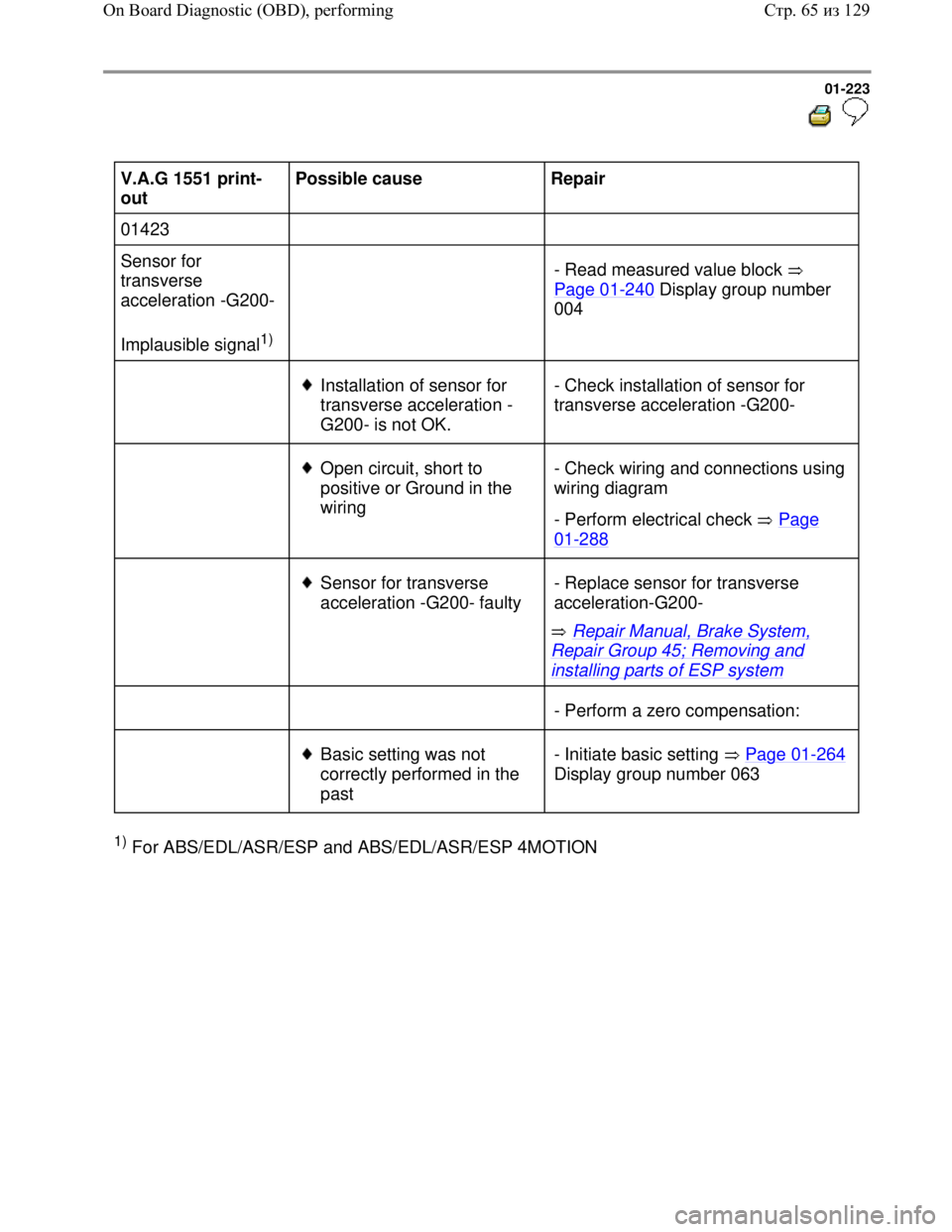
V.A.G 1551 print-
out Possible cause
Repair
01423
Sensor for
transverse
acceleration -G200-
Implausible signal
1)
- Read measured value block
Page 01
-240 Display group number
004
Installation of sensor for
transverse acceleration -
G200- is not OK. - Check installation of sensor for
transverse acceleration -G200-
Open circuit, short to
positive or Ground in the
wiring - Check wiring and connections using
wiring diagram
- Perform electrical check Page
01-288
Sensor for transverse
acceleration -G200- faulty
Repair Manual, Brake System,
Repair Group 45; Removing and
installing parts of ESP system - Replace sensor for transverse
acceleration-G200-
- Perform a zero compensation:
Basic setting was not
correctly performed in the
past - Initiate basic setting Page 01-264
Display group number 063
1) For ABS/EDL/ASR/ESP and ABS/EDL/ASR/ESP 4MOTION
Стр. 65из 129 On Board Diagnostic (OBD), performing
Page 233 of 339
Downloaded from www.Manualslib.com manuals search engine 01-225
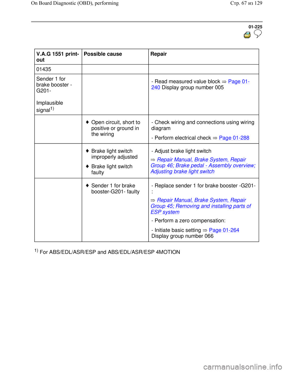
V.A.G 1551 print-
out Possible cause
Repair
01435
Sender 1 for
brake booster -
G201-
Implausible
signal
1)
- Read measured value block Page 01
-
240 Display group number 005
Open circuit, short to
positive or ground in
the wiring - Check wiring and connections using wiring
diagram
- Perform electrical check Page 01
-288
Brake light switch
improperly adjusted
Brake light switch
faulty Repair Manual, Brake System, Repair Group 46; Brake pedal - Assembly overview;
Adjusting brake light switch - Adjust brake light switch
Sender 1 for brake
booster-G201- faulty
Repair Manual, Brake System, Repair
Group 45; Removing and installing parts of
ESP system - Replace sender 1 for brake booster -G201-
:
- Perform a zero compensation:
- Initiate basic setting Page 01
-264
Display group number 066
1) For ABS/EDL/ASR/ESP and ABS/EDL/ASR/ESP 4MOTION
Стр. 67из 129 On Board Diagnostic (OBD), performing
Page 234 of 339
Downloaded from www.Manualslib.com manuals search engine
01-226
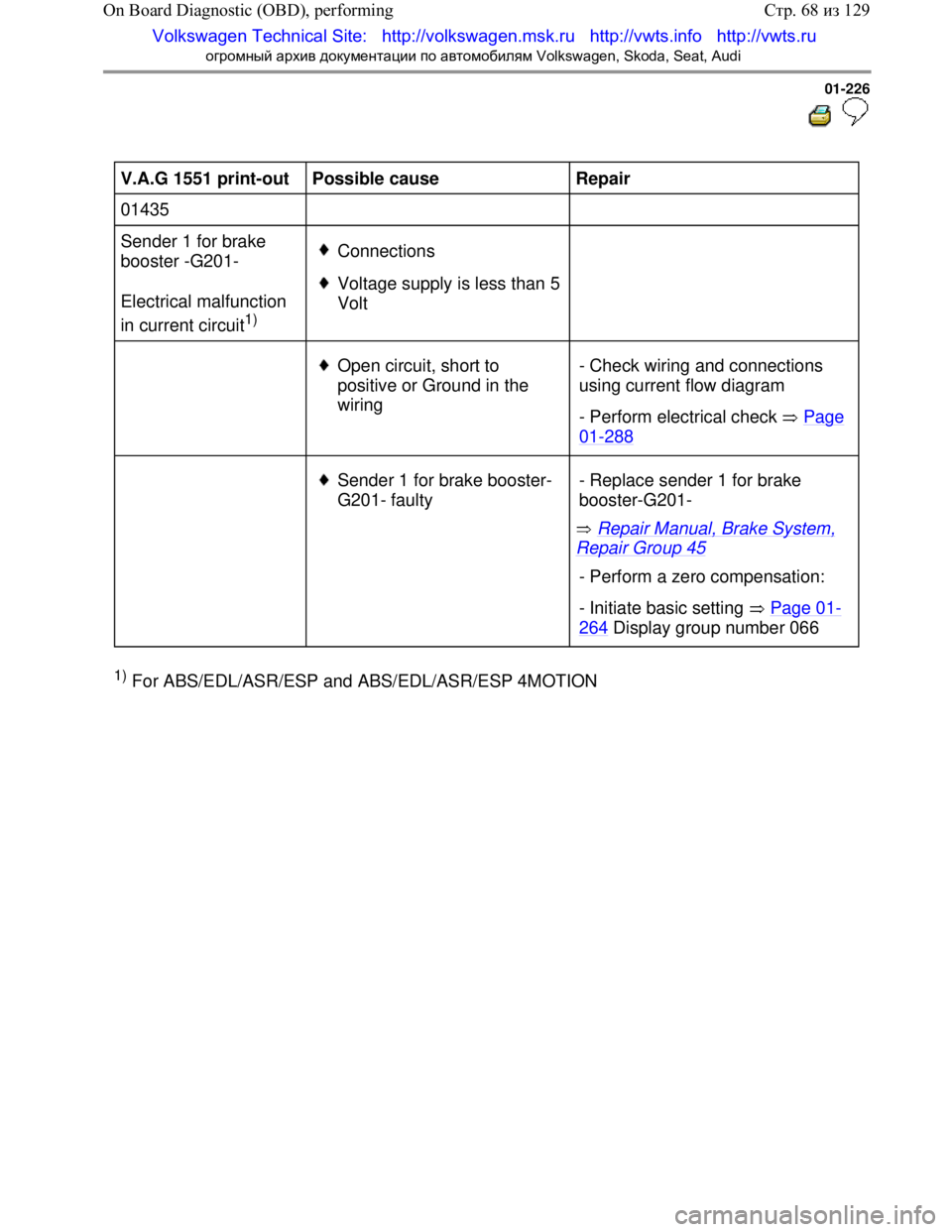
V.A.G 1551 print-out
Possible cause
Repair
01435
Sender 1 for brake
booster -G201-
Electrical malfunction
in current circuit
1)
Connections
Voltage supply is less than 5
Volt
Open circuit, short to
positive or Ground in the
wiring - Check wiring and connections
using current
flow diagram
- Perform electrical check Page
01-288
Sender 1 for brake booster-
G201- faulty
Repair Manual, Brake System,
Repair Group 45
- Replace sender 1 for brake
booster-G201-
- Perform a zero compensation:
- Initiate basic setting
Page 01
-
264 Display group number 066
1) For ABS/EDL/ASR/ESP an d ABS/EDL/ASR/ESP 4MOTION
Стр. 68
из 129
On Board Diagnostic (OBD), performing
Volkswagen Technical Site: http://v olkswagen.msk.ru http://vwts.info http://vwts.ru
огромный архив документации по автомобилям Volkswagen, Skoda, Seat, Audi
Page 236 of 339
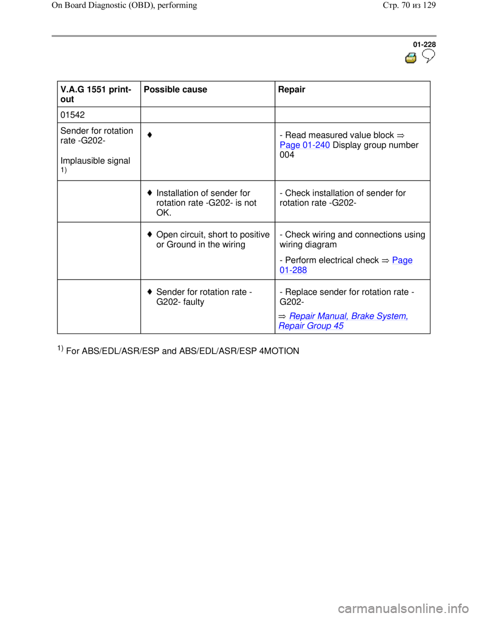
Downloaded from www.Manualslib.com manuals search engine 01-228
V.A.G 1551 print-
out Possible cause
Repair
01542
Sender for rotation
rate -G202-
Implausible signal
1)
- Read measured value block
Page 01
-240 Display group number
004
Installation of sender for
rotation rate -G202- is not
OK. - Check installation of sender for
rotation rate -G202-
Open circuit, short to positive
or Ground in the wiring - Check wiring and connections using
wiring diagram
- Perform electrical check Page
01-288
Sender for rotation rate -
G202- faulty
Repair Manual, Brake System,
Repair Group 45 - Replace sender for rotation rate -
G202-
1) For ABS/EDL/ASR/ESP and ABS/EDL/ASR/ESP 4MOTION
Стр. 70из 129 On Board Diagnostic (OBD), performing
Page 237 of 339
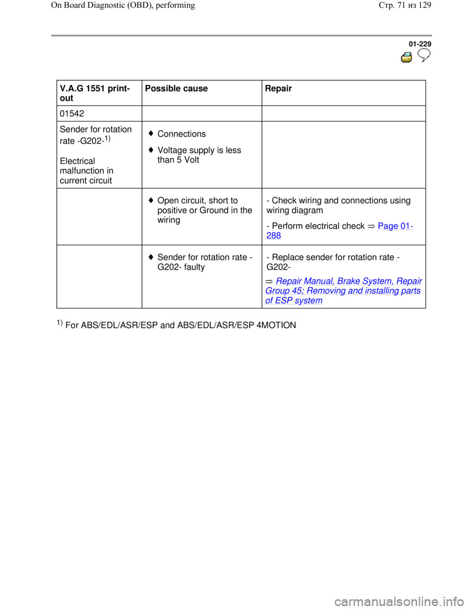
Downloaded from www.Manualslib.com manuals search engine 01-229
V.A.G 1551 print-
out Possible cause
Repair
01542
Sender for rotation
rate -G202-
1)
Electrical
malfunction in
current circuit Connections
Voltage supply is less
than 5 Volt
Open circuit, short to
positive or Ground in the
wiring - Check wiring and connections using
wiring diagram
- Perform electrical check Page 01
-
288
Sender for rotation rate -
G202- faulty
Repair Manual, Brake System, Repair
Group 45; Removing and installing parts
of ESP system - Replace sender for rotation rate -
G202-
1) For ABS/EDL/ASR/ESP and ABS/EDL/ASR/ESP 4MOTION
Стр. 71из 129 On Board Diagnostic (OBD), performing
Page 238 of 339
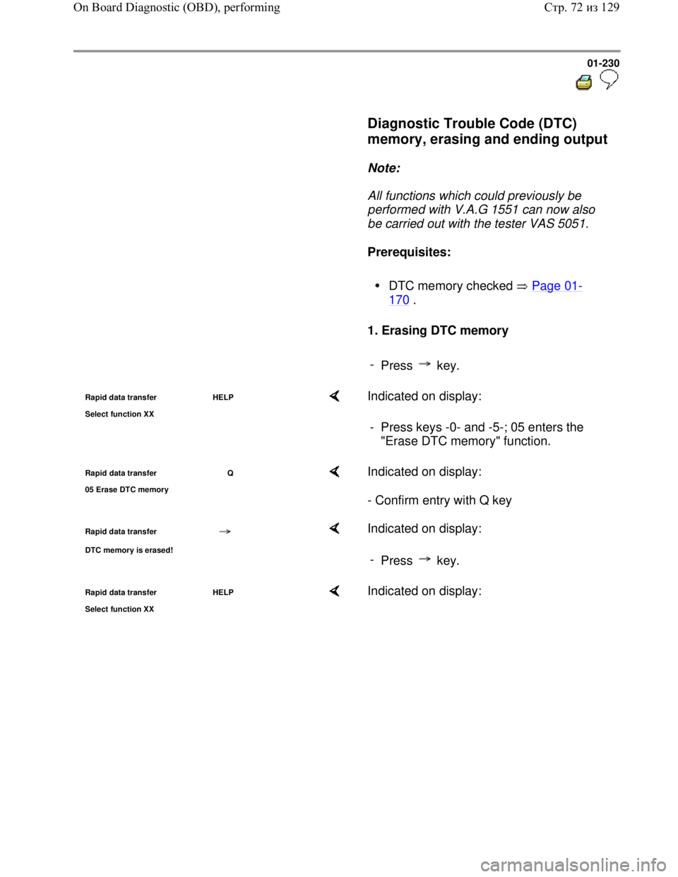
Downloaded from www.Manualslib.com manuals search engine 01-230
Diagnostic Trouble Code (DTC)
memory, erasing and ending output
Note:
All functions which could previously be
performed with V.A.G 1551 can now also
be carried out with the tester VAS 5051.
Prerequisites:
DTC memory checked Page 01-
170 .
1. Erasing DTC memory
-
Press key.
Rapid data transfer HELP
Select function XX Indicated on display:
- Press keys -0- and -5-; 05 enters the
"Erase DTC memory" function.
Rapid data transfer Q
05 Erase DTC memor
y
Indicated on display:
- Confirm entry with Q key
Rapid data transfer
DTC memory is erased!
Indicated on display:
-
Press key.
Rapid data transfer HELP
Select function XX Indicated on display:
Стр. 72из 129 On Board Diagnostic (OBD), performing
Page 239 of 339
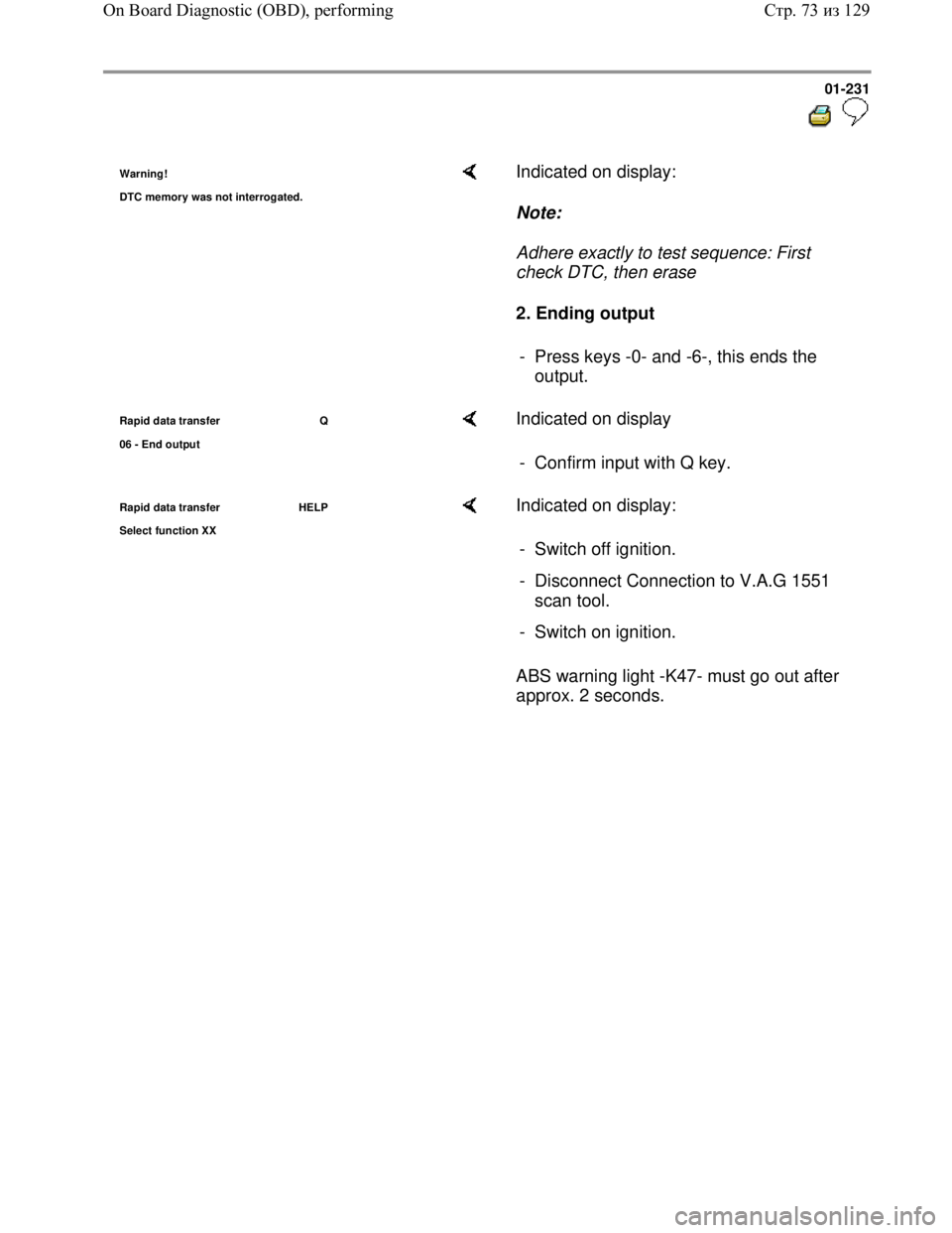
Downloaded from www.Manualslib.com manuals search engine 01-231
Warning!
DTC memor
y was not interrogated.
Indicated on display:
Note:
Adhere exactly to test sequence: First
check DTC, then erase
2. Ending output
- Press keys -0- and -6-, this ends the
output.
Rapid data transfer Q
06 - End out
put
Indicated on display
- Confirm input with Q key.
Rapid data transfer HELP
Select function XX Indicated on display:
ABS warning light -K47- must go out after
approx. 2 seconds. - Switch off ignition.
- Disconnect Connection to V.A.G 1551
scan tool.
- Switch on ignition.
Стр. 73из 129 On Board Diagnostic (OBD), performing
Page 253 of 339
Downloaded from www.Manualslib.com manuals search engine 01-245
Test sequence and test tables with
measured values
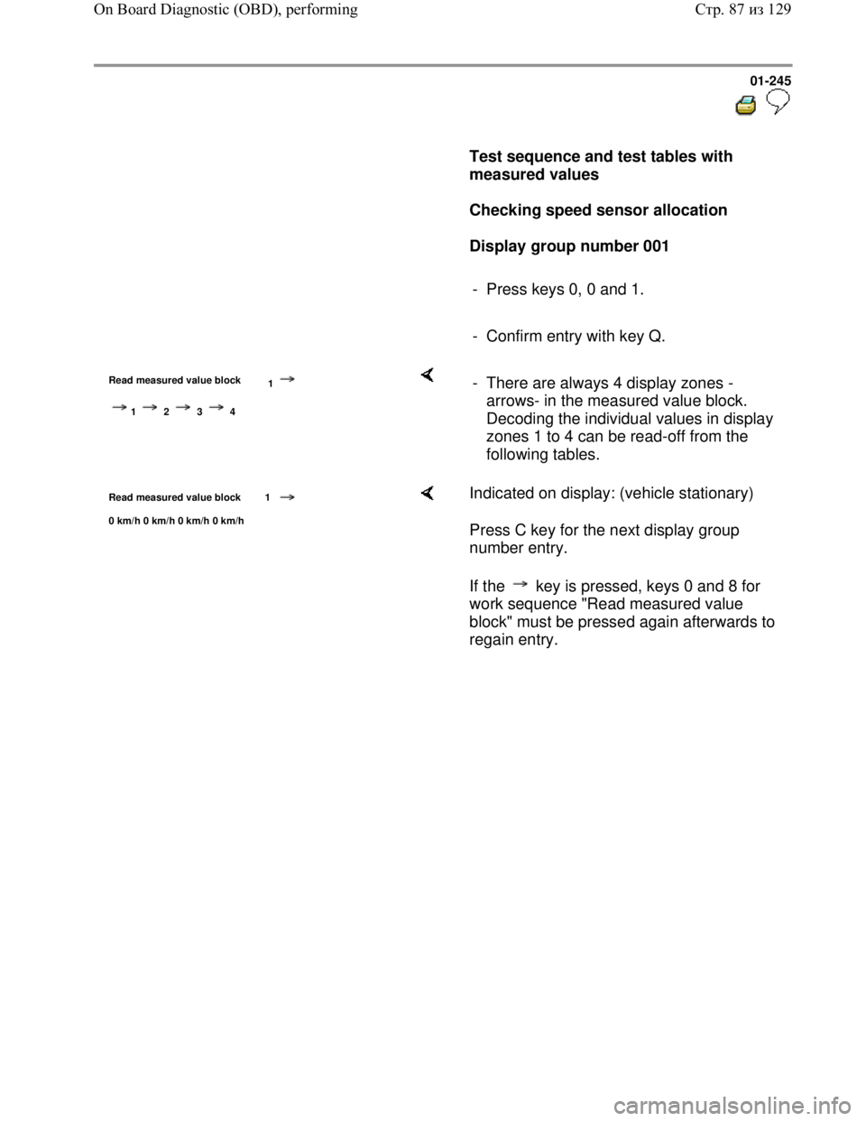
Checking speed sensor allocation
Display group number 001
- Press keys 0, 0 and 1.
- Confirm entry with key Q.
Read measured value block
1
1 2 3 4
- There are always 4 display zones -
arrows- in the measured value block.
Decoding the individual values in display
zones 1 to 4 can be read-off from the
following tables.
Read measured value block 1
0 km/h 0 km/h 0 km/h 0 km/h
Indicated on display: (vehicle stationary)
Press C key for the next display group
number entry.
If the key is pressed, keys 0 and 8 for
work sequence "Read measured value
block" must be pressed again afterwards to
regain entry.
Стр. 87из 129 On Board Diagnostic (OBD), performing
Page 254 of 339
Downloaded from www.Manualslib.com manuals search engine 01-246
Note:
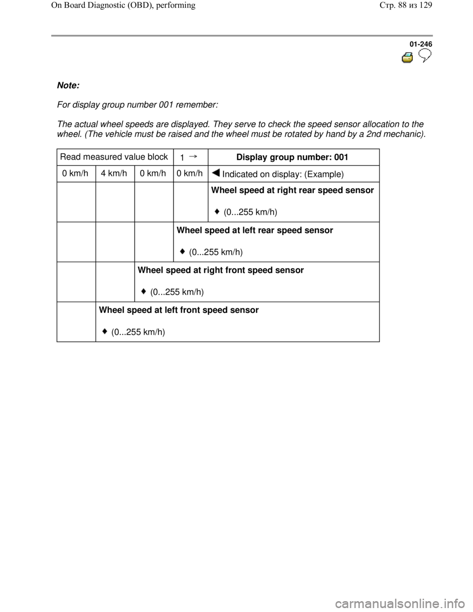
For display group number 001 remember:
The actual wheel speeds are displayed. They serve to check the speed sensor allocation to the
wheel. (The vehicle must be raised and the wheel must be rotated by hand by a 2nd mechanic).
Read measured value block
1 Display group number: 001
0 km/h 4 km/h 0 km/h 0 km/h
Indicated on display: (Example)
Wheel speed at right rear speed sensor
(0...255 km/h)
Wheel speed at left rear speed sensor
(0...255 km/h)
Wheel speed at right front speed sensor
(0...255 km/h)
Wheel speed at left front speed sensor
(0...255 km/h)
Стр. 88из 129 On Board Diagnostic (OBD), performing