steering VOLKSWAGEN JETTA 1998 Owner's Manual
[x] Cancel search | Manufacturer: VOLKSWAGEN, Model Year: 1998, Model line: JETTA, Model: VOLKSWAGEN JETTA 1998Pages: 339, PDF Size: 2.35 MB
Page 259 of 339
Downloaded from www.Manualslib.com manuals search engine 01-251
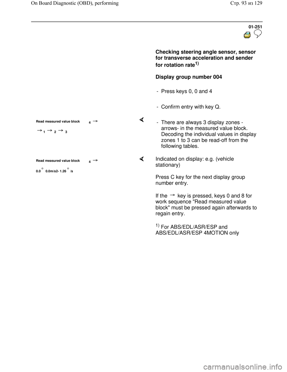
Checking steering angle sensor, sensor
for transverse acceleration and sender
for rotation rate
1)
Display group number 004
- Press keys 0, 0 and 4
- Confirm entry with key Q.
Read measured value block
4
1 2 3
- There are always 3 display zones -
arrows- in the measured value block.
Decoding the individual values in display
zones 1 to 3 can be read-off from the
following tables.
Read measured value block
4
0.0 0.0m/s2- 1.26/s
Indicated on display: e.g. (vehicle
stationary)
Press C key for the next display group
number entry.
If the key is pressed, keys 0 and 8 for
work sequence "Read measured value
block" must be pressed again afterwards to
regain entry.
1) For ABS/EDL/ASR/ESP and
ABS/EDL/ASR/ESP 4MOTION only
Стр. 93из 129 On Board Diagnostic (OBD), performing
Page 260 of 339
Downloaded from www.Manualslib.com manuals search engine 01-252
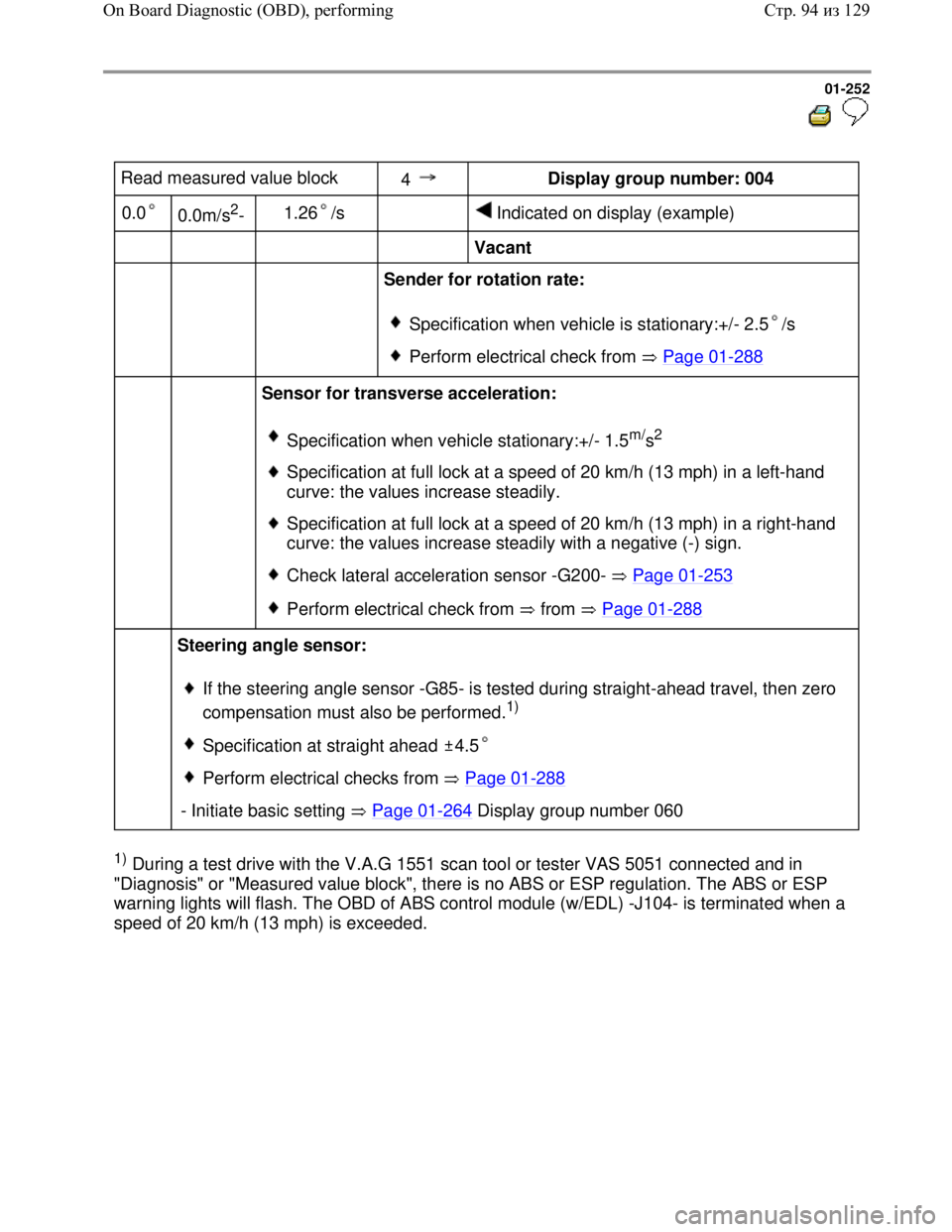
Read measured value block
4 Display group number: 004
0.0
0.0m/s2-
1.26 /s
Indicated on display (example)
Vacant
Sender for rotation rate:
Specification when vehicle is stationary:+/- 2.5 /s
Perform electrical check from Page 01-288
Sensor for transverse acceleration:
Specification when vehicle stationary:+/- 1.5m/s2
Specification at full lock at a speed of 20 km/h (13 mph) in a left-hand
curve: the values increase steadily.
Specification at full lock at a speed of 20 km/h (13 mph) in a right-hand
curve: the values increase steadily with a negative (-) sign.
Check lateral acceleration sensor -G200- Page 01-253
Perform electrical check from from Page 01-288
Steering angle sensor:
If the steering angle sensor -G85- is tested during straight-ahead travel, then zero
compensation must also be performed.
1)
Specification at straight ahead 4.5
Perform electrical checks from Page 01-288
- Initiate basic setting Page 01-264 Display group number 060
1) During a test drive with the V.A.G 1551 scan tool or tester VAS 5051 connected and in
"Diagnosis" or "Measured value block", there is no ABS or ESP regulation. The ABS or ESP
warning lights will flash. The OBD of ABS control module (w/EDL) -J104- is terminated when a
speed of 20 km/h (13 mph) is exceeded.
Стр. 94из 129 On Board Diagnostic (OBD), performing
Page 270 of 339
Downloaded from www.Manualslib.com manuals search engine 01-262
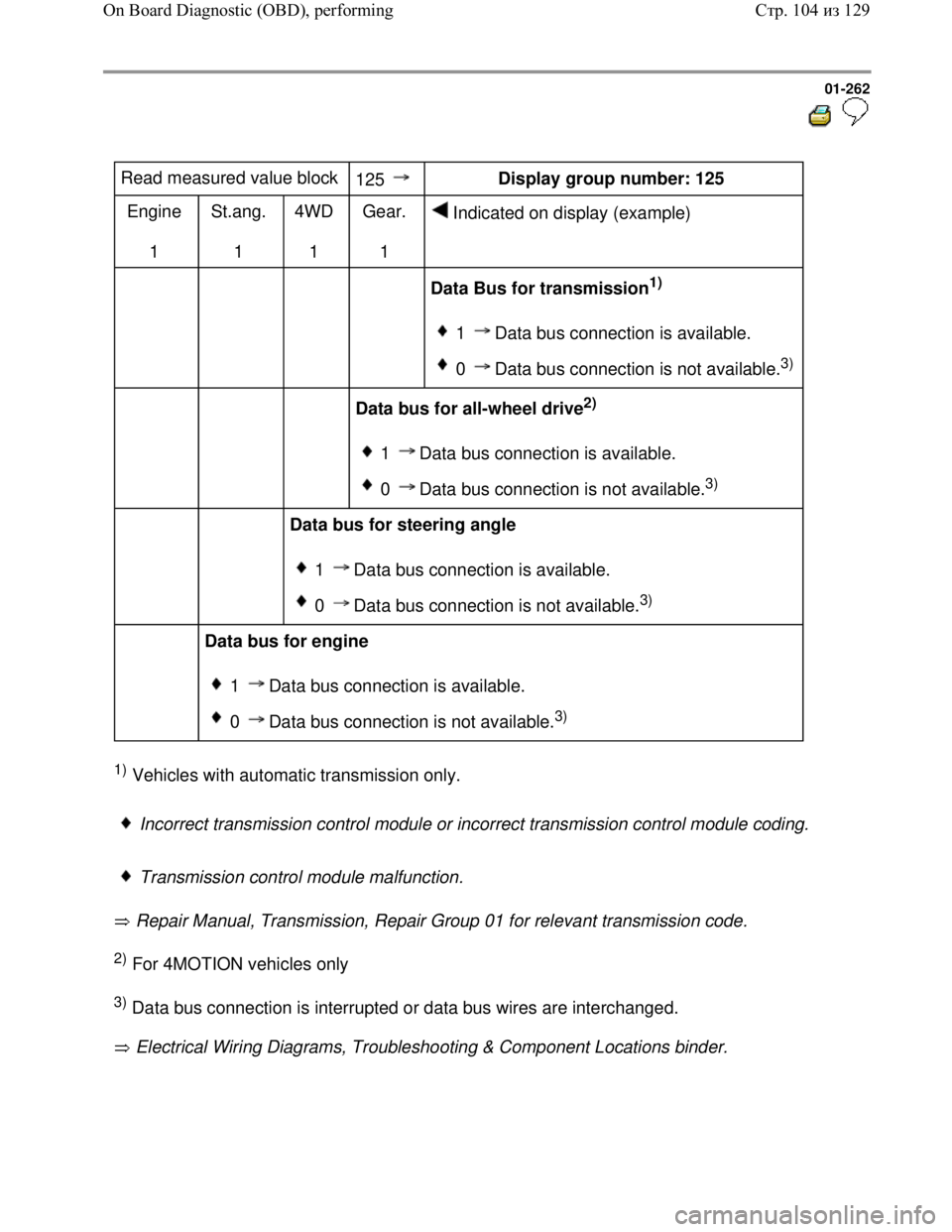
Read measured value block
125 Display group number: 125
Engine
1 St.ang.
1 4WD
1 Gear.
1 Indicated on display (example)
Data Bus for transmission1)
1 Data bus connection is available.
0 Data bus connection is not available.3)
Data bus for all-wheel drive2)
1 Data bus connection is available.
0 Data bus connection is not available.3)
Data bus for steering angle
1 Data bus connection is available.
0 Data bus connection is not available.3)
Data bus for engine
1 Data bus connection is available.
0 Data bus connection is not available.3)
1) Vehicles with automatic transmission only.
Incorrect transmission control module or incorrect transmission control module coding.
Transmission control module malfunction.
Repair Manual, Transmission, Repair Group 01 for relevant transmission code.
2) For 4MOTION vehicles only
3) Data bus connection is interrupted or data bus wires are interchanged.
Electrical Wiring Diagrams, Troubleshooting & Component Locations binder.
Стр. 104из 129 On Board Diagnostic (OBD), performing
Page 272 of 339
Downloaded from www.Manualslib.com manuals search engine 01-264
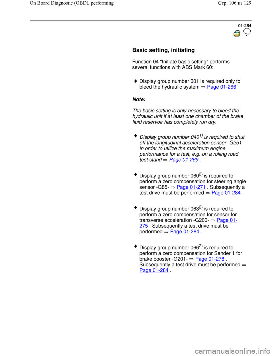
Basic setting, initiating
Function 04 "Initiate basic setting" performs
several functions with ABS Mark 60:
Display group number 001 is required only to
bleed the hydraulic system Page 01
-266
Note:
The basic setting is only necessary to bleed the
hydraulic unit if at least one chamber of the brake
fluid reservoir has completely run dry.
Display group number 0401) is required to shut
off the longitudinal acceleration sensor -G251-
in order to utilize the maximum engine
performance for a test, e.g. on a rolling road
test stand Page 01
-269 .
Display group number 0602) is required to
perform a zero compensation for steering angle
sensor -G85- Page 01
-271 . Subsequently a
test drive must be performed Page 01
-284 .
Display group number 0632) is required to
perform a zero compensation for sensor for
transverse acceleration -G200- Page 01
-
275 . Subsequently a test drive must be
performed Page 01
-284 .
Display group number 0662) is required to
perform a zero compensation for Sender 1 for
brake booster -G201- Page 01
-278 .
Subsequently a test drive must be performed
Page 01
-284 .
Стр. 106из 129 On Board Diagnostic (OBD), performing
Page 273 of 339
Downloaded from www.Manualslib.com manuals search engine 01-265
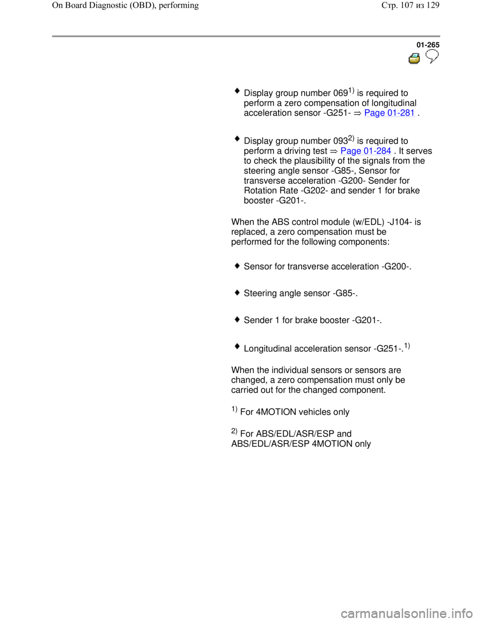
Display group number 0691) is required to
perform a zero compensation of longitudinal
acceleration sensor -G251- Page 01
-281 .
Display group number 0932) is required to
perform a driving test Page 01
-284. It serves
to check the plausibility of the signals from the
steering angle sensor -G85-, Sensor for
transverse acceleration -G200- Sender for
Rotation Rate -G202- and sender 1 for brake
booster -G201-.
When the ABS control module (w/EDL) -J104- is
replaced, a zero compensation must be
performed for the following components:
Sensor for transverse acceleration -G200-.
Steering angle sensor -G85-.
Sender 1 for brake booster -G201-.
Longitudinal acceleration sensor -G251-.1)
When the individual sensors or sensors are
changed, a zero compensation must only be
carried out for the changed component.
1) For 4MOTION vehicles only
2) For ABS/EDL/ASR/ESP and
ABS/EDL/ASR/ESP 4MOTION only
Стр. 107из 129 On Board Diagnostic (OBD), performing
Page 279 of 339
Downloaded from www.Manualslib.com manuals search engine 01-271
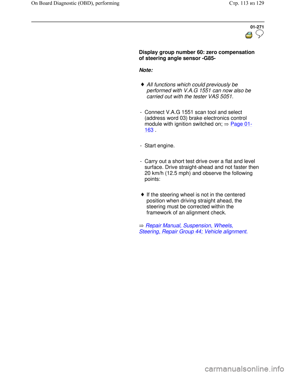
Display group number 60: zero compensation
of steering angle sensor -G85-
Note:
All functions which could previously be
performed with V.A.G 1551 can now also be
carried out with the tester VAS 5051.
- Connect V.A.G 1551 scan tool and select
(address word 03) brake electronics control
module with ignition switched on; Page 01
-
163 .
- Start engine.
- Carry out a short test drive over a flat and level
surface. Drive straight-ahead and not faster then
20 km/h (12.5 mph) and observe the following
points:
If the steering wheel is not in the centered
position when driving straight ahead, the
steering must be corrected within the
framework of an alignment check.
Repair Manual, Suspension, Wheels,
Steering, Repair Group 44; Vehicle alignment.
Стр. 113из 129 On Board Diagnostic (OBD), performing
Page 280 of 339
Downloaded from www.Manualslib.com manuals search engine 01-272
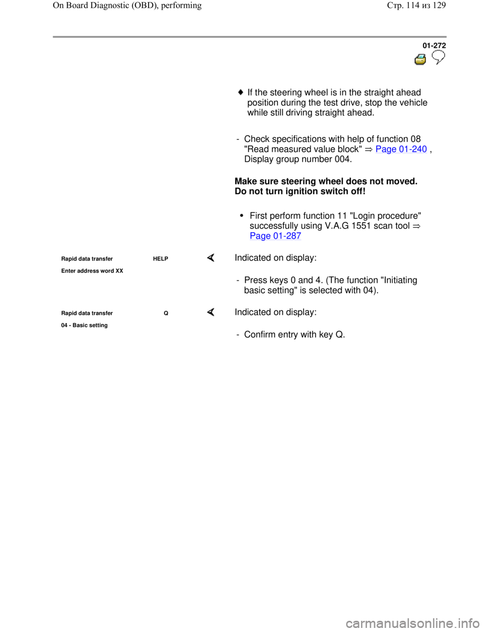
If the steering wheel is in the straight ahead
position during the test drive, stop the vehicle
while still driving straight ahead.
- Check specifications with help of function 08
"Read measured value block" Page 01
-240 ,
Display group number 004.
Make sure steering wheel does not moved.
Do not turn ignition switch off!
First perform function 11 "Login procedure"
successfully using V.A.G 1551 scan tool
Page 01
-287
Rapid data transfer HELP
Enter address word XX Indicated on display:
- Press keys 0 and 4. (The function "Initiating
basic setting" is selected with 04).
Rapid data transfer Q
04 - Basic settin
g
Indicated on display:
- Confirm entry with key Q.
Стр. 114из 129 On Board Diagnostic (OBD), performing
Page 294 of 339
Downloaded from www.Manualslib.com manuals search engine 01-286
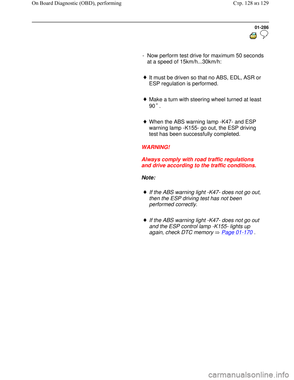
- Now perform test drive for maximum 50 seconds
at a speed of 15km/h...30km/h:
It must be driven so that no ABS, EDL, ASR or
ESP regulation is performed.
Make a turn with steering wheel turned at least
90 .
When the ABS warning lamp -K47- and ESP
warning lamp -K155- go out, the ESP driving
test has been successfully completed.
WARNING!
Always comply with road traffic regulations
and drive according to the traffic conditions.
Note:
If the ABS warning light -K47- does not go out,
then the ESP driving test has not been
performed correctly.
If the ABS warning light -K47- does not go out
and the ESP control lamp -K155- lights up
again, check DTC memory Page 01
-170 .
Стр. 128из 129 On Board Diagnostic (OBD), performing
Page 306 of 339
Downloaded from www.Manualslib.com manuals search engine 01-298
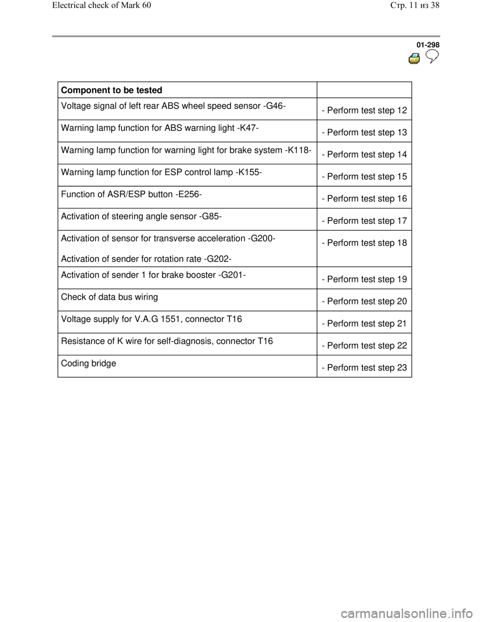
Component to be tested
Voltage signal of left rear ABS wheel speed sensor -G46-
- Perform test step 12
Warning lamp function for ABS warning light -K47-
- Perform test step 13
Warning lamp function for warning light for brake system -K118-
- Perform test step 14
Warning lamp function for ESP control lamp -K155-
- Perform test step 15
Function of ASR/ESP button -E256-
- Perform test step 16
Activation of steering angle sensor -G85-
- Perform test step 17
Activation of sensor for transverse acceleration -G200-
Activation of sender for rotation rate -G202- - Perform test step 18
Activation of sender 1 for brake booster -G201-
- Perform test step 19
Check of data bus wiring
- Perform test step 20
Voltage supply for V.A.G 1551, connector T16
- Perform test step 21
Resistance of K wire for self-diagnosis, connector T16
- Perform test step 22
Coding bridge
- Perform test step 23
Стр. 11из 38 Electrical check of Mark 60
Page 321 of 339
Downloaded from www.Manualslib.com manuals search engine 01-313
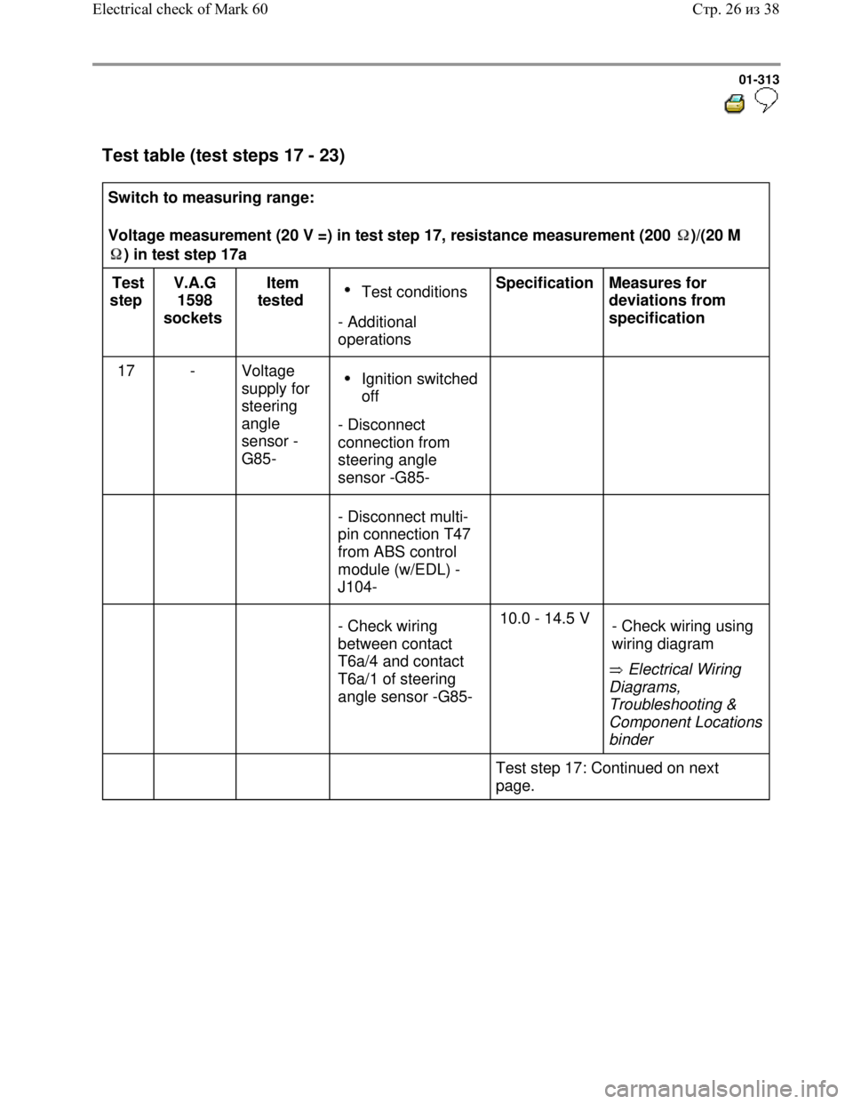
Test table (test steps 17 - 23)
Switch to measuring range:
Voltage measurement (20 V =) in test step 17, resistance measurement (200 )/(20 M
) in test step 17a
Test
step V.A.G
1598
sockets Item
tested Test conditions
- Additional
operations Specification
Measures for
deviations from
specification
17 - Voltage
supply for
steering
angle
sensor -
G85-
Ignition switched
off
- Disconnect
connection from
steering angle
sensor -G85-
- Disconnect multi-
pin connection T47
from ABS control
module (w/EDL) -
J104-
- Check wiring
between contact
T6a/4 and contact
T6a/1 of steering
angle sensor -G85- 10.0 - 14.5 V
Electrical Wiring
Diagrams,
Troubleshooting &
Component Locations
binder - Check wiring using
wiring diagram
Test step 17: Continued on next
page.
Стр. 26из 38 Electrical check of Mark 60