display VOLKSWAGEN JETTA 1998 Repair Manual
[x] Cancel search | Manufacturer: VOLKSWAGEN, Model Year: 1998, Model line: JETTA, Model: VOLKSWAGEN JETTA 1998Pages: 339, PDF Size: 2.35 MB
Page 97 of 339

Downloaded from www.Manualslib.com manuals search engine 01-94
System in basic setting 3
De
press pedal and hold...
Indicated on display
- Operate pedal with substantial foot
pressure and hold.
Pedal moves down
Hydraulic pump runs
Pedal comes back
System in basic setting 3
Rel. pedal; FR/FL bleed screw OPEN <3> Indicated on display
- Press key 3 on V.A.G 1551 or arrow up
key on VAS 5051.
System in basic setting 4
Please wait...
(10 secs.)
Indicated on display
Hydraulic pump runs
System in basic setting 4
Depr. pedal 10X; bleed screw CLOSED <3> Indicated on display
- Press key 3 on V.A.G 1551 or arrow up
key on VAS 5051.
Стр. 74из 81 ABS ITT Mk 20 IE On Board Diagnostic (OBD) program
Page 98 of 339
Downloaded from www.Manualslib.com manuals search engine 01-95
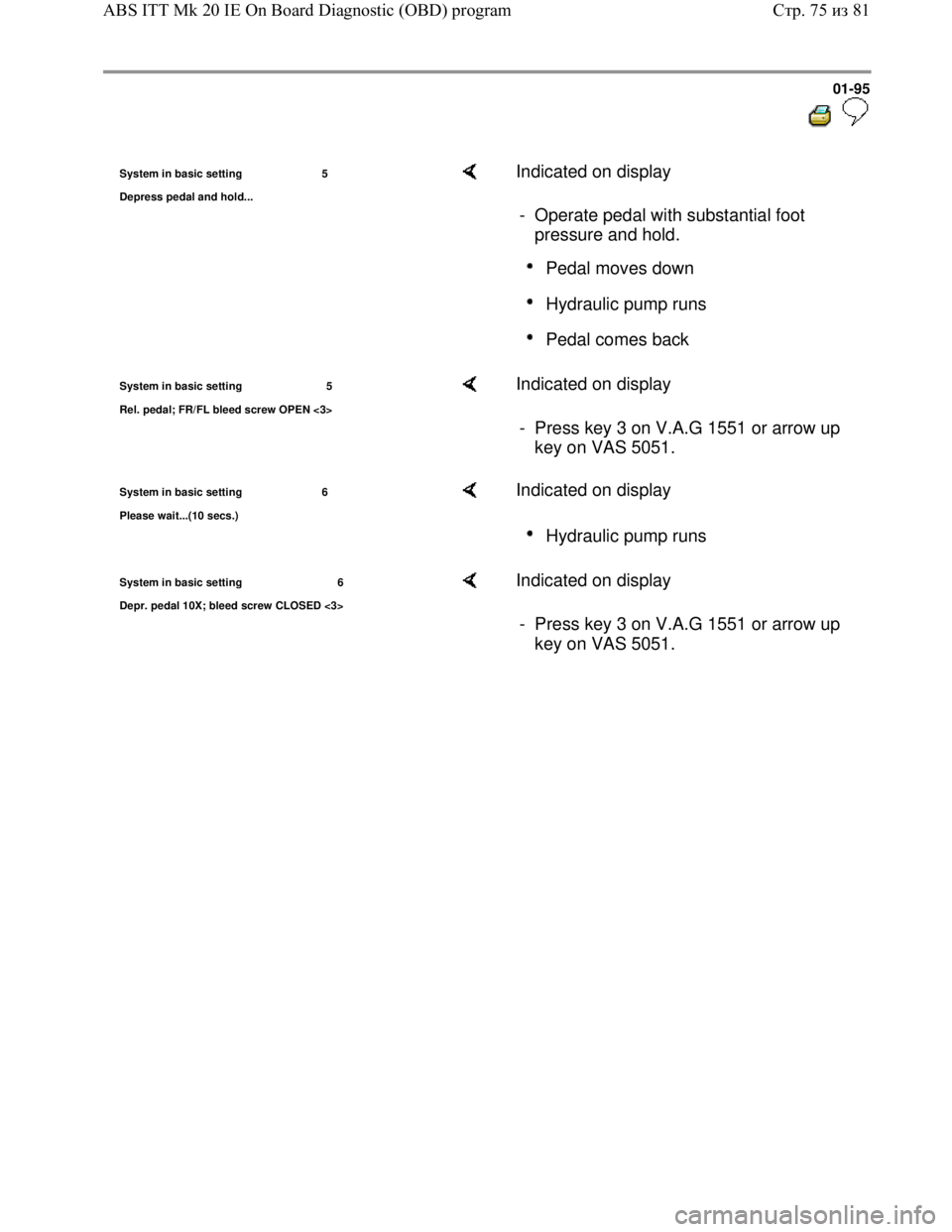
System in basic setting 5
De
press pedal and hold...
Indicated on display
- Operate pedal with substantial foot
pressure and hold.
Pedal moves down
Hydraulic pump runs
Pedal comes back
System in basic setting 5
Rel. pedal; FR/FL bleed screw OPEN <3> Indicated on display
- Press key 3 on V.A.G 1551 or arrow up
key on VAS 5051.
System in basic setting 6
Please wait...
(10 secs.)
Indicated on display
Hydraulic pump runs
System in basic setting 6
Depr. pedal 10X; bleed screw CLOSED <3> Indicated on display
- Press key 3 on V.A.G 1551 or arrow up
key on VAS 5051.
Стр. 75из 81 ABS ITT Mk 20 IE On Board Diagnostic (OBD) program
Page 99 of 339
Downloaded from www.Manualslib.com manuals search engine 01-96
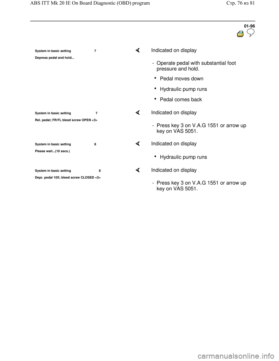
System in basic setting 7
De
press pedal and hold...
Indicated on display
- Operate pedal with substantial foot
pressure and hold.
Pedal moves down
Hydraulic pump runs
Pedal comes back
System in basic setting 7
Rel. pedal; FR/FL bleed screw OPEN <3> Indicated on display
- Press key 3 on V.A.G 1551 or arrow up
key on VAS 5051.
System in basic setting 8
Please wait...
(10 secs.)
Indicated on display
Hydraulic pump runs
System in basic setting 8
Depr. pedal 10X; bleed screw CLOSED <3> Indicated on display
- Press key 3 on V.A.G 1551 or arrow up
key on VAS 5051.
Стр. 76из 81 ABS ITT Mk 20 IE On Board Diagnostic (OBD) program
Page 100 of 339
Downloaded from www.Manualslib.com manuals search engine 01-97
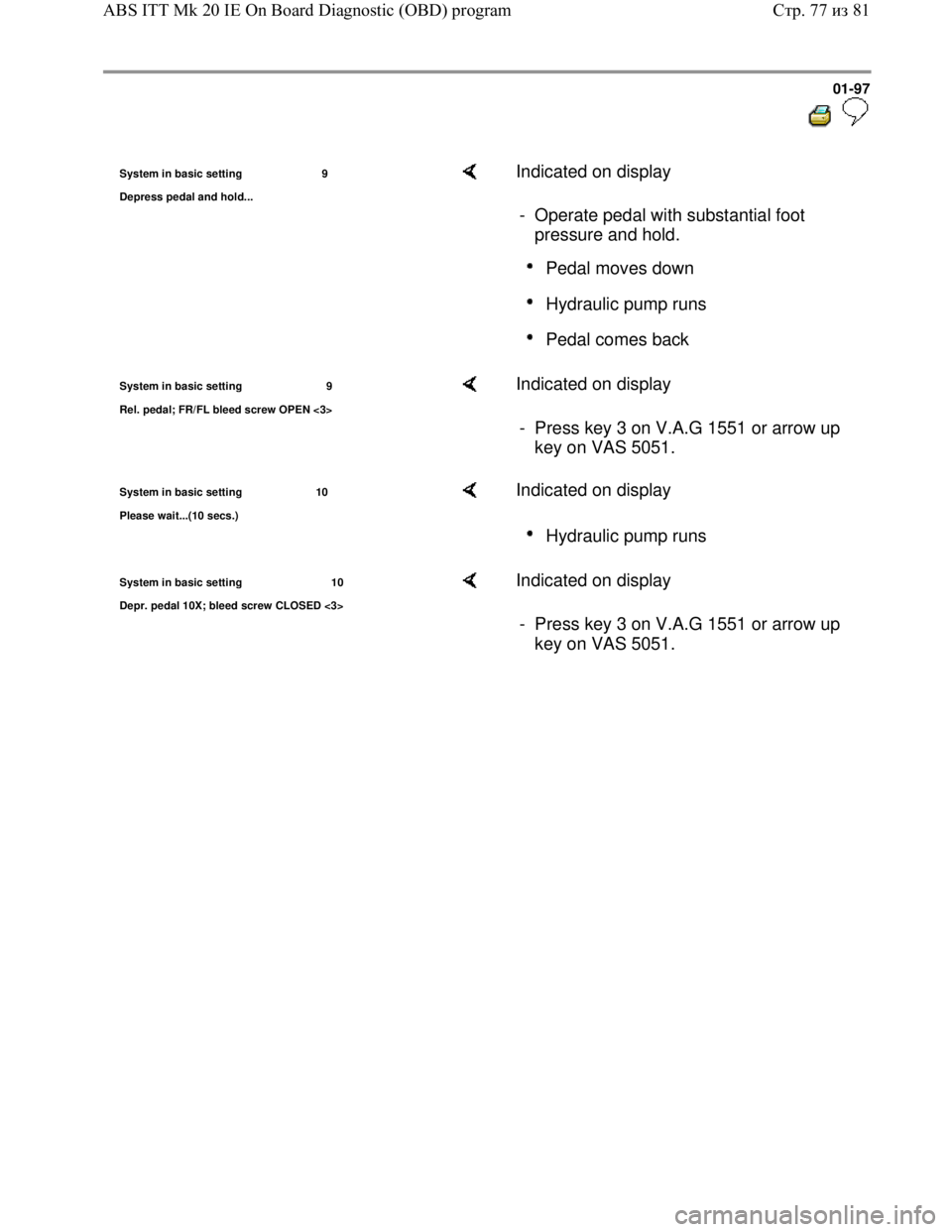
System in basic setting 9
De
press pedal and hold...
Indicated on display
- Operate pedal with substantial foot
pressure and hold.
Pedal moves down
Hydraulic pump runs
Pedal comes back
System in basic setting 9
Rel. pedal; FR/FL bleed screw OPEN <3> Indicated on display
- Press key 3 on V.A.G 1551 or arrow up
key on VAS 5051.
System in basic setting 10
Please wait...
(10 secs.)
Indicated on display
Hydraulic pump runs
System in basic setting 10
Depr. pedal 10X; bleed screw CLOSED <3> Indicated on display
- Press key 3 on V.A.G 1551 or arrow up
key on VAS 5051.
Стр. 77из 81 ABS ITT Mk 20 IE On Board Diagnostic (OBD) program
Page 101 of 339
Downloaded from www.Manualslib.com manuals search engine 01-98
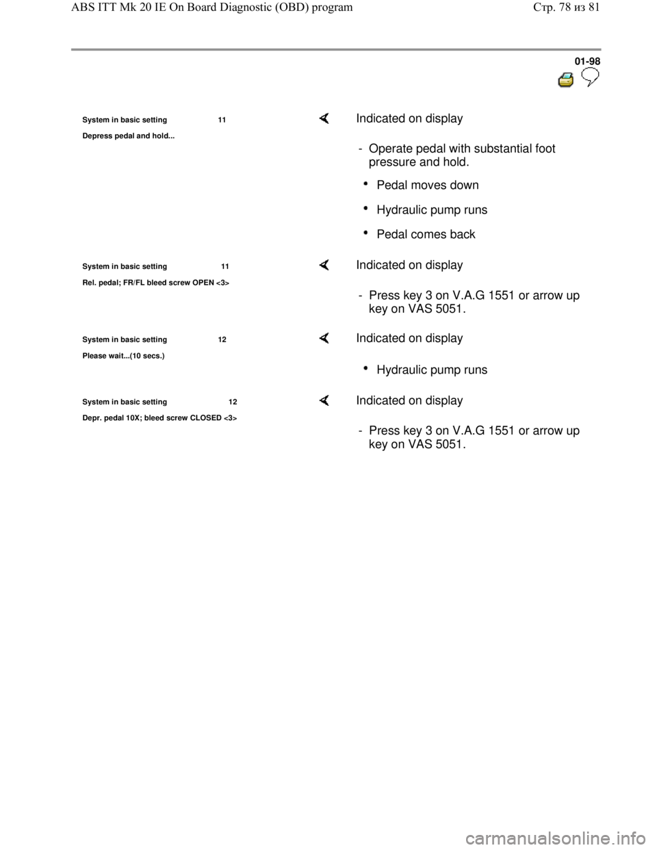
System in basic setting 11
De
press pedal and hold...
Indicated on display
- Operate pedal with substantial foot
pressure and hold.
Pedal moves down
Hydraulic pump runs
Pedal comes back
System in basic setting 11
Rel. pedal; FR/FL bleed screw OPEN <3> Indicated on display
- Press key 3 on V.A.G 1551 or arrow up
key on VAS 5051.
System in basic setting 12
Please wait...
(10 secs.)
Indicated on display
Hydraulic pump runs
System in basic setting 12
Depr. pedal 10X; bleed screw CLOSED <3> Indicated on display
- Press key 3 on V.A.G 1551 or arrow up
key on VAS 5051.
Стр. 78из 81 ABS ITT Mk 20 IE On Board Diagnostic (OBD) program
Page 102 of 339
Downloaded from www.Manualslib.com manuals search engine 01-99
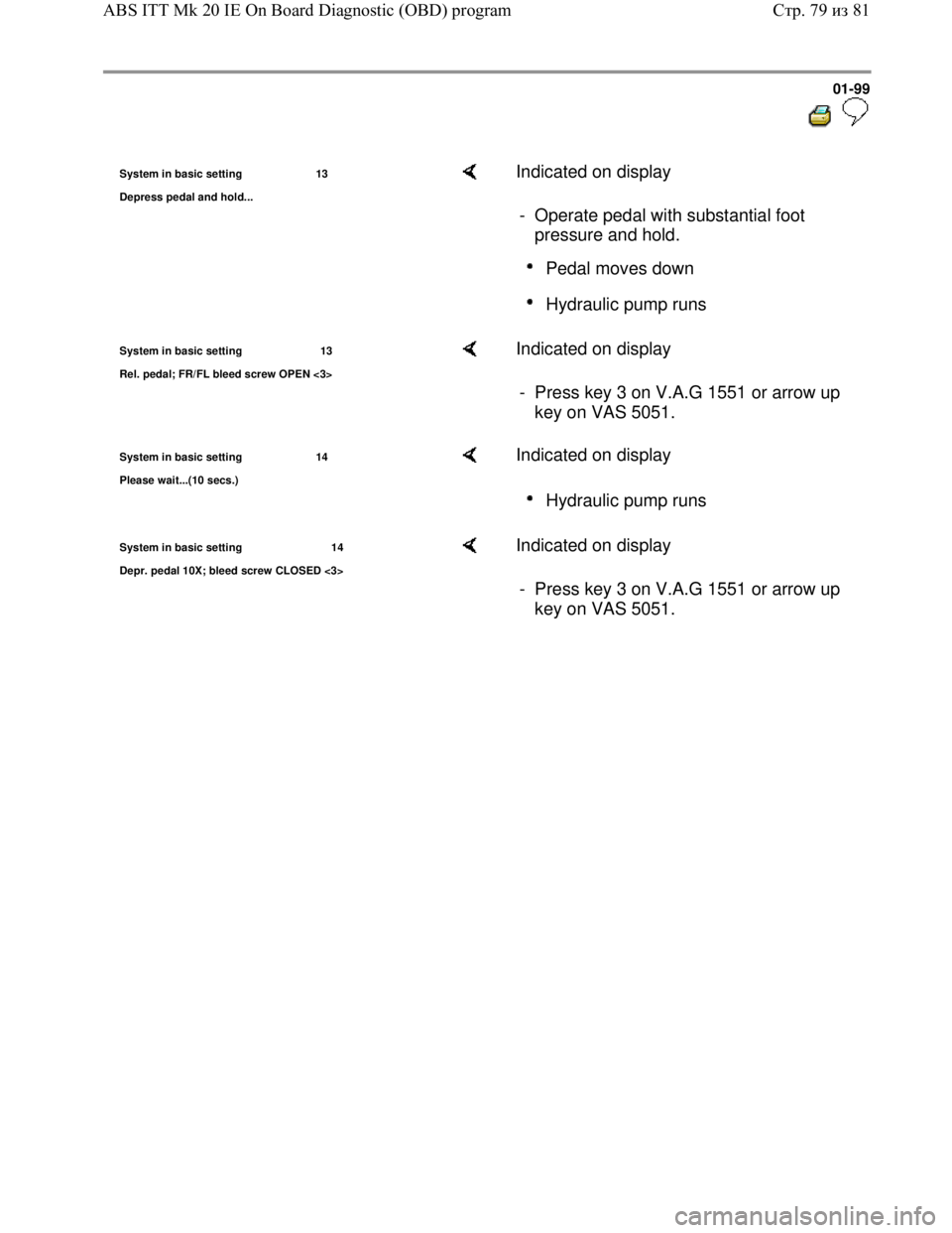
System in basic setting 13
De
press pedal and hold...
Indicated on display
- Operate pedal with substantial foot
pressure and hold.
Pedal moves down
Hydraulic pump runs
System in basic setting 13
Rel. pedal; FR/FL bleed screw OPEN <3> Indicated on display
- Press key 3 on V.A.G 1551 or arrow up
key on VAS 5051.
System in basic setting 14
Please wait...
(10 secs.)
Indicated on display
Hydraulic pump runs
System in basic setting 14
Depr. pedal 10X; bleed screw CLOSED <3> Indicated on display
- Press key 3 on V.A.G 1551 or arrow up
key on VAS 5051.
Стр. 79из 81 ABS ITT Mk 20 IE On Board Diagnostic (OBD) program
Page 103 of 339
Downloaded from www.Manualslib.com manuals search engine 01-100
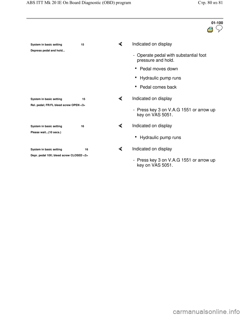
System in basic setting 15
De
press pedal and hold...
Indicated on display
- Operate pedal with substantial foot
pressure and hold.
Pedal moves down
Hydraulic pump runs
Pedal comes back
System in basic setting 15
Rel. pedal; FR/FL bleed screw OPEN <3> Indicated on display
- Press key 3 on V.A.G 1551 or arrow up
key on VAS 5051.
System in basic setting 16
Please wait...
(10 secs.)
Indicated on display
Hydraulic pump runs
System in basic setting 16
Depr. pedal 10X; bleed screw CLOSED <3> Indicated on display
- Press key 3 on V.A.G 1551 or arrow up
key on VAS 5051.
Стр. 80из 81 ABS ITT Mk 20 IE On Board Diagnostic (OBD) program
Page 104 of 339
Downloaded from www.Manualslib.com manuals search engine 01-101
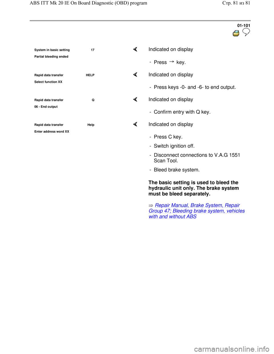
System in basic setting 17
Partial bleedin
g ended
Indicated on display
-
Press key.
Rapid data transfer HELP
Select function XX Indicated on display
- Press keys -0- and -6- to end output.
Rapid data transfer Q
06 - End output Indicated on display
- Confirm entry with Q key.
Rapid data transfer Help
Enter address word XX Indicated on display
The basic setting is used to bleed the
hydraulic unit only. The brake system
must be bleed separately.
Repair Manual, Brake System, Repair
Group 47; Bleeding brake system, vehicles
with and without ABS - Press C key.
- Switch ignition off.
- Disconnect connections to V.A.G 1551
Scan Tool.
- Bleed brake system.
Стр. 81из 81 ABS ITT Mk 20 IE On Board Diagnostic (OBD) program
Page 116 of 339
Downloaded from www.Manualslib.com manuals search engine 01-113
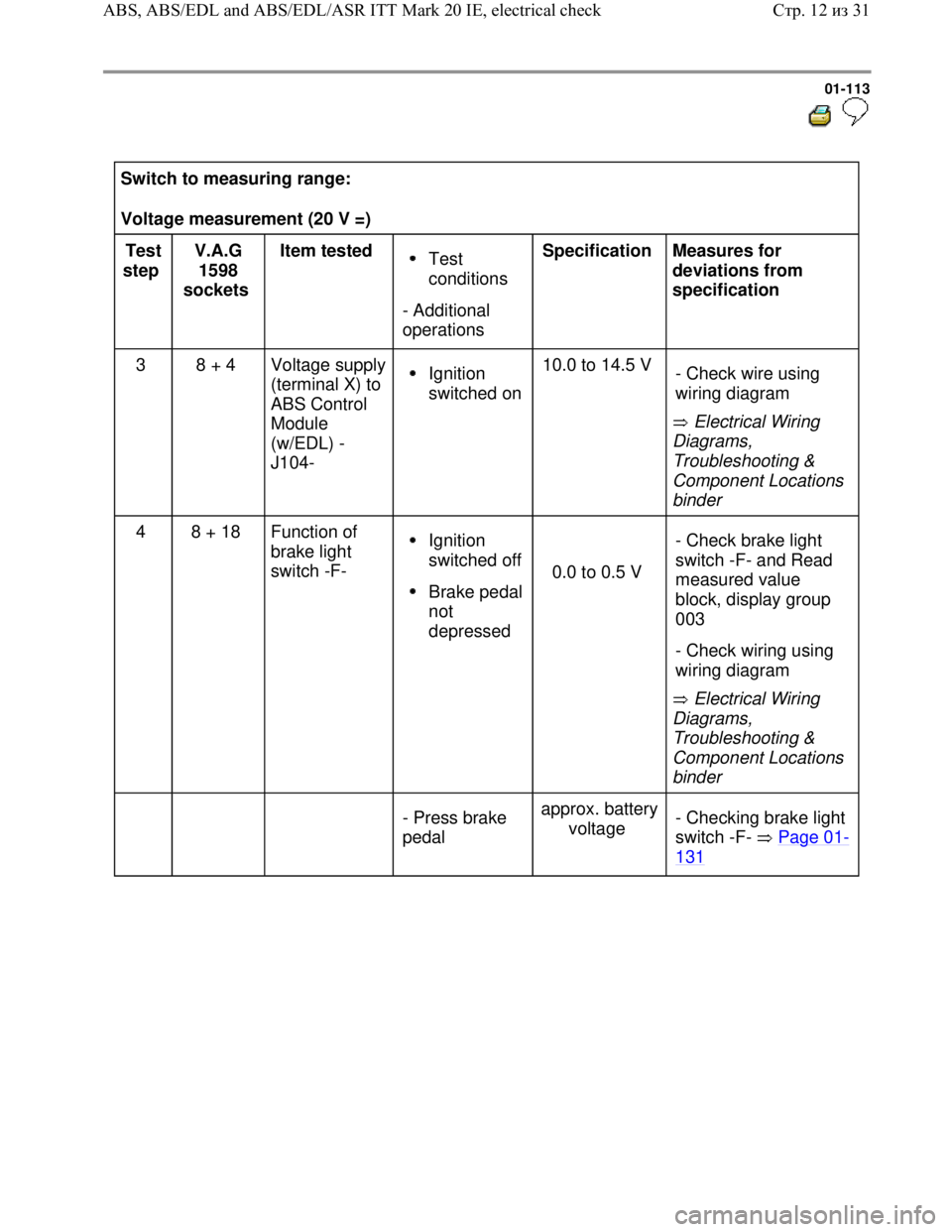
Switch to measuring range:
Voltage measurement (20 V =)
Test
step V.A.G
1598
sockets Item tested
Test
conditions
- Additional
operations Specification
Measures for
deviations from
specification
3 8 + 4 Voltage supply
(terminal X) to
ABS Control
Module
(w/EDL) -
J104-
Ignition
switched on10.0 to 14.5 V
Electrical Wiring
Diagrams,
Troubleshooting &
Component Locations
binder - Check wire using
wiring diagram
4 8 + 18 Function of
brake light
switch -F- Ignition
switched off
Brake pedal
not
depressed
0.0 to 0.5 V
Electrical Wiring
Diagrams,
Troubleshooting &
Component Locations
binder - Check brake light
switch -F- and Read
measured value
block, display group
003
- Check wiring using
wiring diagram
- Press brake
pedal approx. battery
voltage - Checking brake light
switch -F- Page 01
-
131
Стр. 12из 31 ABS, ABS/EDL and ABS/EDL/ASR ITT Mark 20 IE, electrical check
Page 121 of 339

Downloaded from www.Manualslib.com manuals search engine 01-118
Switch to measuring range:
Voltage measurement (2 V )
Test
step V.A.G
1598
sockets Item
tested Test
conditions
- Additional
operations Specification
Measures for deviations
from specification
9 19 + 20 Right front
ABS wheel
speed
sensor -
G45-
voltage
signal
Vehicle
raised
- Check installation of
right front ABS wheel
speed sensor -G45- and
rotor.
Ignition
switched off
- Rotate front
right wheel at
approx. 1
rev./sec. min. 65 mV
alternating
voltage - Check whether right
front ABS wheel speed
sensor -G45- has been
interchanged and Read
measured value block
Page 01
-61 , display
group number 001
10 1 + 2 Left front
ABS wheel
speed
sensor -
G47-
voltage
signal Vehicle
raised
- Check installation of left
front ABS wheel speed
sensor -G47- and rotor.
Ignition
switched off
- Rotate front
left wheel at
approx. 1
rev./sec. min. 65 mV
alternating
voltage - Check whether left front
ABS wheel speed sensor
-G47- has been
interchanged and Read
measured value block
Page 01
-61 , display
group number 001
Стр. 17из 31 ABS, ABS/EDL and ABS/EDL/ASR ITT Mark 20 IE, electrical check