display VOLKSWAGEN PASSAT 1995 B3, B4 / 3.G Service Workshop Manual
[x] Cancel search | Manufacturer: VOLKSWAGEN, Model Year: 1995, Model line: PASSAT, Model: VOLKSWAGEN PASSAT 1995 B3, B4 / 3.GPages: 369, PDF Size: 12.33 MB
Page 319 of 369
Downloaded from www.Manualslib.com manuals search engine 48-49
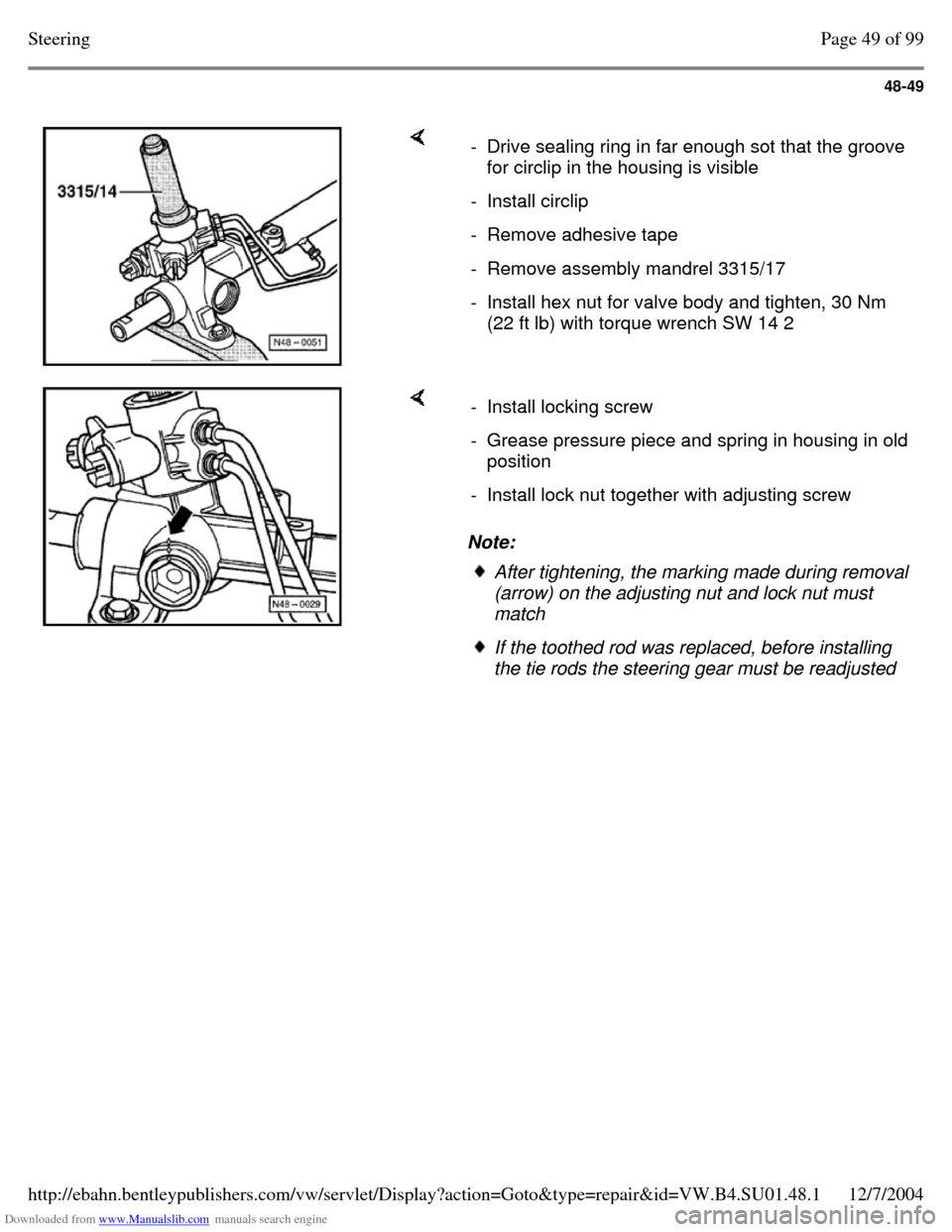
- Drive sealing ring in far enough sot that the groove for circlip in the housing is visible
- Install circlip - Remove adhesive tape - Remove assembly mandrel 3315/17 - Install hex nut for valve body and tighten, 30 Nm
(22 ft lb) with torque wrench SW 14 2 Note: - Install locking screw - Grease pressure piece and spring in housing in old position
- Install lock nut together with adjusting screw After tightening, the marking made during removal (arrow) on the adjusting nut and lock nut must
match If the toothed rod was replaced, before installing
the tie rods the steering gear must be readjusted Page 49 of 99Steering12/7/2004http://ebahn.bentleypublishers.com/vw/servlet/Display?action=Goto&type=repair&id=VW.B4.SU01.48.1
Page 320 of 369
Downloaded from www.Manualslib.com manuals search engine 48-50
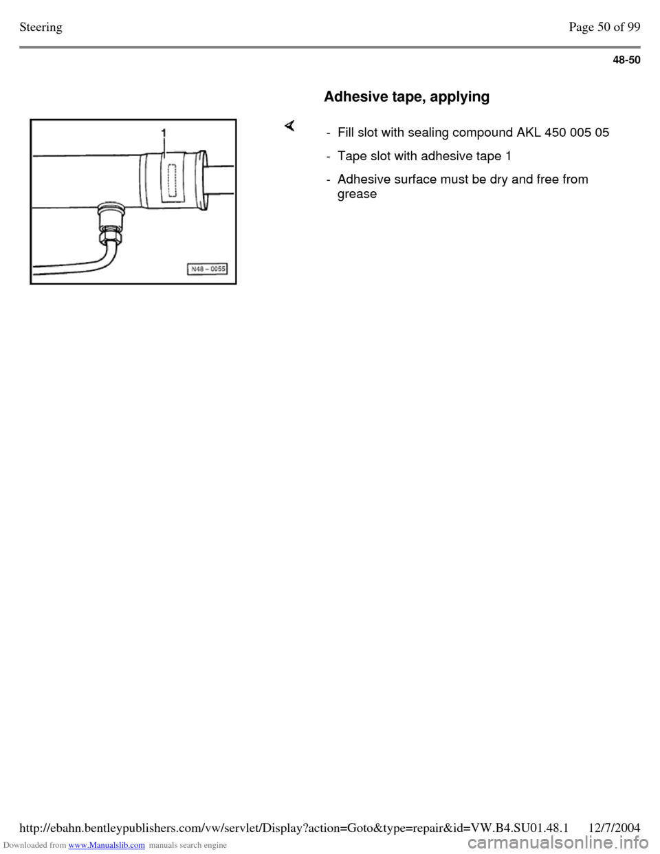
Adhesive tape, applying - Fill slot with sealing compound AKL 450 005 05 - Tape slot with adhesive tape 1 - Adhesive surface must be dry and free from
grease Page 50 of 99Steering12/7/2004http://ebahn.bentleypublishers.com/vw/servlet/Display?action=Goto&type=repair&id=VW.B4.SU01.48.1
Page 321 of 369
Downloaded from www.Manualslib.com manuals search engine 48-51
Power steering gear, adjusting with new
toothed rod If a new toothed rod was used, the steering play
should be adjusted according to the following
description.
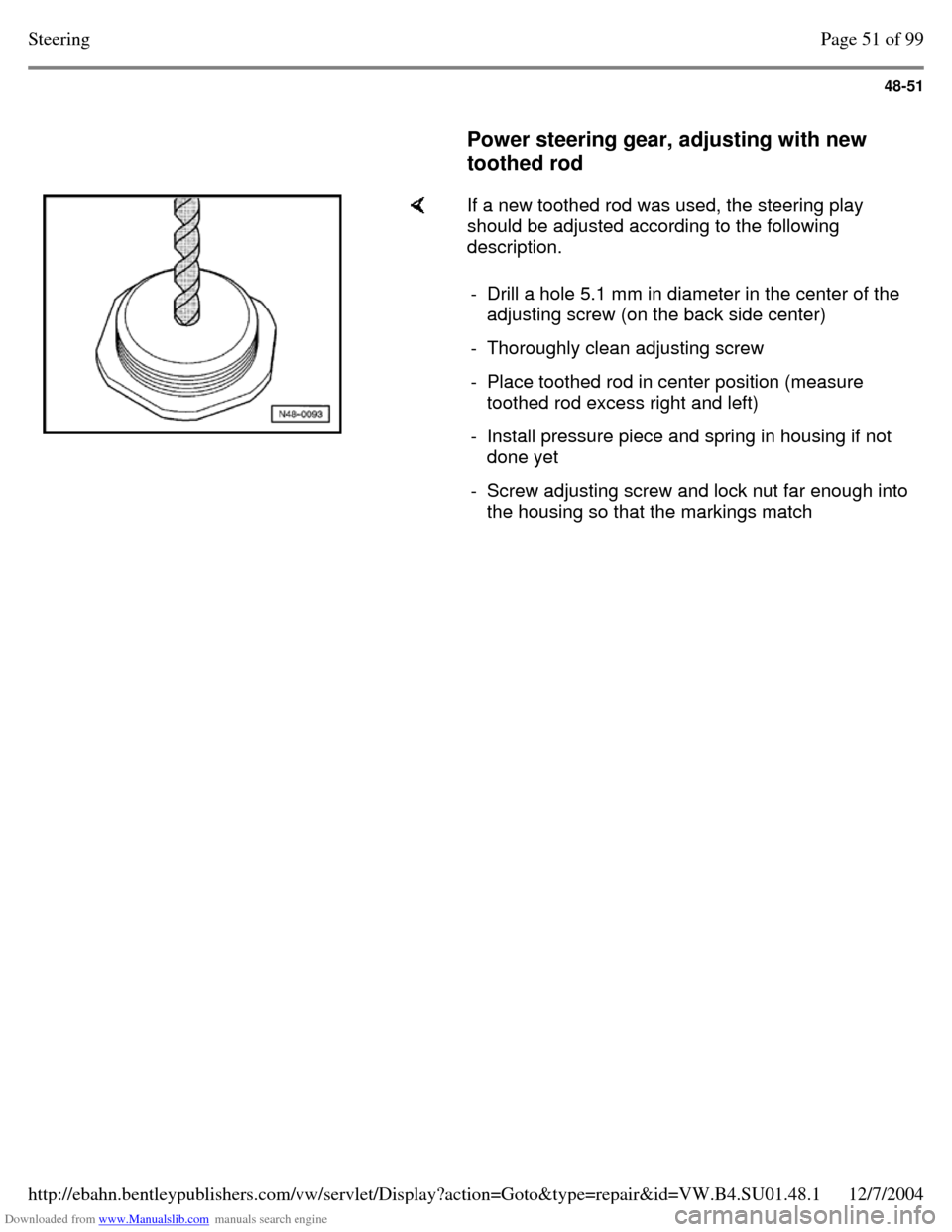
- Drill a hole 5.1 mm in diameter in the center of the
adjusting screw (on the back side center)
- Thoroughly clean adjusting screw - Place toothed rod in center position (measure
toothed rod excess right and left)
- Install pressure piece and spring in housing if not
done yet
- Screw adjusting screw and lock nut far enough into the housing so that the markings match Page 51 of 99Steering12/7/2004http://ebahn.bentleypublishers.com/vw/servlet/Display?action=Goto&type=repair&id=VW.B4.SU01.48.1
Page 322 of 369
Downloaded from www.Manualslib.com manuals search engine 48-52
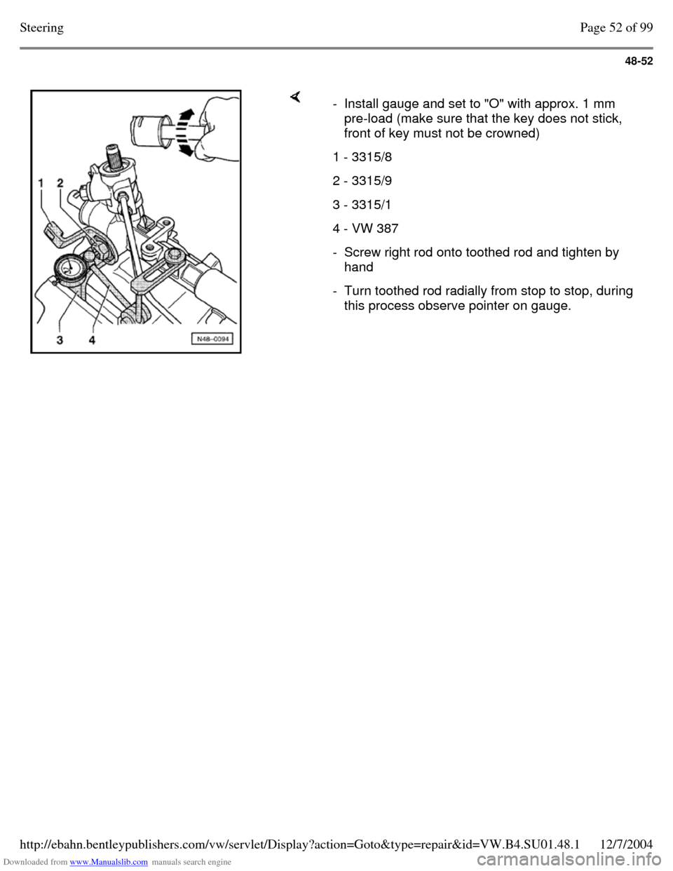
- Install gauge and set to "O" with approx. 1 mm
pre-load (make sure that the key does not stick,
front of key must not be crowned)
1 - 3315/8 2 - 3315/9 3 - 3315/1 4 - VW 387 - Screw right rod onto toothed rod and tighten by
hand
- Turn toothed rod radially from stop to stop, during
this process observe pointer on gauge. Page 52 of 99Steering12/7/2004http://ebahn.bentleypublishers.com/vw/servlet/Display?action=Goto&type=repair&id=VW.B4.SU01.48.1
Page 323 of 369
Downloaded from www.Manualslib.com manuals search engine 48-53
Needle run-out max. 0.10 mm
If needle run-out is greater than 0.10 mm, screw
pressure piece slightly into housing
If the needle run-out is less than 0.10 mm, screw
pressure piece slightly out of housing
- Tighten lock nut
- Check needle run-out again, if necessary repeat
adjustment
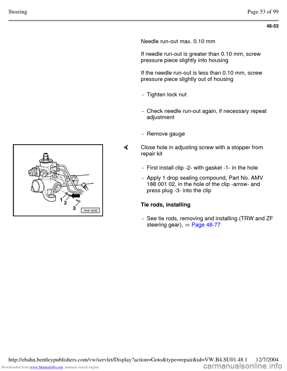
- Remove gauge Close hole in adjusting screw with a stopper from
repair kit
Tie rods, installing - First install clip -2- with gasket -1- in the hole - Apply 1 drop sealing compound, Part No. AMV
188 001 02, in the hole of the clip -arrow- and
press plug -3- into the clip
- See tie rods, removing and installing (TRW and ZF steering gear), Page 48-77 Page 53 of 99Steering12/7/2004http://ebahn.bentleypublishers.com/vw/servlet/Display?action=Goto&type=repair&id=VW.B4.SU01.48.1
Page 324 of 369
Downloaded from www.Manualslib.com manuals search engine 48-54
Assembly overview: power steering
gear (ZF)
It is not intended that repair work be carried out
on the power steering gear. If complaints are
received determine cause with the help of
pressure tests, leakage test and troubleshooting
programs. If a malfunction exists replace the
power steering gear.
Note:
Always replace self-locking nuts and bolts. Welding and straightening work on steering
components is not permitted.
To grease the rack use only steering gear
grease, Part No. AOF 063 000 04.
Type of oil: Hydraulic oil G 002 000 Oil system capacity: 0.7 - 0.9 Itr. (0.74 - 0.95
qt)
Supply and pressure line routing Page 48-85 . Page 54 of 99Steering12/7/2004http://ebahn.bentleypublishers.com/vw/servlet/Display?action=Goto&type=repair&id=VW.B4.SU01.48.1
Page 325 of 369
Downloaded from www.Manualslib.com manuals search engine 48-55
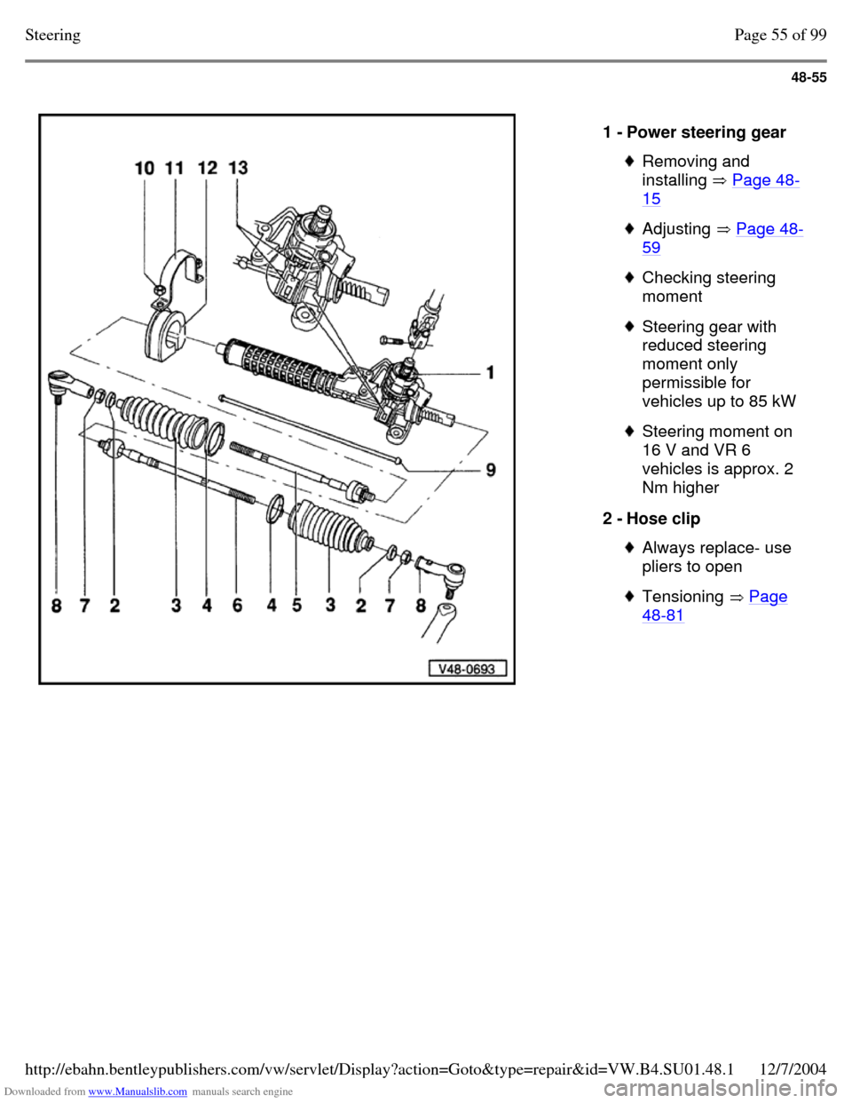
1 - Power steering gear Removing and
installing Page 48-15 Adjusting Page 48-59 Checking steering
moment Steering gear with
reduced steering
moment only
permissible for
vehicles up to 85 kW Steering moment on
16 V and VR 6
vehicles is approx. 2
Nm higher
2 - Hose clip Always replace- use
pliers to open Tensioning Page 48-81 Page 55 of 99Steering12/7/2004http://ebahn.bentleypublishers.com/vw/servlet/Display?action=Goto&type=repair&id=VW.B4.SU01.48.1
Page 326 of 369
Downloaded from www.Manualslib.com manuals search engine 48-56
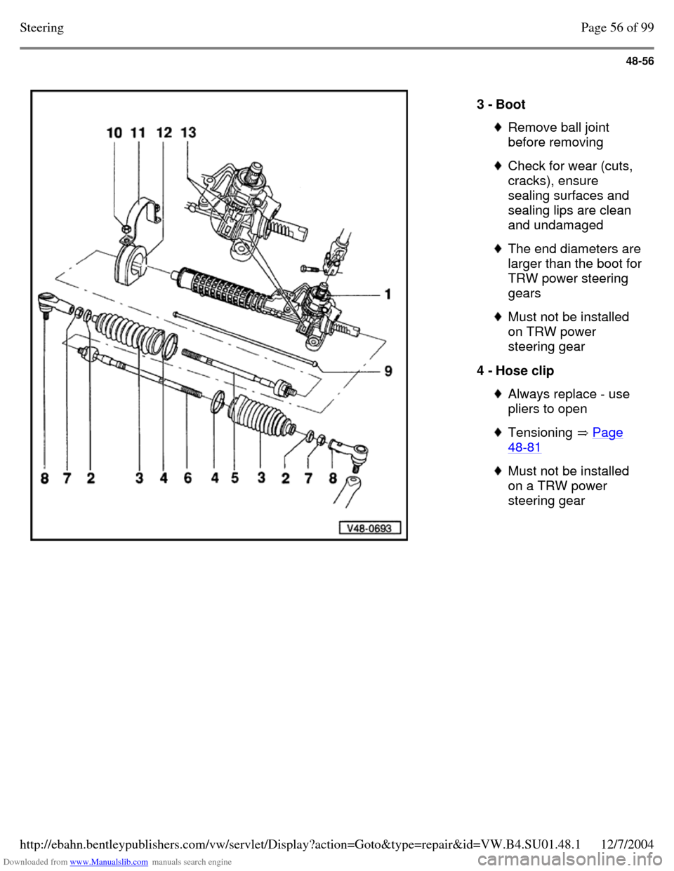
3 - Boot Remove ball joint
before removing Check for wear (cuts,
cracks), ensure
sealing surfaces and
sealing lips are clean
and undamaged The end diameters are larger than the boot for TRW power steering
gears Must not be installed
on TRW power
steering gear
4 - Hose clip Always replace - use
pliers to open Tensioning Page 48-81 Must not be installed
on a TRW power
steering gear Page 56 of 99Steering12/7/2004http://ebahn.bentleypublishers.com/vw/servlet/Display?action=Goto&type=repair&id=VW.B4.SU01.48.1
Page 327 of 369
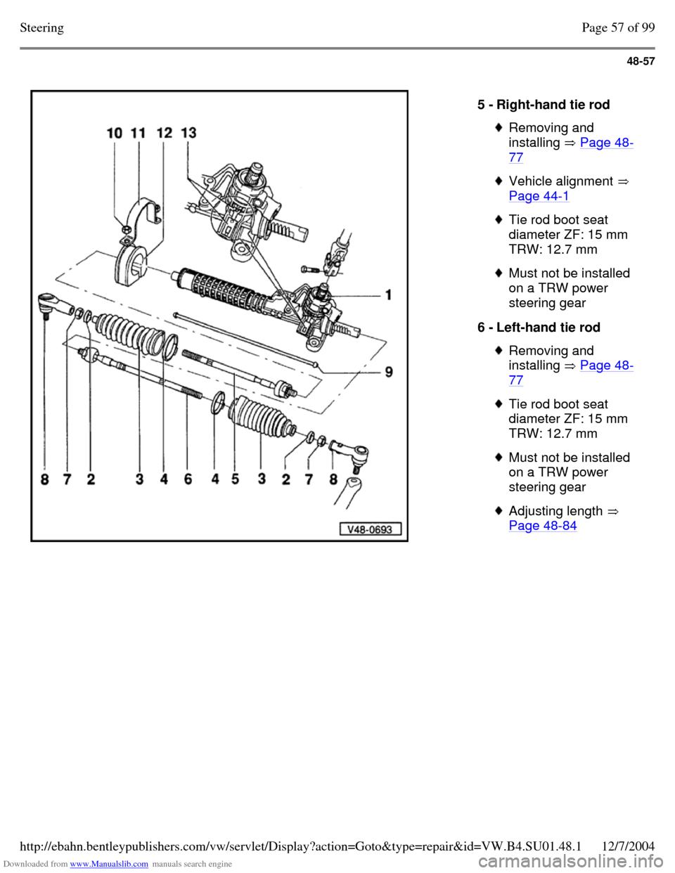
Downloaded from www.Manualslib.com manuals search engine 48-57
5 - Right-hand tie rod Removing and
installing Page 48-77 Vehicle alignment
Page 44-1 Tie rod boot seat
diameter ZF: 15 mm
TRW: 12.7 mm Must not be installed
on a TRW power
steering gear
6 - Left-hand tie rod Removing and
installing Page 48-77 Tie rod boot seat
diameter ZF: 15 mm
TRW: 12.7 mm Must not be installed
on a TRW power
steering gear Adjusting length
Page 48-84 Page 57 of 99Steering12/7/2004http://ebahn.bentleypublishers.com/vw/servlet/Display?action=Goto&type=repair&id=VW.B4.SU01.48.1
Page 328 of 369
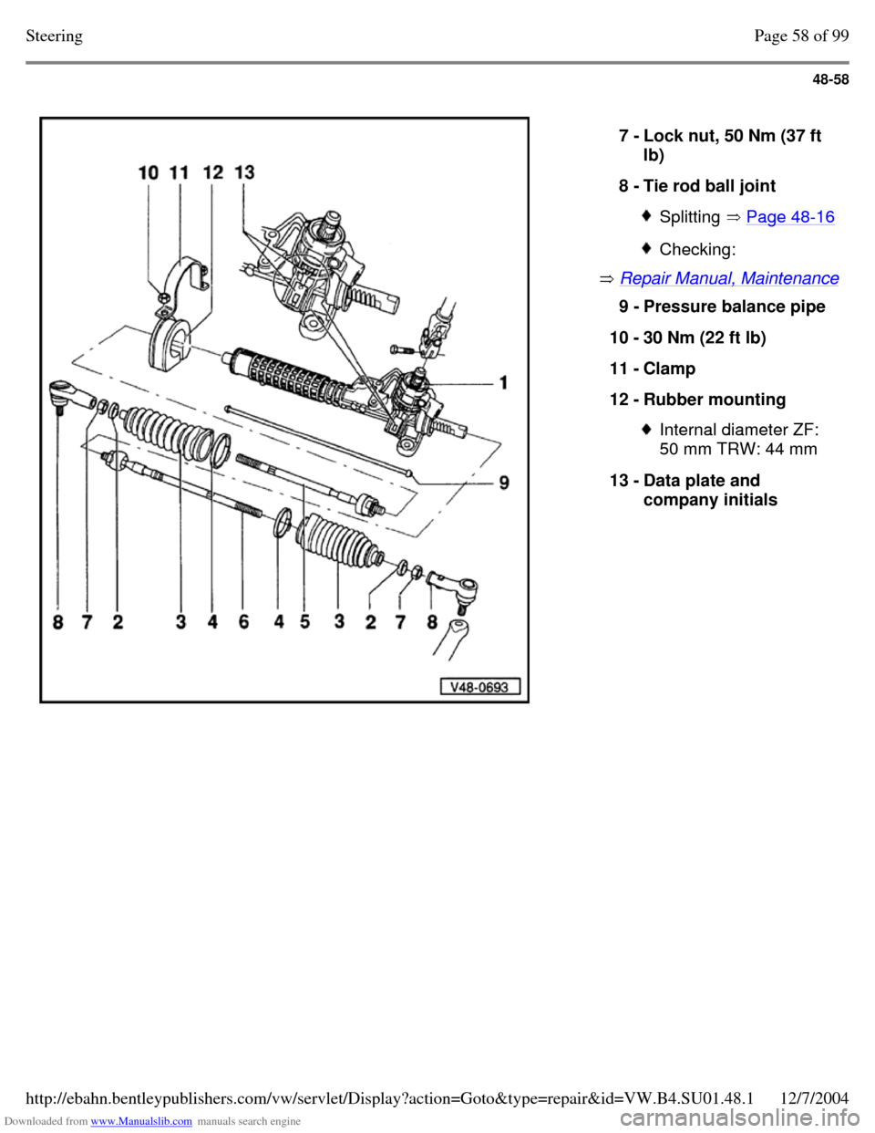
Downloaded from www.Manualslib.com manuals search engine 48-58
Repair Manual, Maintenance 7 - Lock nut, 50 Nm (37 ft
lb)
8 - Tie rod ball joint Splitting Page 48-16 Checking: 9 - Pressure balance pipe
10 - 30 Nm (22 ft lb)
11 - Clamp
12 - Rubber mounting Internal diameter ZF:
50 mm TRW: 44 mm
13 - Data plate and
company initials Page 58 of 99Steering12/7/2004http://ebahn.bentleypublishers.com/vw/servlet/Display?action=Goto&type=repair&id=VW.B4.SU01.48.1