display VOLKSWAGEN PASSAT 1995 B3, B4 / 3.G Service Workshop Manual
[x] Cancel search | Manufacturer: VOLKSWAGEN, Model Year: 1995, Model line: PASSAT, Model: VOLKSWAGEN PASSAT 1995 B3, B4 / 3.GPages: 369, PDF Size: 12.33 MB
Page 299 of 369
Downloaded from www.Manualslib.com manuals search engine 48-29
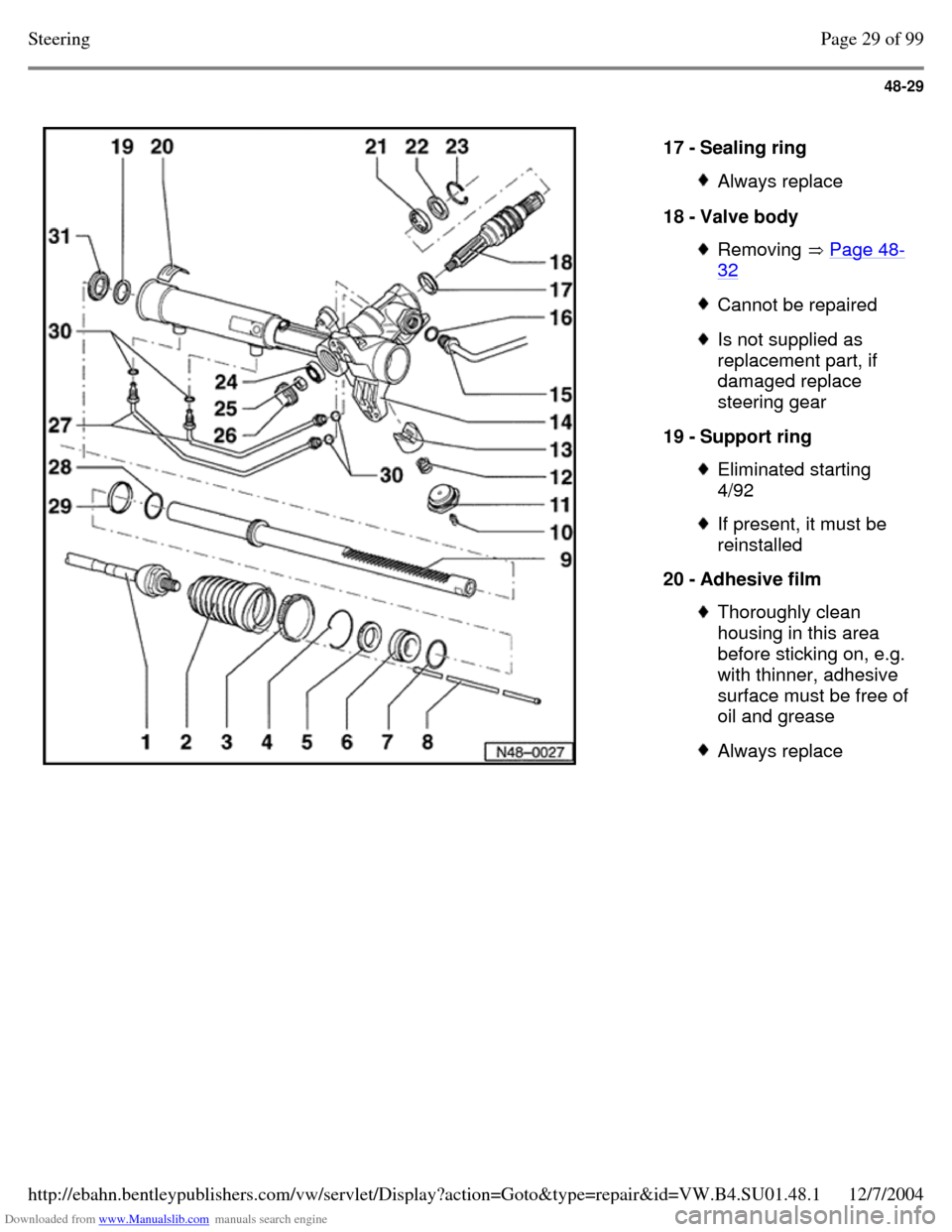
17 - Sealing ring Always replace 18 - Valve body Removing Page 48-32 Cannot be repaired Is not supplied as
replacement part, if
damaged replace
steering gear
19 - Support ring Eliminated starting
4/92 If present, it must be
reinstalled
20 - Adhesive film Thoroughly clean
housing in this area before sticking on, e.g. with thinner, adhesive surface must be free of oil and grease Always replace Page 29 of 99Steering12/7/2004http://ebahn.bentleypublishers.com/vw/servlet/Display?action=Goto&type=repair&id=VW.B4.SU01.48.1
Page 300 of 369
Downloaded from www.Manualslib.com manuals search engine 48-30
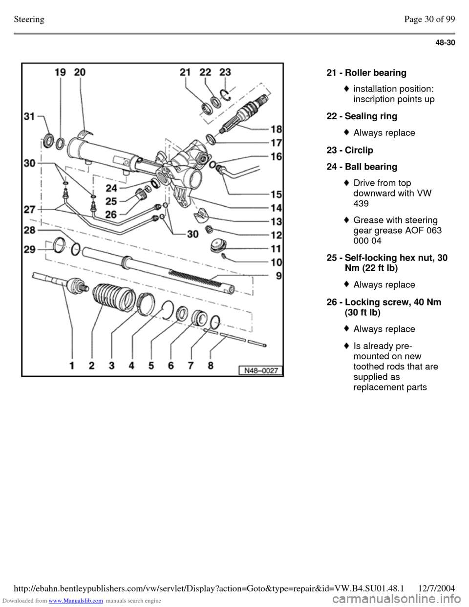
21 - Roller bearing installation position:
inscription points up
22 - Sealing ring Always replace 23 - Circlip
24 - Ball bearing Drive from top
downward with VW
439 Grease with steering
gear grease AOF 063
000 04
25 - Self-locking hex nut, 30 Nm (22 ft lb) Always replace 26 - Locking screw, 40 Nm
(30 ft lb) Always replace Is already pre-
mounted on new
toothed rods that are
supplied as
replacement parts Page 30 of 99Steering12/7/2004http://ebahn.bentleypublishers.com/vw/servlet/Display?action=Goto&type=repair&id=VW.B4.SU01.48.1
Page 301 of 369
Downloaded from www.Manualslib.com manuals search engine 48-31
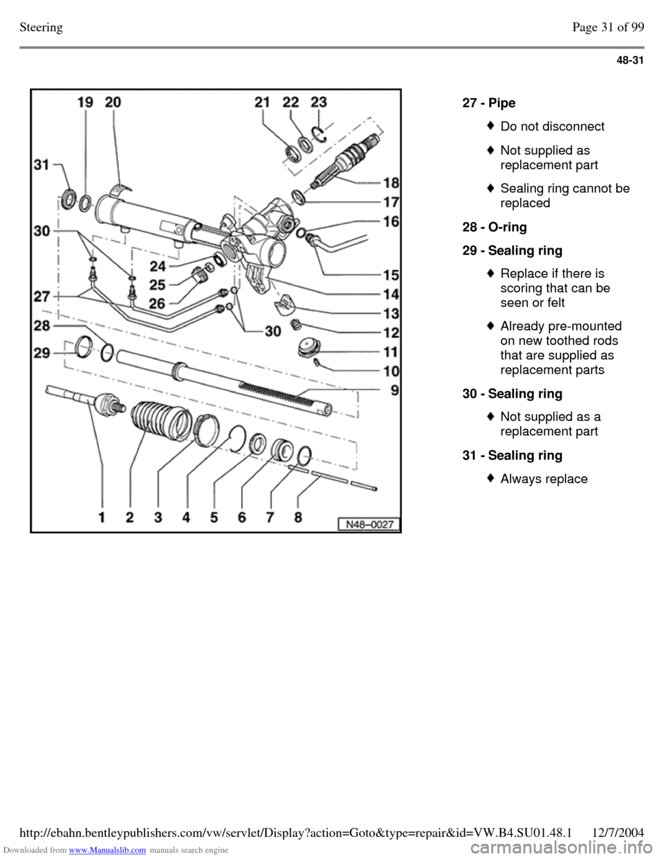
27 - Pipe Do not disconnect Not supplied as
replacement part Sealing ring cannot be
replaced
28 - O-ring
29 - Sealing ring Replace if there is
scoring that can be
seen or felt Already pre-mounted
on new toothed rods
that are supplied as
replacement parts
30 - Sealing ring Not supplied as a
replacement part
31 - Sealing ring Always replace Page 31 of 99Steering12/7/2004http://ebahn.bentleypublishers.com/vw/servlet/Display?action=Goto&type=repair&id=VW.B4.SU01.48.1
Page 302 of 369
Downloaded from www.Manualslib.com manuals search engine 48-32
Power steering gear, disassembling
- Tie rods, removing - see tie rod, removing and
installing (TRW and ZF power steering), Page 48-77
- Close hose connections on power steering gear
if not already done
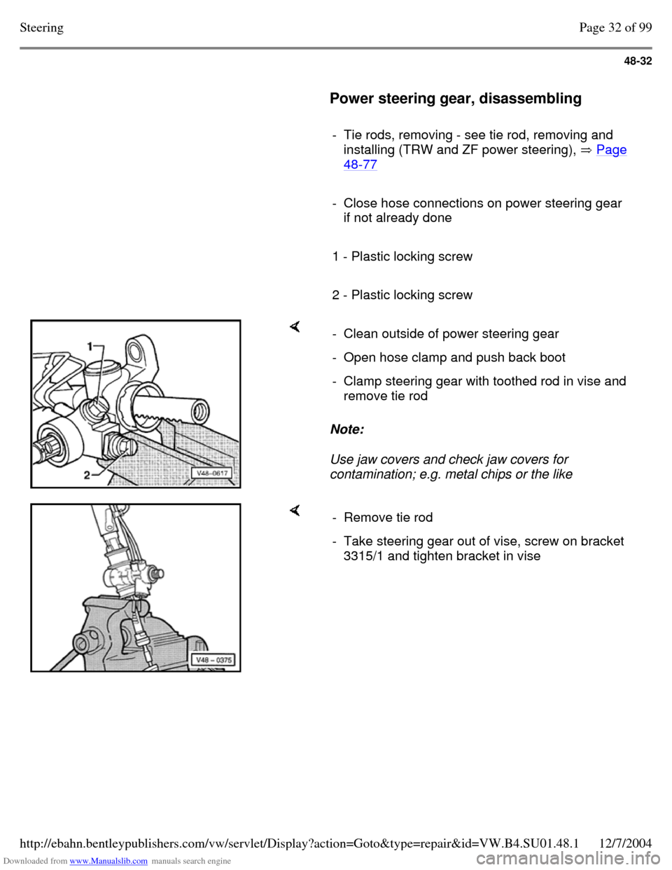
1 - Plastic locking screw
2 - Plastic locking screw Note:
Use jaw covers and check jaw covers for
contamination; e.g. metal chips or the like - Clean outside of power steering gear - Open hose clamp and push back boot - Clamp steering gear with toothed rod in vise and
remove tie rod - Remove tie rod - Take steering gear out of vise, screw on bracket
3315/1 and tighten bracket in vise Page 32 of 99Steering12/7/2004http://ebahn.bentleypublishers.com/vw/servlet/Display?action=Goto&type=repair&id=VW.B4.SU01.48.1
Page 303 of 369
Downloaded from www.Manualslib.com manuals search engine 48-33
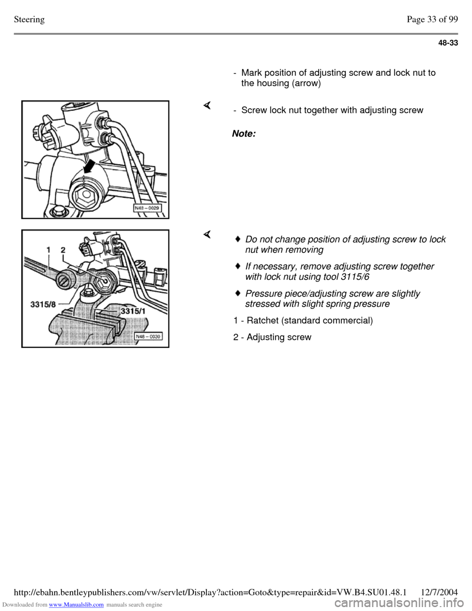
- Mark position of adjusting screw and lock nut to
the housing (arrow) Note: - Screw lock nut together with adjusting screw Do not change position of adjusting screw to lock
nut when removing If necessary, remove adjusting screw together
with lock nut using tool 3115/6 Pressure piece/adjusting screw are slightly
stressed with slight spring pressure
1 - Ratchet (standard commercial) 2 - Adjusting screw Page 33 of 99Steering12/7/2004http://ebahn.bentleypublishers.com/vw/servlet/Display?action=Goto&type=repair&id=VW.B4.SU01.48.1
Page 304 of 369
Downloaded from www.Manualslib.com manuals search engine 48-34
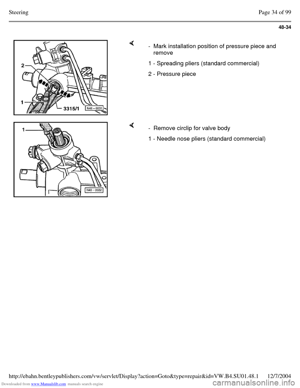
- Mark installation position of pressure piece and
remove
1 - Spreading pliers (standard commercial) 2 - Pressure piece - Remove circlip for valve body 1 - Needle nose pliers (standard commercial) Page 34 of 99Steering12/7/2004http://ebahn.bentleypublishers.com/vw/servlet/Display?action=Goto&type=repair&id=VW.B4.SU01.48.1
Page 305 of 369
Downloaded from www.Manualslib.com manuals search engine 48-35
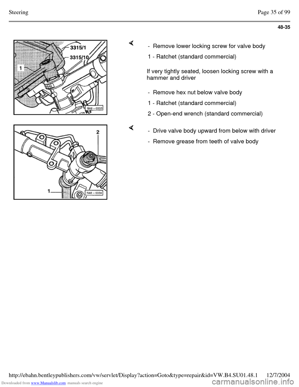
If very tightly seated, loosen locking screw with a
hammer and driver - Remove lower locking screw for valve body 1 - Ratchet (standard commercial) - Remove hex nut below valve body 1 - Ratchet (standard commercial) 2 - Open-end wrench (standard commercial) - Drive valve body upward from below with driver - Remove grease from teeth of valve body Page 35 of 99Steering12/7/2004http://ebahn.bentleypublishers.com/vw/servlet/Display?action=Goto&type=repair&id=VW.B4.SU01.48.1
Page 306 of 369
Downloaded from www.Manualslib.com manuals search engine 48-36
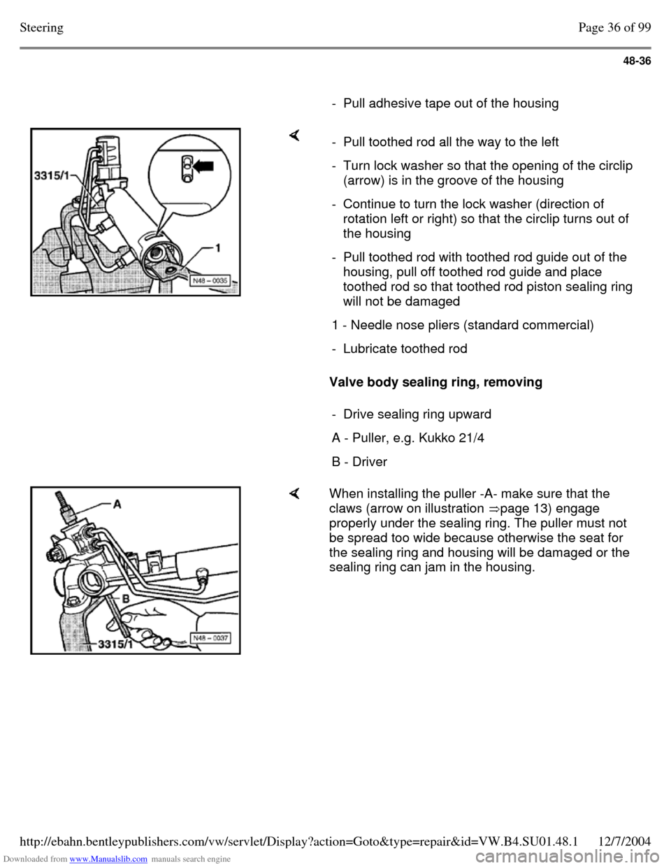
- Pull adhesive tape out of the housing Valve body sealing ring, removing - Pull toothed rod all the way to the left - Turn lock washer so that the opening of the circlip
(arrow) is in the groove of the housing
- Continue to turn the lock washer (direction of
rotation left or right) so that the circlip turns out of
the housing
- Pull toothed rod with toothed rod guide out of the
housing, pull off toothed rod guide and place
toothed rod so that toothed rod piston sealing ring
will not be damaged
1 - Needle nose pliers (standard commercial) - Lubricate toothed rod - Drive sealing ring upward A - Puller, e.g. Kukko 21/4 B - Driver When installing the puller -A- make sure that the
claws (arrow on illustration page 13) engage
properly under the sealing ring. The puller must not
be spread too wide because otherwise the seat for
the sealing ring and housing will be damaged or the
sealing ring can jam in the housing. Page 36 of 99Steering12/7/2004http://ebahn.bentleypublishers.com/vw/servlet/Display?action=Goto&type=repair&id=VW.B4.SU01.48.1
Page 307 of 369
Downloaded from www.Manualslib.com manuals search engine 48-37
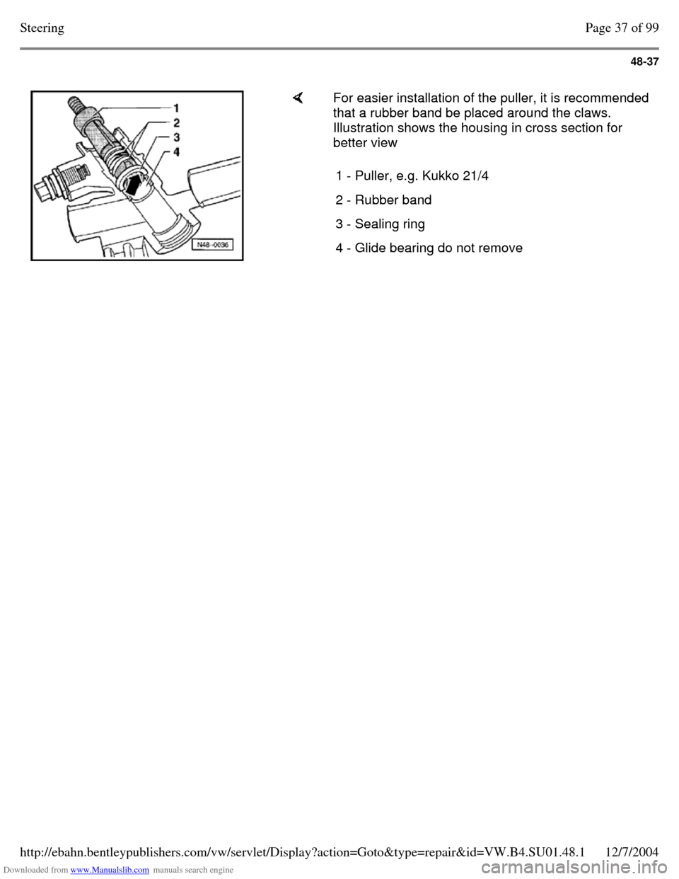
For easier installation of the puller, it is recommended
that a rubber band be placed around the claws.
Illustration shows the housing in cross section for
better view
1 - Puller, e.g. Kukko 21/4 2 - Rubber band 3 - Sealing ring 4 - Glide bearing do not remove Page 37 of 99Steering12/7/2004http://ebahn.bentleypublishers.com/vw/servlet/Display?action=Goto&type=repair&id=VW.B4.SU01.48.1
Page 308 of 369
Downloaded from www.Manualslib.com manuals search engine 48-38
Inner sealing ring for toothed rod,
pulling out
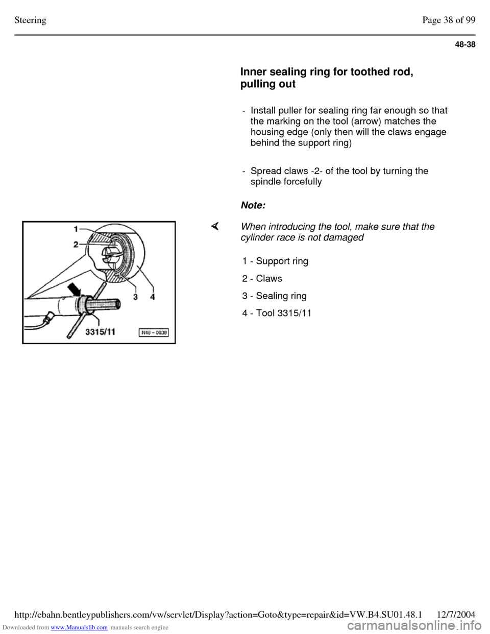
- Install puller for sealing ring far enough so that
the marking on the tool (arrow) matches the
housing edge (only then will the claws engage
behind the support ring)
- Spread claws -2- of the tool by turning the
spindle forcefully
Note: When introducing the tool, make sure that the
cylinder race is not damaged
1 - Support ring 2 - Claws 3 - Sealing ring 4 - Tool 3315/11 Page 38 of 99Steering12/7/2004http://ebahn.bentleypublishers.com/vw/servlet/Display?action=Goto&type=repair&id=VW.B4.SU01.48.1