VOLKSWAGEN PASSAT 1995 B3, B4 / 3.G Service Owner's Guide
PASSAT 1995 B3, B4 / 3.G
VOLKSWAGEN
VOLKSWAGEN
https://www.carmanualsonline.info/img/18/7419/w960_7419-0.png
VOLKSWAGEN PASSAT 1995 B3, B4 / 3.G Service Owner's Guide
Page 37 of 369
Downloaded from www.Manualslib.com manuals search engine 40-23
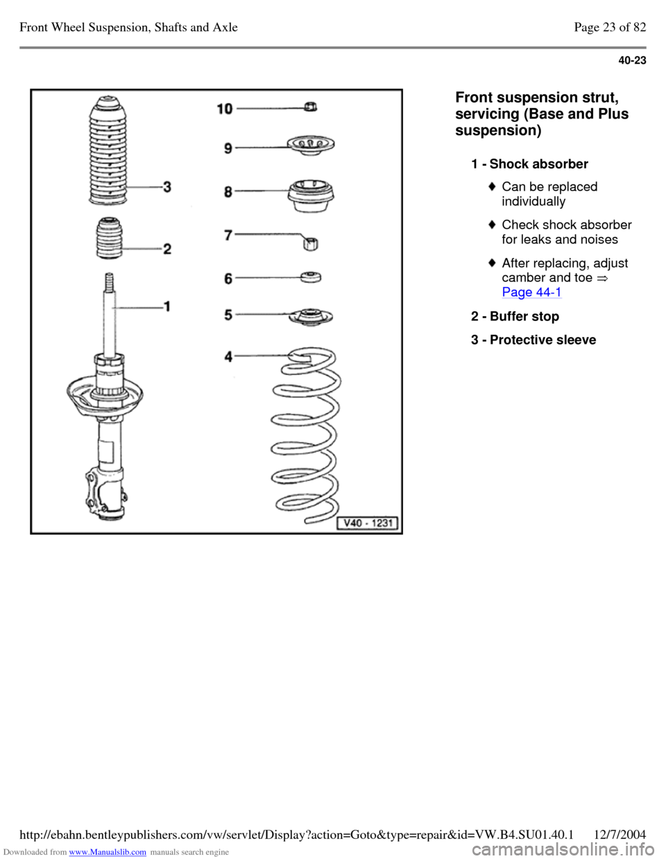
Front suspension strut,
servicing (Base and Plus
suspension)
1 - Shock absorber Can be replaced
individually Check shock absorber
for leaks and noises After replacing, adjust
camber and toe
Page 44-1 2 - Buffer stop
3 - Protective sleeve Page 23 of 82Front Wheel Suspension, Shafts and Axle12/7/2004http://ebahn.bentleypublishers.com/vw/servlet/Display?action=Goto&type=repair&id=VW.B4.SU01.40.1
Page 38 of 369
Downloaded from www.Manualslib.com manuals search engine 40-24
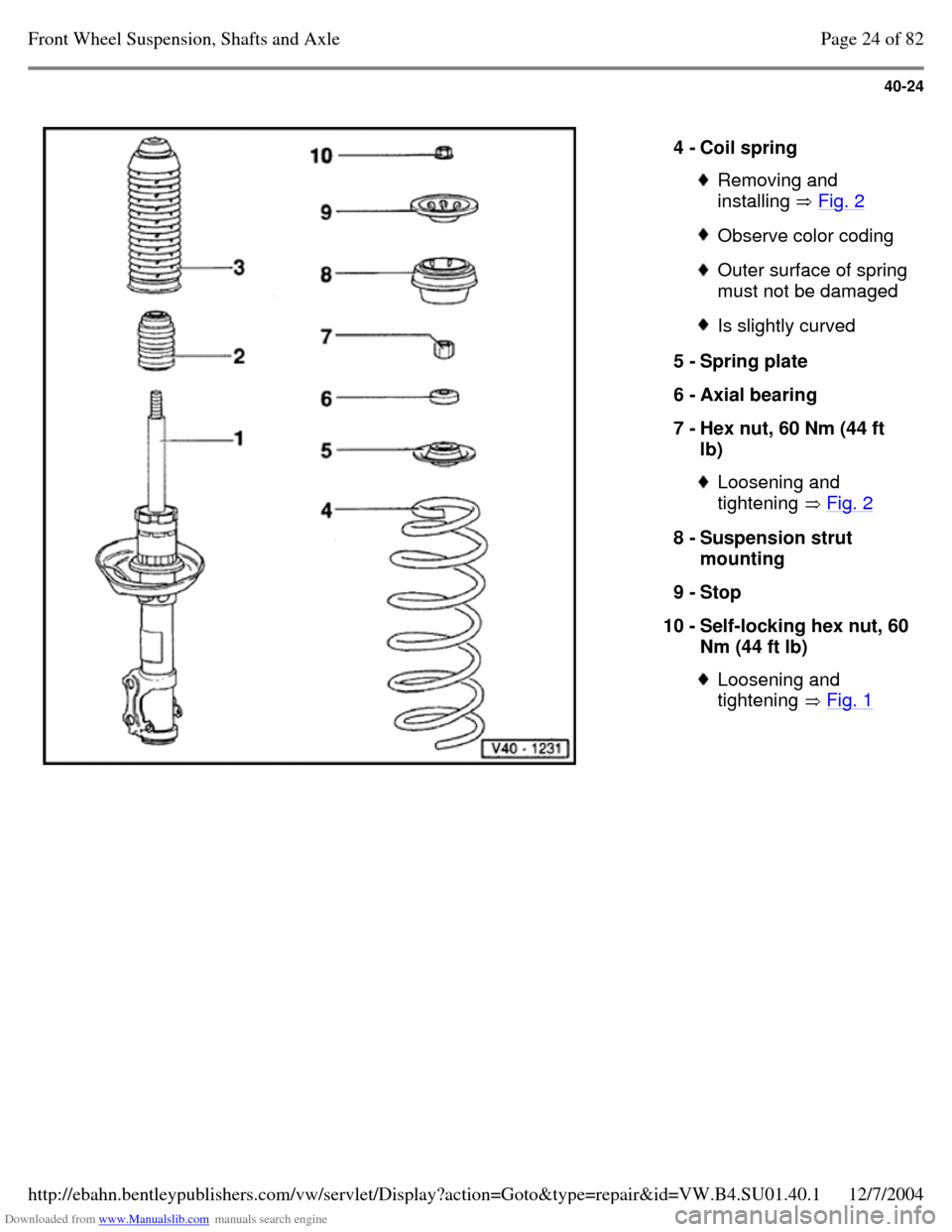
4 - Coil spring Removing and
installing Fig. 2 Observe color coding Outer surface of spring must not be damaged Is slightly curved 5 - Spring plate
6 - Axial bearing
7 - Hex nut, 60 Nm (44 ft
lb) Loosening and
tightening Fig. 2 8 - Suspension strut
mounting
9 - Stop
10 - Self-locking hex nut, 60 Nm (44 ft lb) Loosening and
tightening Fig. 1 Page 24 of 82Front Wheel Suspension, Shafts and Axle12/7/2004http://ebahn.bentleypublishers.com/vw/servlet/Display?action=Goto&type=repair&id=VW.B4.SU01.40.1
Page 39 of 369
Downloaded from www.Manualslib.com manuals search engine 40-25
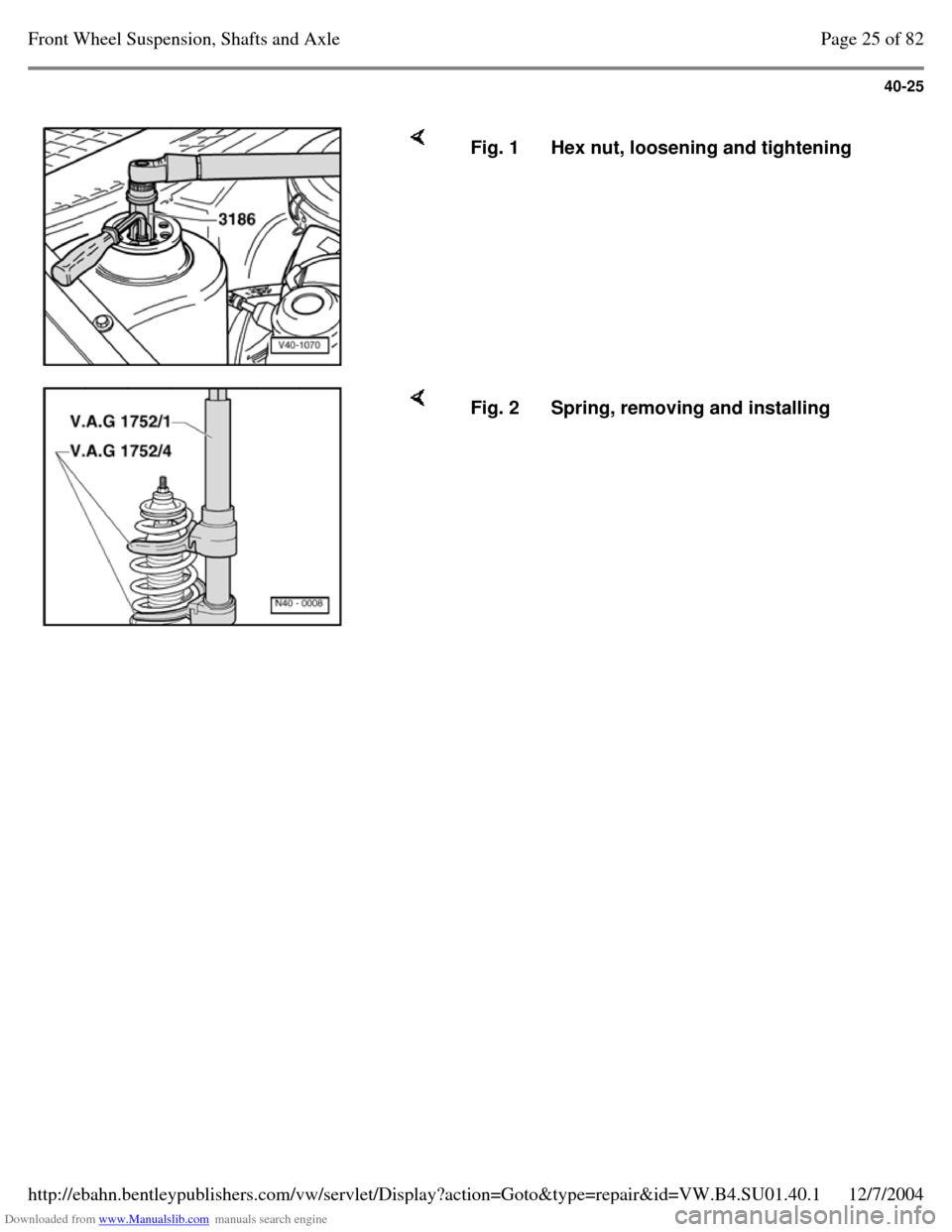
Fig. 1 Hex nut, loosening and tightening Fig. 2 Spring, removing and installing Page 25 of 82Front Wheel Suspension, Shafts and Axle12/7/2004http://ebahn.bentleypublishers.com/vw/servlet/Display?action=Goto&type=repair&id=VW.B4.SU01.40.1
Page 40 of 369
Downloaded from www.Manualslib.com manuals search engine 40-26
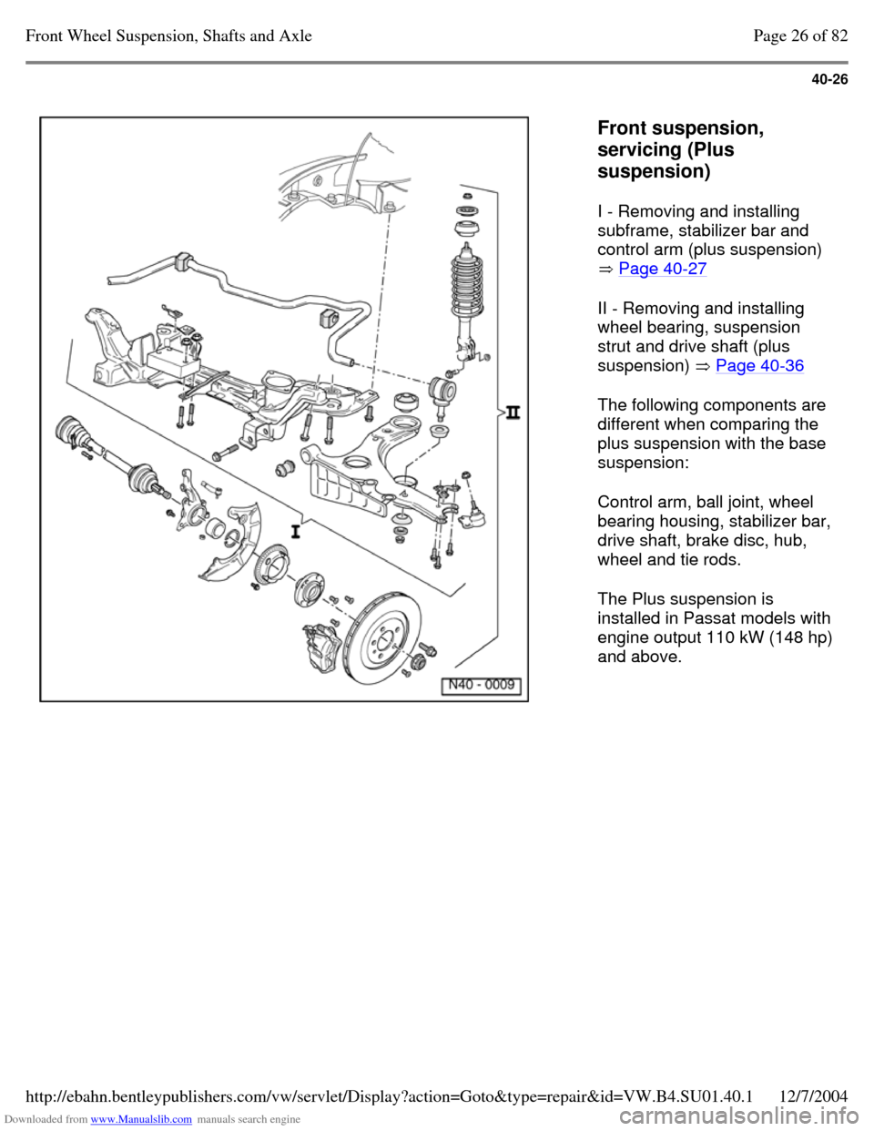
Front suspension,
servicing (Plus
suspension)
I - Removing and installing
subframe, stabilizer bar and
control arm (plus suspension)
Page 40-27
II - Removing and installing
wheel bearing, suspension
strut and drive shaft (plus
suspension) Page 40-36
The following components are
different when comparing the
plus suspension with the base
suspension:
Control arm, ball joint, wheel
bearing housing, stabilizer bar,
drive shaft, brake disc, hub,
wheel and tie rods.
The Plus suspension is
installed in Passat models with
engine output 110 kW (148 hp)
and above. Page 26 of 82Front Wheel Suspension, Shafts and Axle12/7/2004http://ebahn.bentleypublishers.com/vw/servlet/Display?action=Goto&type=repair&id=VW.B4.SU01.40.1
Page 41 of 369
Downloaded from www.Manualslib.com manuals search engine 40-27
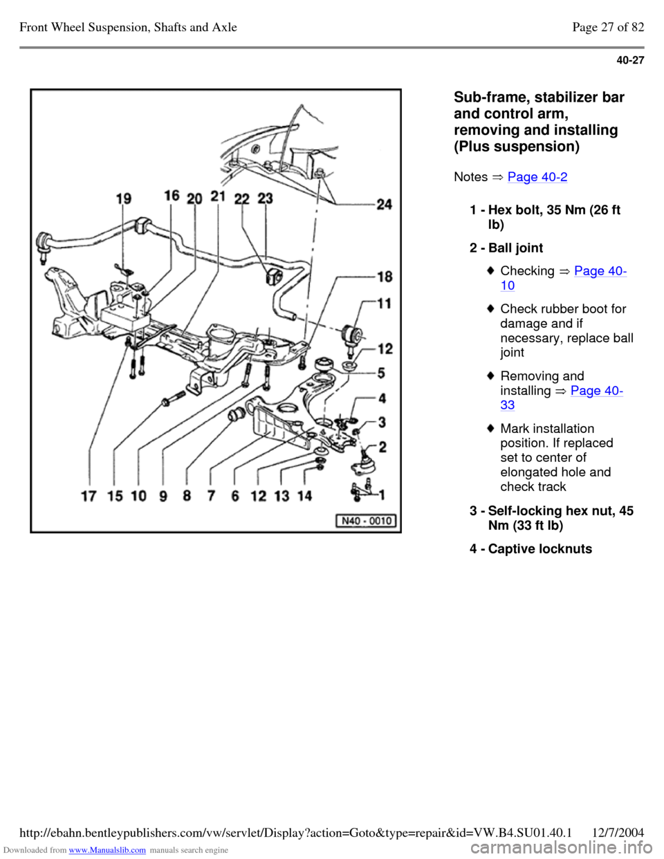
Sub-frame, stabilizer bar
and control arm,
removing and installing
(Plus suspension)
Notes Page 40-2 1 - Hex bolt, 35 Nm (26 ft
lb)
2 - Ball joint Checking Page 40-10 Check rubber boot for
damage and if necessary, replace ball joint Removing and
installing Page 40-33 Mark installation
position. If replaced
set to center of
elongated hole and
check track
3 - Self-locking hex nut, 45 Nm (33 ft lb)
4 - Captive locknuts Page 27 of 82Front Wheel Suspension, Shafts and Axle12/7/2004http://ebahn.bentleypublishers.com/vw/servlet/Display?action=Goto&type=repair&id=VW.B4.SU01.40.1
Page 42 of 369
Downloaded from www.Manualslib.com manuals search engine 40-28
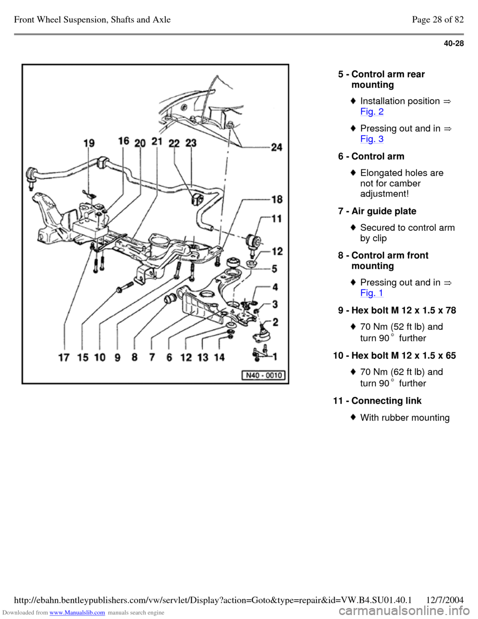
5 - Control arm rear
mounting Installation position
Fig. 2 Pressing out and in
Fig. 3 6 - Control arm Elongated holes are
not for camber
adjustment!
7 - Air guide plate Secured to control arm by clip
8 - Control arm front
mounting Pressing out and in
Fig. 1 9 - Hex bolt M 12 x 1.5 x 78 70 Nm (52 ft lb) and
turn 90 further 10 - Hex bolt M 12 x 1.5 x 65 70 Nm (62 ft lb) and
turn 90 further 11 - Connecting link With rubber mounting Page 28 of 82Front Wheel Suspension, Shafts and Axle12/7/2004http://ebahn.bentleypublishers.com/vw/servlet/Display?action=Goto&type=repair&id=VW.B4.SU01.40.1
Page 43 of 369
Downloaded from www.Manualslib.com manuals search engine 40-29
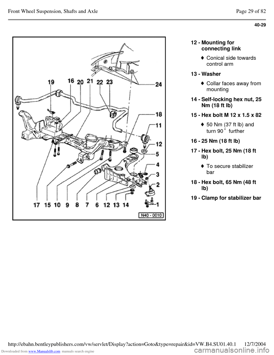
12 - Mounting for
connecting link Conical side towards
control arm
13 - Washer Collar faces away from mounting
14 - Self-locking hex nut, 25 Nm (18 ft lb)
15 - Hex bolt M 12 x 1.5 x 82 50 Nm (37 ft lb) and
turn 90 further 16 - 25 Nm (18 ft lb)
17 - Hex bolt, 25 Nm (18 ft
lb) To secure stabilizer
bar
18 - Hex bolt, 65 Nm (48 ft
lb)
19 - Clamp for stabilizer bar Page 29 of 82Front Wheel Suspension, Shafts and Axle12/7/2004http://ebahn.bentleypublishers.com/vw/servlet/Display?action=Goto&type=repair&id=VW.B4.SU01.40.1
Page 44 of 369
Downloaded from www.Manualslib.com manuals search engine 40-30
Repair Manual, Engine
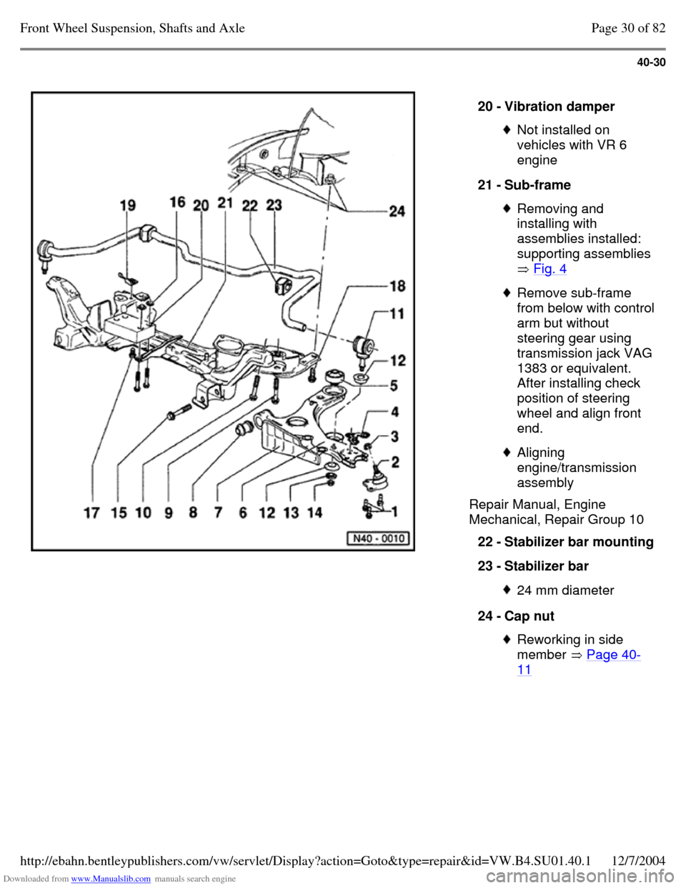
Mechanical, Repair Group 10 20 - Vibration damper Not installed on
vehicles with VR 6
engine
21 - Sub-frame Removing and
installing with
assemblies installed:
supporting assemblies
Fig. 4 Remove sub-frame from below with control arm but without
steering gear using transmission jack VAG 1383 or equivalent.
After installing check
position of steering
wheel and align front
end. Aligning
engine/transmission
assembly
22 - Stabilizer bar mounting 23 - Stabilizer bar 24 mm diameter 24 - Cap nut Reworking in side
member Page 40-11 Page 30 of 82Front Wheel Suspension, Shafts and Axle12/7/2004http://ebahn.bentleypublishers.com/vw/servlet/Display?action=Goto&type=repair&id=VW.B4.SU01.40.1
Page 45 of 369
Downloaded from www.Manualslib.com manuals search engine 40-31
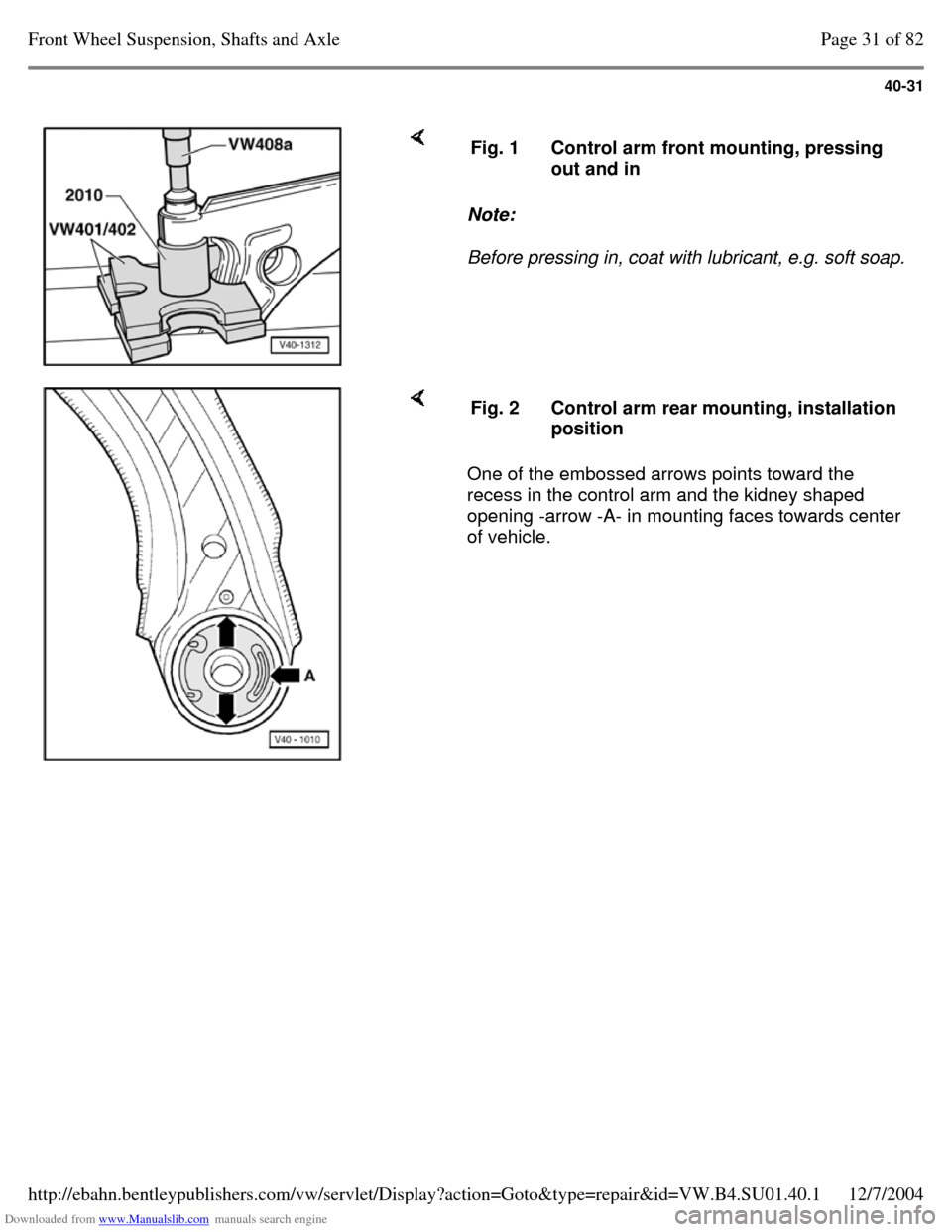
Note:
Before pressing in, coat with lubricant, e.g. soft soap. Fig. 1 Control arm front mounting, pressing
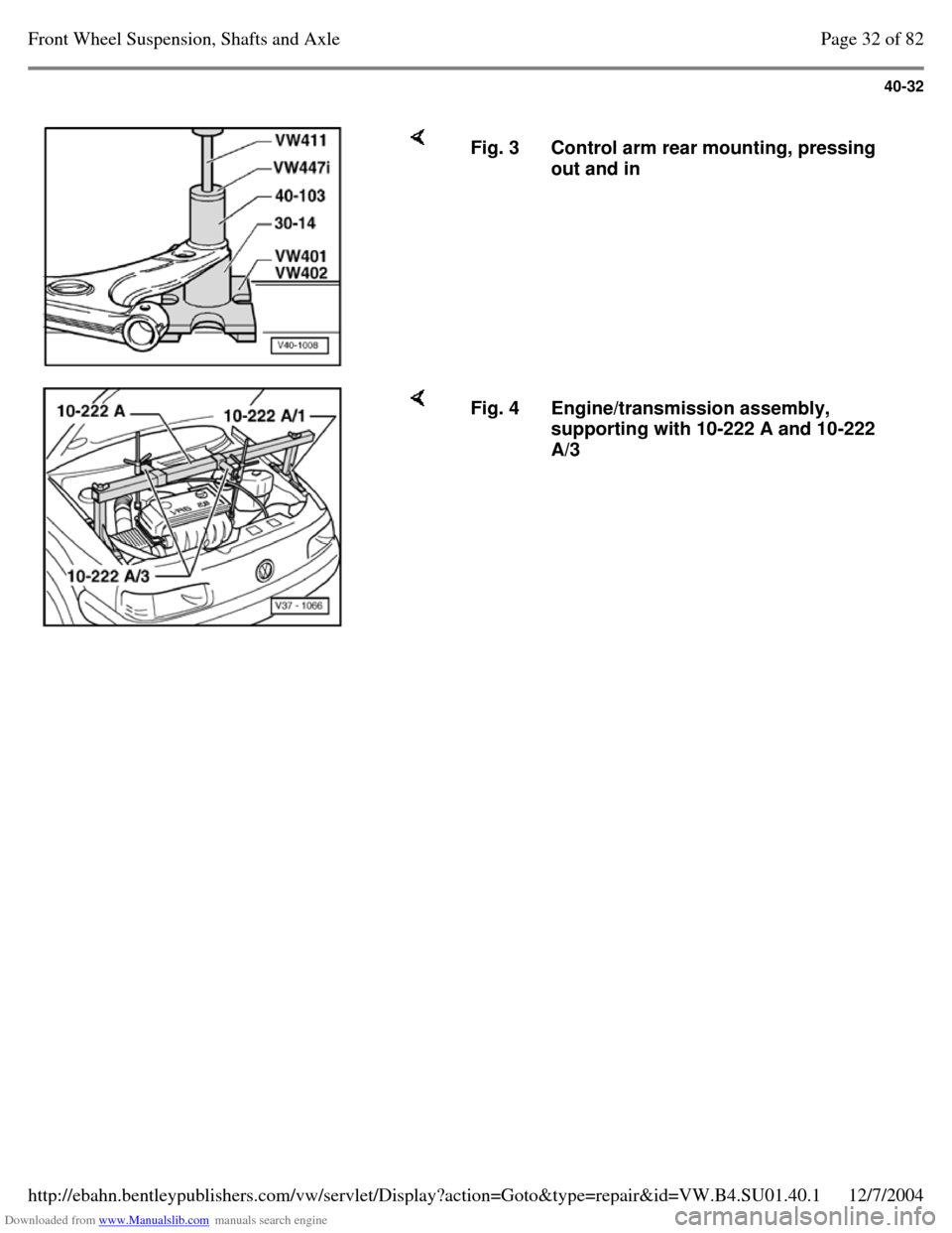
out and in One of the embossed arrows points toward the
recess in the control arm and the kidney shaped
opening -arrow -A- in mounting faces towards center
of vehicle. Fig. 2 Control arm rear mounting, installation
position Page 31 of 82Front Wheel Suspension, Shafts and Axle12/7/2004http://ebahn.bentleypublishers.com/vw/servlet/Display?action=Goto&type=repair&id=VW.B4.SU01.40.1
Page 46 of 369
Downloaded from www.Manualslib.com manuals search engine 40-32
Fig. 3 Control arm rear mounting, pressing
out and in Fig. 4 Engine/transmission assembly,
supporting with 10-222 A and 10-222
A/3 Page 32 of 82Front Wheel Suspension, Shafts and Axle12/7/2004http://ebahn.bentleypublishers.com/vw/servlet/Display?action=Goto&type=repair&id=VW.B4.SU01.40.1
