display VOLKSWAGEN PASSAT 1995 B3, B4 / 3.G Service Manual PDF
[x] Cancel search | Manufacturer: VOLKSWAGEN, Model Year: 1995, Model line: PASSAT, Model: VOLKSWAGEN PASSAT 1995 B3, B4 / 3.GPages: 369, PDF Size: 12.33 MB
Page 77 of 369
Downloaded from www.Manualslib.com manuals search engine 40-63
Note:
Excessive backlash in joint will be noticed as a
knock during load changes. In such cases the
joint must be replaced. Polished areas and ball
track marks are not a reason for changing the
joint.
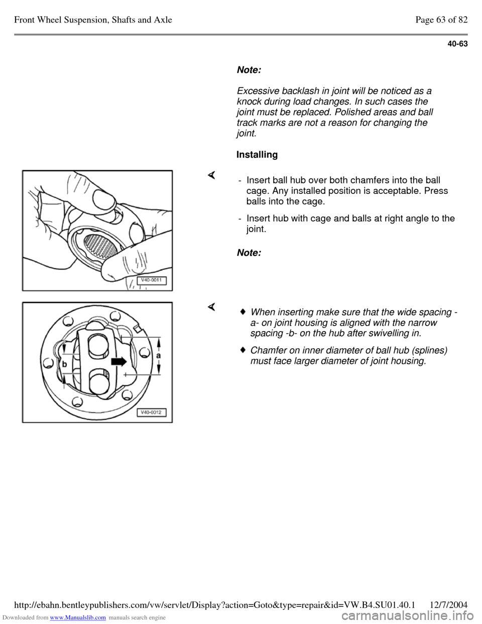
Installing Note: - Insert ball hub over both chamfers into the ball
cage. Any installed position is acceptable. Press
balls into the cage.
- Insert hub with cage and balls at right angle to the
joint. When inserting make sure that the wide spacing -
a- on joint housing is aligned with the narrow
spacing -b- on the hub after swivelling in. Chamfer on inner diameter of ball hub (splines)
must face larger diameter of joint housing. Page 63 of 82Front Wheel Suspension, Shafts and Axle12/7/2004http://ebahn.bentleypublishers.com/vw/servlet/Display?action=Goto&type=repair&id=VW.B4.SU01.40.1
Page 78 of 369
Downloaded from www.Manualslib.com manuals search engine 40-64
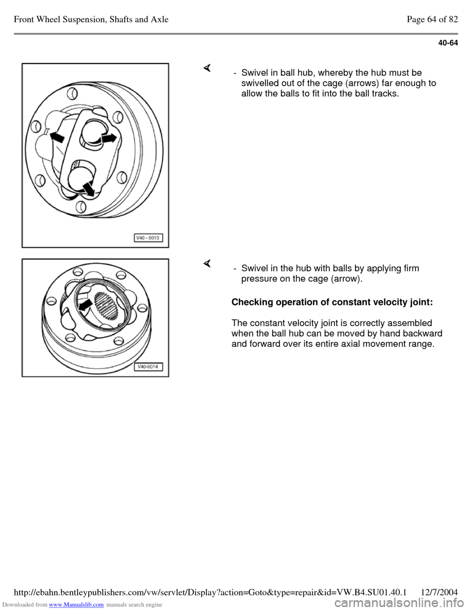
- Swivel in ball hub, whereby the hub must be
swivelled out of the cage (arrows) far enough to
allow the balls to fit into the ball tracks. Checking operation of constant velocity joint:
The constant velocity joint is correctly assembled
when the ball hub can be moved by hand backward
and forward over its entire axial movement range. - Swivel in the hub with balls by applying firm
pressure on the cage (arrow). Page 64 of 82Front Wheel Suspension, Shafts and Axle12/7/2004http://ebahn.bentleypublishers.com/vw/servlet/Display?action=Goto&type=repair&id=VW.B4.SU01.40.1
Page 79 of 369
Downloaded from www.Manualslib.com manuals search engine 40-65
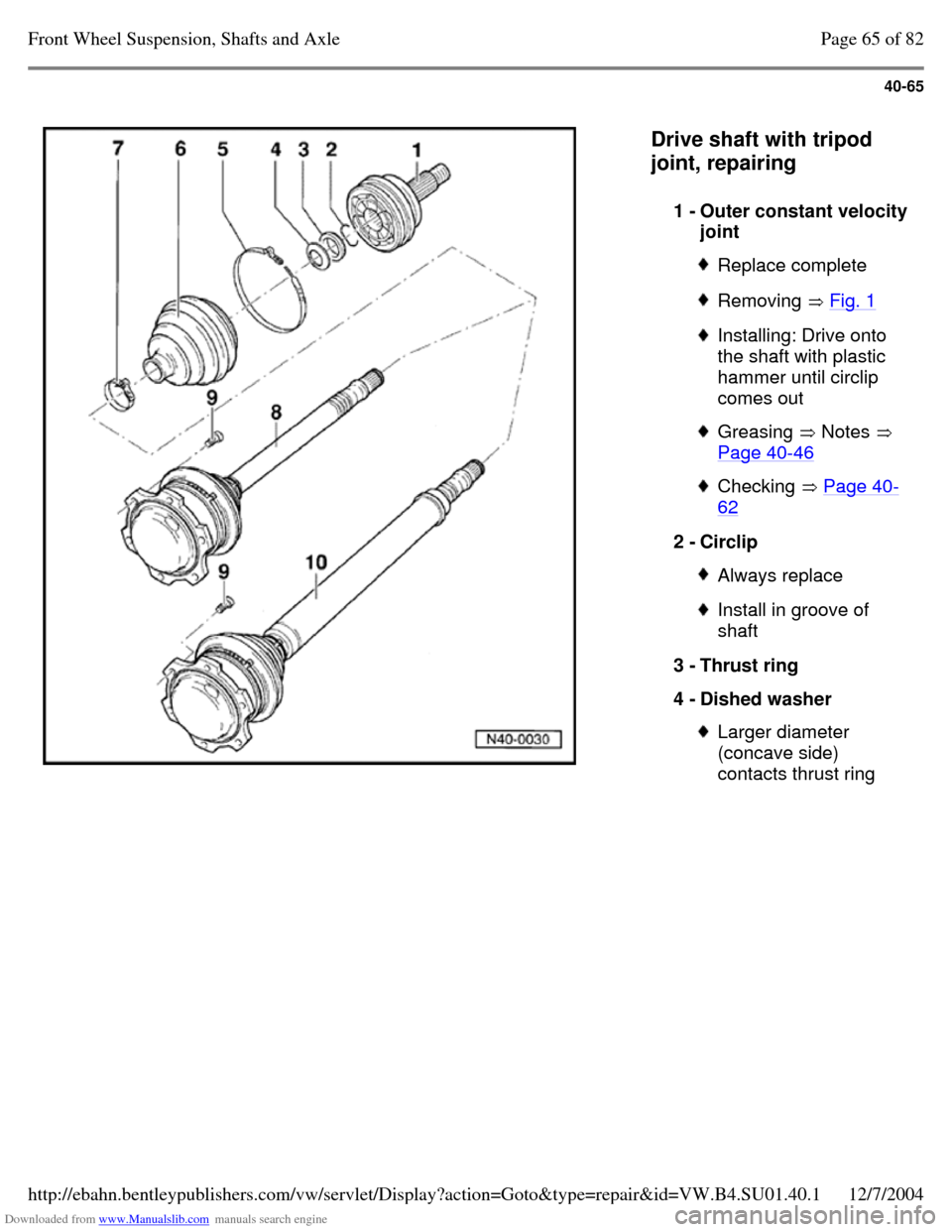
Drive shaft with tripod
joint, repairing
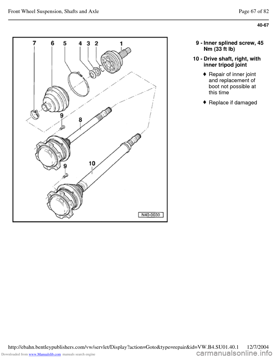
1 - Outer constant velocity joint Replace complete Removing Fig. 1 Installing: Drive onto
the shaft with plastic
hammer until circlip
comes out Greasing Notes
Page 40-46 Checking Page 40-62 2 - Circlip Always replace Install in groove of
shaft
3 - Thrust ring
4 - Dished washer Larger diameter
(concave side)
contacts thrust ring Page 65 of 82Front Wheel Suspension, Shafts and Axle12/7/2004http://ebahn.bentleypublishers.com/vw/servlet/Display?action=Goto&type=repair&id=VW.B4.SU01.40.1
Page 80 of 369
Downloaded from www.Manualslib.com manuals search engine 40-66
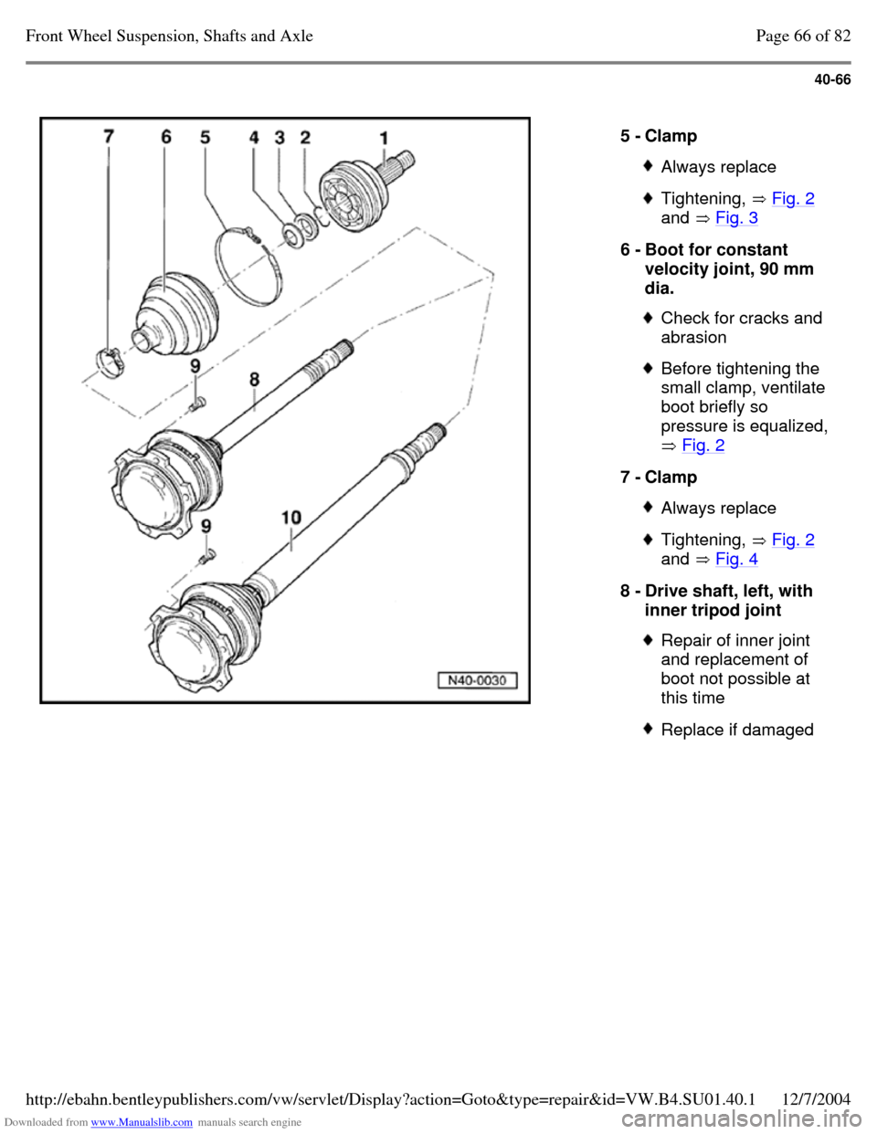
5 - Clamp Always replace Tightening, Fig. 2
and Fig. 3 6 - Boot for constant
velocity joint, 90 mm
dia. Check for cracks and
abrasion Before tightening the
small clamp, ventilate
boot briefly so
pressure is equalized,
Fig. 2 7 - Clamp Always replace Tightening, Fig. 2
and Fig. 4 8 - Drive shaft, left, with
inner tripod joint Repair of inner joint
and replacement of
boot not possible at
this time Replace if damaged Page 66 of 82Front Wheel Suspension, Shafts and Axle12/7/2004http://ebahn.bentleypublishers.com/vw/servlet/Display?action=Goto&type=repair&id=VW.B4.SU01.40.1
Page 81 of 369
Downloaded from www.Manualslib.com manuals search engine 40-67
9 - Inner splined screw, 45 Nm (33 ft lb)
10 - Drive shaft, right, with
inner tripod joint Repair of inner joint
and replacement of
boot not possible at
this time Replace if damaged Page 67 of 82Front Wheel Suspension, Shafts and Axle12/7/2004http://ebahn.bentleypublishers.com/vw/servlet/Display?action=Goto&type=repair&id=VW.B4.SU01.40.1
Page 82 of 369
Downloaded from www.Manualslib.com manuals search engine 40-68
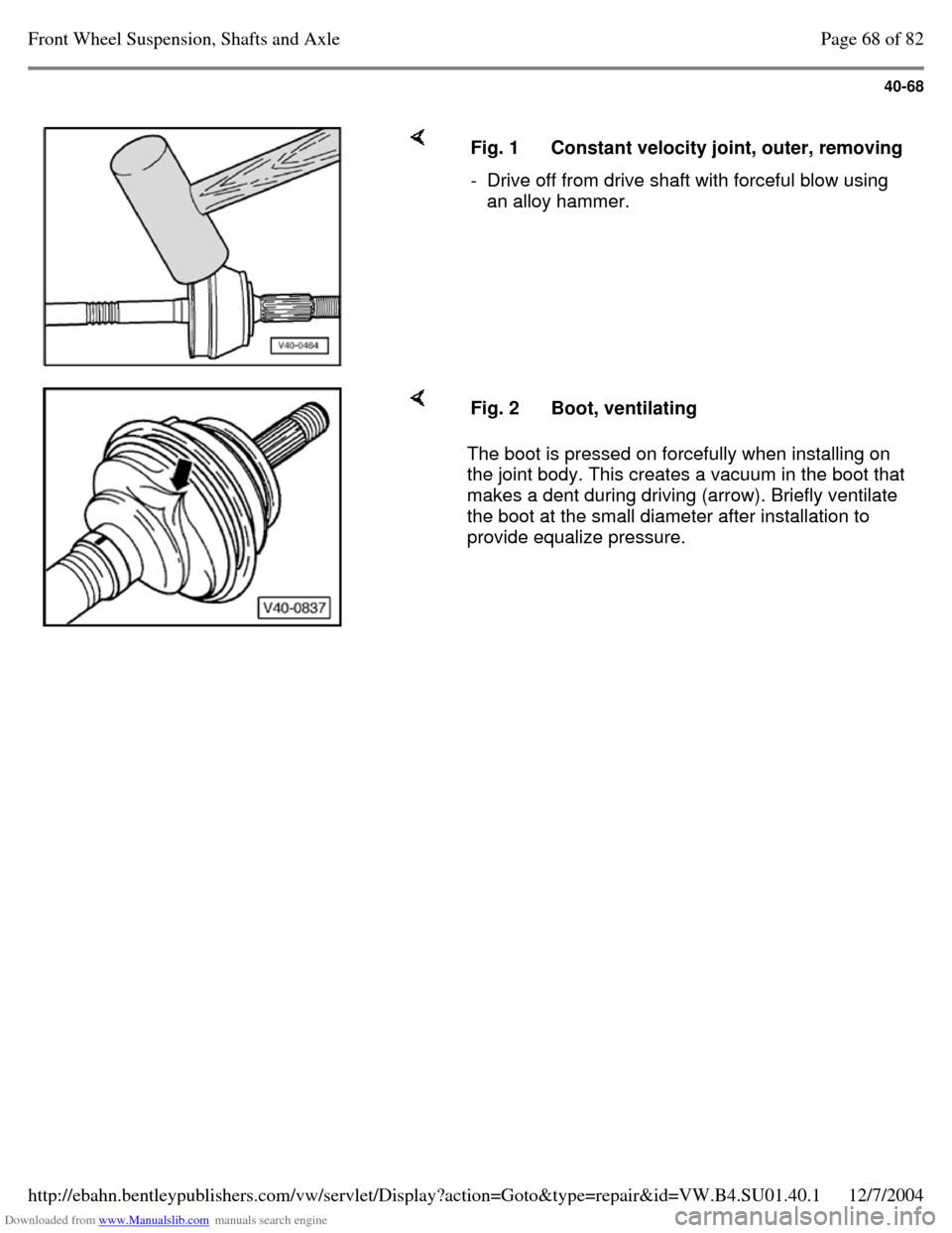
Fig. 1 Constant velocity joint, outer, removing - Drive off from drive shaft with forceful blow using
an alloy hammer. The boot is pressed on forcefully when installing on
the joint body. This creates a vacuum in the boot that
makes a dent during driving (arrow). Briefly ventilate
the boot at the small diameter after installation to
provide equalize pressure. Fig. 2 Boot, ventilating Page 68 of 82Front Wheel Suspension, Shafts and Axle12/7/2004http://ebahn.bentleypublishers.com/vw/servlet/Display?action=Goto&type=repair&id=VW.B4.SU01.40.1
Page 83 of 369
Downloaded from www.Manualslib.com manuals search engine 40-69
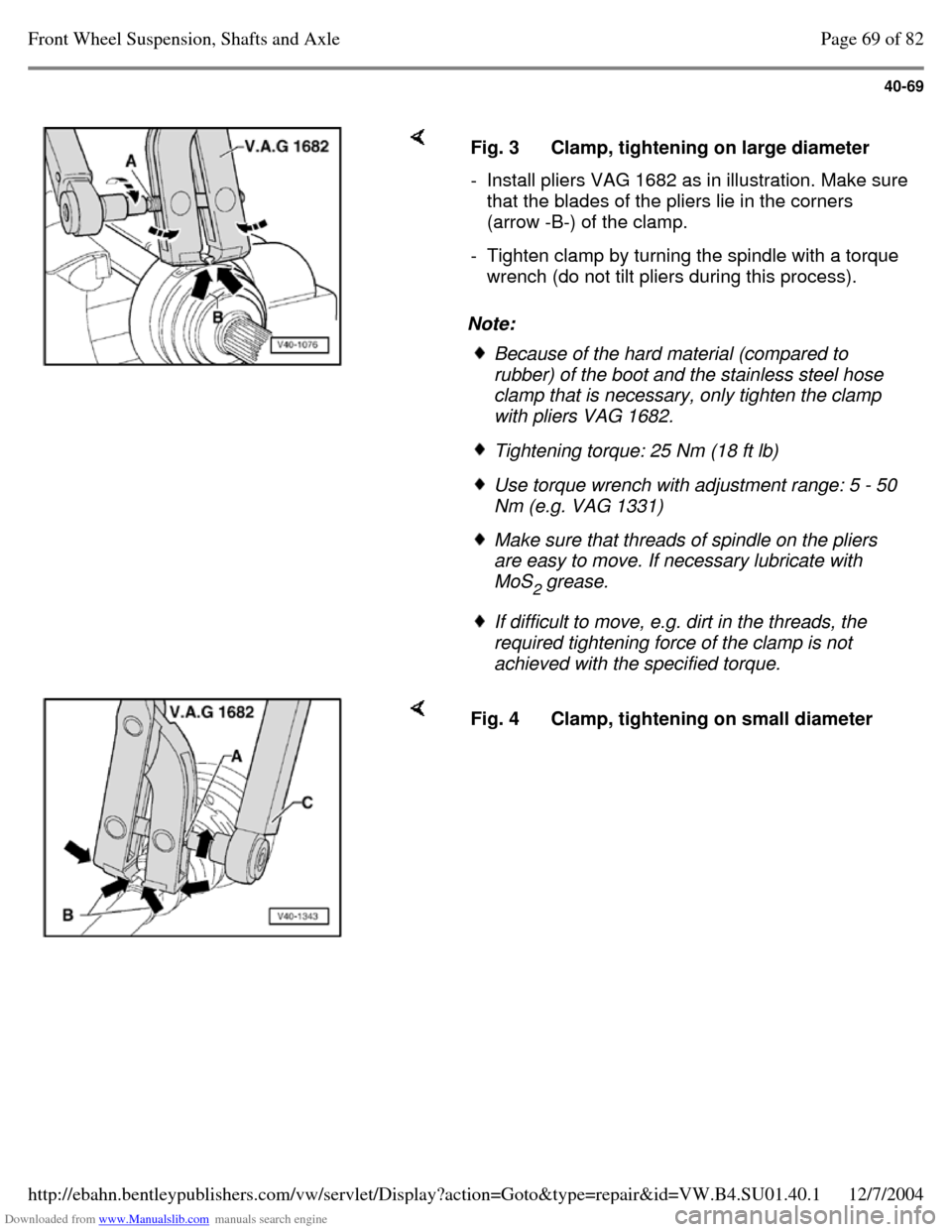
Note: Fig. 3 Clamp, tightening on large diameter - Install pliers VAG 1682 as in illustration. Make sure that the blades of the pliers lie in the corners
(arrow -B-) of the clamp.
- Tighten clamp by turning the spindle with a torque
wrench (do not tilt pliers during this process). Because of the hard material (compared to
rubber) of the boot and the stainless steel hose
clamp that is necessary, only tighten the clamp
with pliers VAG 1682. Tightening torque: 25 Nm (18 ft lb) Use torque wrench with adjustment range: 5 - 50
Nm (e.g. VAG 1331) Make sure that threads of spindle on the pliers
are easy to move. If necessary lubricate with
MoS
2 grease. If difficult to move, e.g. dirt in the threads, the
required tightening force of the clamp is not
achieved with the specified torque. Fig. 4 Clamp, tightening on small diameter Page 69 of 82Front Wheel Suspension, Shafts and Axle12/7/2004http://ebahn.bentleypublishers.com/vw/servlet/Display?action=Goto&type=repair&id=VW.B4.SU01.40.1
Page 84 of 369
Downloaded from www.Manualslib.com manuals search engine 40-70
Drive axle with triple-rotor joint,
removing and installing
Removing right-side drive axle
The right drive axle removal instructions remain
unchanged from the current repair manual
procedure.
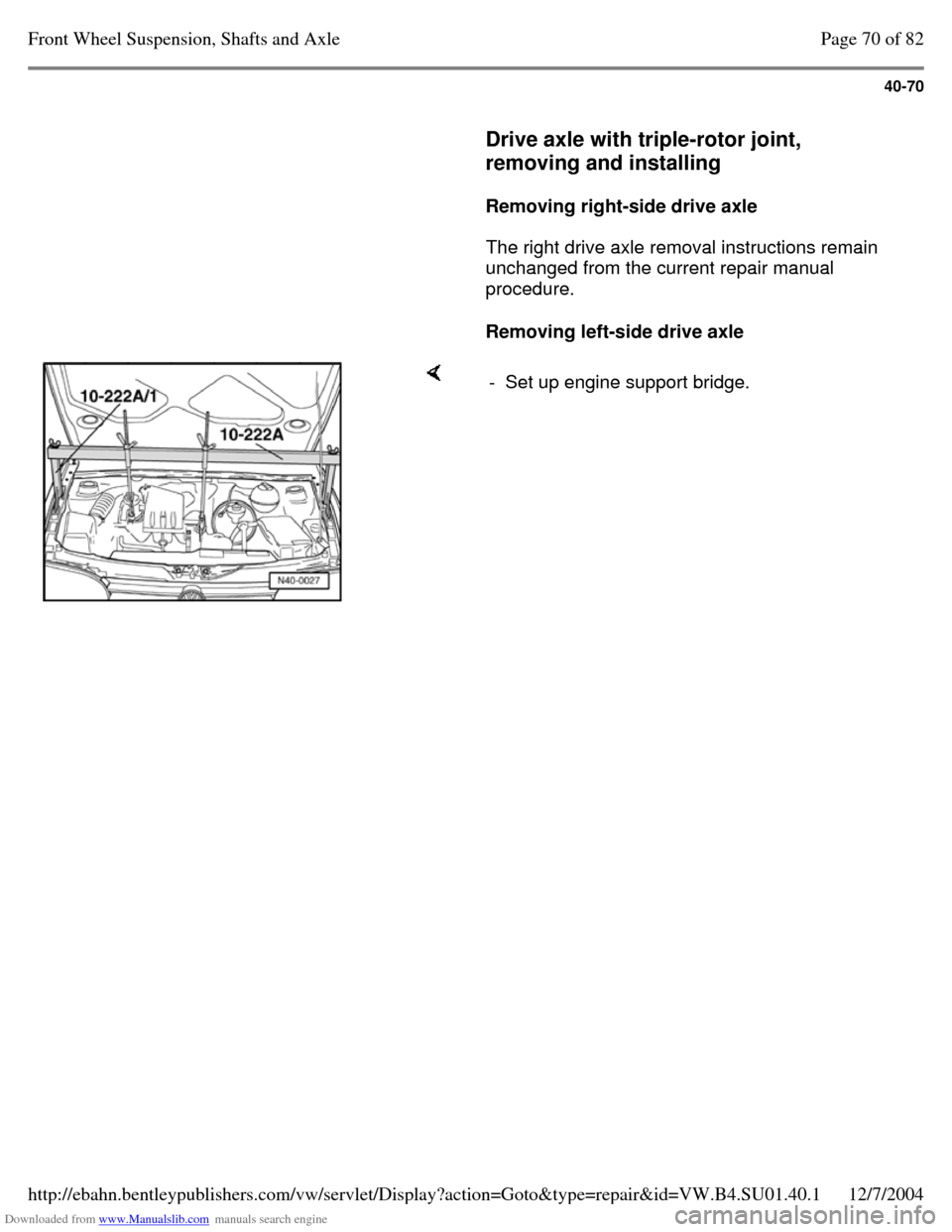
Removing left-side drive axle - Set up engine support bridge. Page 70 of 82Front Wheel Suspension, Shafts and Axle12/7/2004http://ebahn.bentleypublishers.com/vw/servlet/Display?action=Goto&type=repair&id=VW.B4.SU01.40.1
Page 85 of 369
Downloaded from www.Manualslib.com manuals search engine 40-71
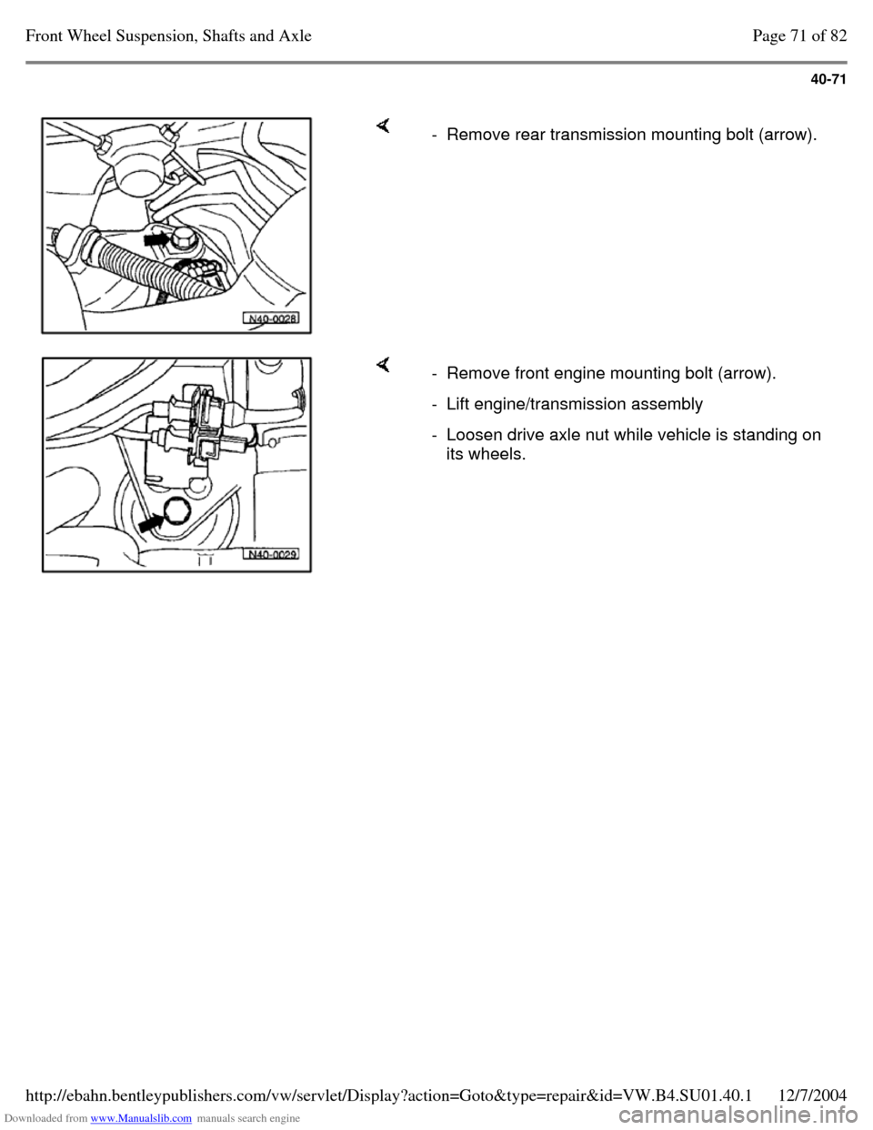
- Remove rear transmission mounting bolt (arrow). - Remove front engine mounting bolt (arrow). - Lift engine/transmission assembly - Loosen drive axle nut while vehicle is standing on
its wheels. Page 71 of 82Front Wheel Suspension, Shafts and Axle12/7/2004http://ebahn.bentleypublishers.com/vw/servlet/Display?action=Goto&type=repair&id=VW.B4.SU01.40.1
Page 86 of 369
Downloaded from www.Manualslib.com manuals search engine 40-72
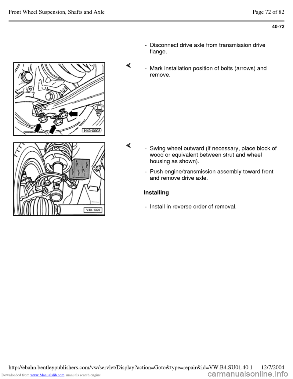
- Disconnect drive axle from transmission drive
flange. - Mark installation position of bolts (arrows) and
remove. Installing - Swing wheel outward (if necessary, place block of
wood or equivalent between strut and wheel
housing as shown).
- Push engine/transmission assembly toward front
and remove drive axle.
- Install in reverse order of removal. Page 72 of 82Front Wheel Suspension, Shafts and Axle12/7/2004http://ebahn.bentleypublishers.com/vw/servlet/Display?action=Goto&type=repair&id=VW.B4.SU01.40.1