ECU VOLKSWAGEN PASSAT 1996 B3, B4 / 3.G Service User Guide
[x] Cancel search | Manufacturer: VOLKSWAGEN, Model Year: 1996, Model line: PASSAT, Model: VOLKSWAGEN PASSAT 1996 B3, B4 / 3.GPages: 369, PDF Size: 12.33 MB
Page 94 of 369
Downloaded from www.Manualslib.com manuals search engine 40-80
Triple-rotor joint, assembling
- Slide small diameter boot clamp onto shaft.
- Slide triple-rotor joint boot onto shaft.
- Slide triple-rotor joint housing onto shaft.
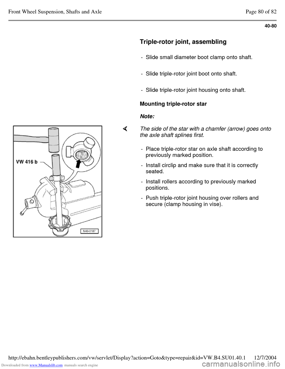
Mounting triple-rotor star
Note: The side of the star with a chamfer (arrow) goes onto
the axle shaft splines first.
- Place triple-rotor star on axle shaft according to
previously marked position.
- Install circlip and make sure that it is correctly
seated.
- Install rollers according to previously marked
positions.
- Push triple-rotor joint housing over rollers and
secure (clamp housing in vise). Page 80 of 82Front Wheel Suspension, Shafts and Axle12/7/2004http://ebahn.bentleypublishers.com/vw/servlet/Display?action=Goto&type=repair&id=VW.B4.SU01.40.1
Page 96 of 369
Downloaded from www.Manualslib.com manuals search engine 40-82
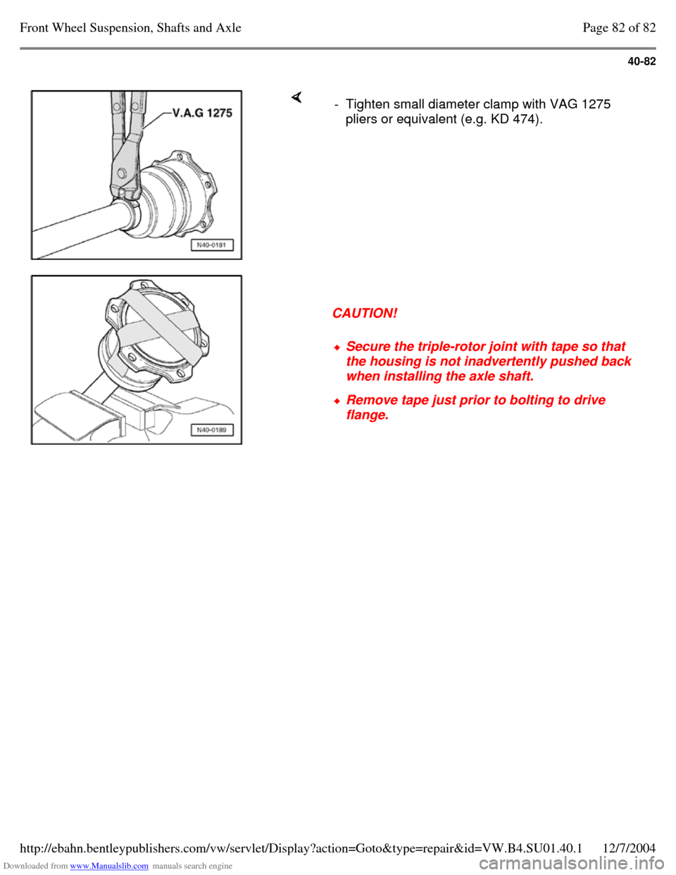
- Tighten small diameter clamp with VAG 1275
pliers or equivalent (e.g. KD 474).
CAUTION! Secure the triple-rotor joint with tape so that
the housing is not inadvertently pushed back
when installing the axle shaft. Remove tape just prior to bolting to drive
flange. Page 82 of 82Front Wheel Suspension, Shafts and Axle12/7/2004http://ebahn.bentleypublishers.com/vw/servlet/Display?action=Goto&type=repair&id=VW.B4.SU01.40.1
Page 100 of 369
Downloaded from www.Manualslib.com manuals search engine 42-4
Repair Manual, Body Exterior, Interior, Repair Group 70.
Repair Manual, Body Exterior, Interior, Repair Group 68.
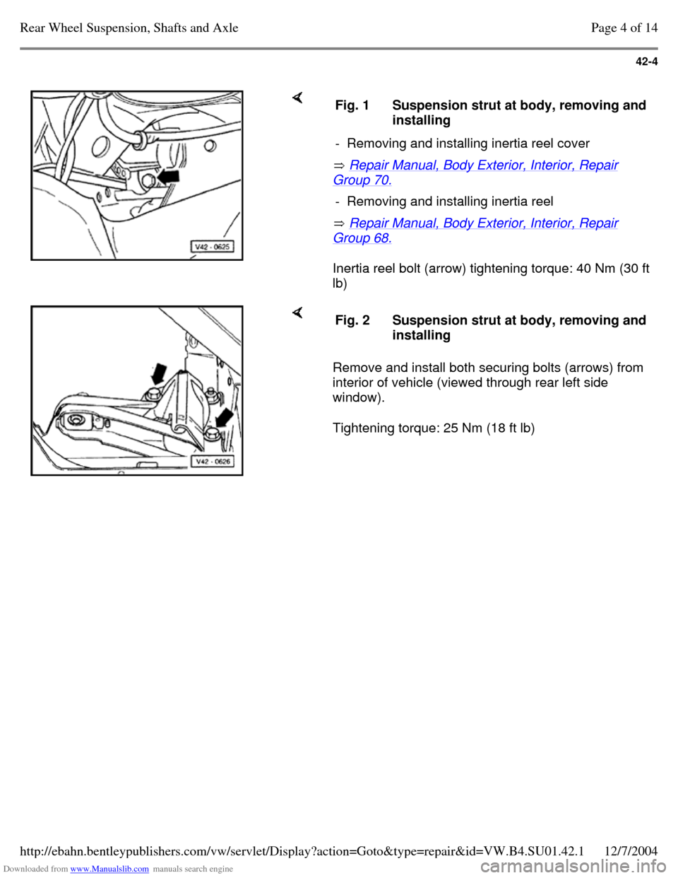
Inertia reel bolt (arrow) tightening torque: 40 Nm (30 ft
lb) Fig. 1 Suspension strut at body, removing and installing
- Removing and installing inertia reel cover - Removing and installing inertia reel Remove and install both securing bolts (arrows) from
interior of vehicle (viewed through rear left side
window).
Tightening torque: 25 Nm (18 ft lb) Fig. 2 Suspension strut at body, removing and installing Page 4 of 14Rear Wheel Suspension, Shafts and Axle12/7/2004http://ebahn.bentleypublishers.com/vw/servlet/Display?action=Goto&type=repair&id=VW.B4.SU01.42.1
Page 104 of 369
Downloaded from www.Manualslib.com manuals search engine 42-8
Reworking cap nut in side member
(front wheel drive vehicles)
If the threads of the cap nut in the side member
are damaged, it must either be retapped or the
cap nut must be drilled out. When drilling out
proceed as follows:
- Remove rear axle.
- Drill through damaged cap nut in the side
member using a 10.2 mm diameter drill from
underneath.
Note:
Do not tilt the drill when drilling.
WARNING!
Wear protective goggles.
- Cut new thread in the cap nut, M 12 x 1.5.
- Use new bolts, Part No. N 010.127.4 (M 12 x 1.5 x 30), and washer, Part No. N 011.531.7, to
secure the rear axle.
Tightening torque: 70 Nm (52 ft lb)
Note:
The procedure described here must only be
performed on one cap nut on each side of the
vehicle. Page 8 of 14Rear Wheel Suspension, Shafts and Axle12/7/2004http://ebahn.bentleypublishers.com/vw/servlet/Display?action=Goto&type=repair&id=VW.B4.SU01.42.1
Page 116 of 369
Downloaded from www.Manualslib.com manuals search engine 42-20
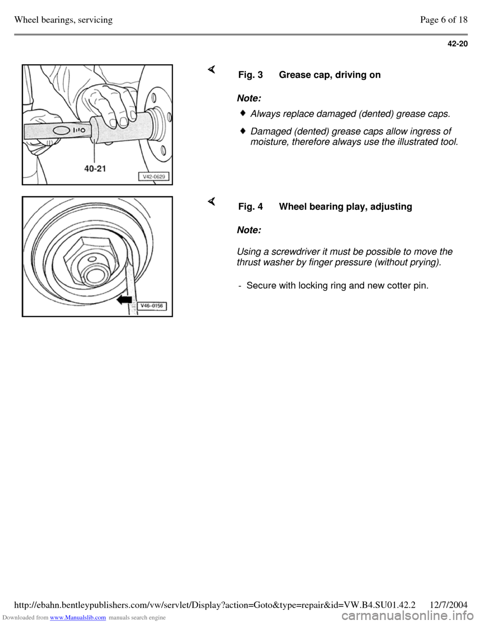
Note: Fig. 3 Grease cap, driving on Always replace damaged (dented) grease caps. Damaged (dented) grease caps allow ingress of
moisture, therefore always use the illustrated tool. Note:
Using a screwdriver it must be possible to move the
thrust washer by finger pressure (without prying). Fig. 4 Wheel bearing play, adjusting - Secure with locking ring and new cotter pin. Page 6 of 18Wheel bearings, servicing12/7/2004http://ebahn.bentleypublishers.com/vw/servlet/Display?action=Goto&type=repair&id=VW.B4.SU01.42.2
Page 126 of 369

Downloaded from www.Manualslib.com manuals search engine 42-30
Note: Fig. 3 Grease cap, driving on Always replace damaged (dented) grease caps. Damaged (dented) grease caps allow ingress of
moisture, therefore always use the illustrated tool. Note:
Using a screwdriver it must be possible to move the
thrust washer by finger pressure (without prying). Fig. 4 Wheel bearing play, adjusting - Secure with locking ring and new cotter pin. Page 16 of 18Wheel bearings, servicing12/7/2004http://ebahn.bentleypublishers.com/vw/servlet/Display?action=Goto&type=repair&id=VW.B4.SU01.42.2
Page 148 of 369
Downloaded from www.Manualslib.com manuals search engine 42-52
- Cut new thread in the cap nut, M 12 x 1.5.
- Use new bolts, Part No. N 010 137.1 and
washer, Part No. N 011 531.7 to secure the rear
axle.
Tightening torque: 65 Nm (48 ft lb)
Note:
The procedure described here must only be
performed on one cap nut on each side of the
vehicle. Page 7 of 7Rear drive shafts, servicing12/7/2004http://ebahn.bentleypublishers.com/vw/servlet/Display?action=Goto&type=repair&id=VW.B4.SU01.42.4
Page 156 of 369
Downloaded from www.Manualslib.com manuals search engine 42-60
Repair Manual, Suspension, Wheels, Brakes, Steering, Repair Group 46
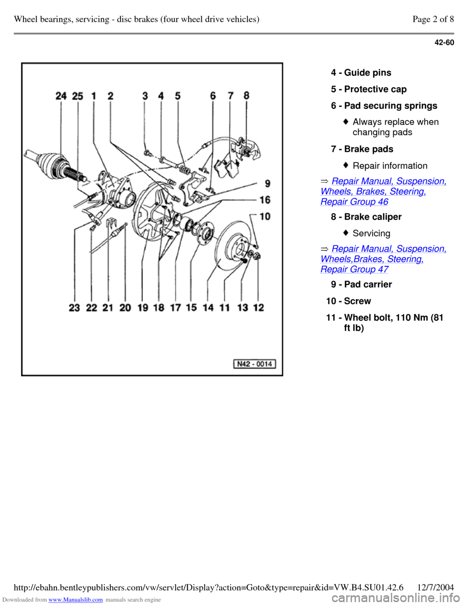
Repair Manual, Suspension, Wheels,Brakes, Steering, Repair Group 47 4 - Guide pins
5 - Protective cap
6 - Pad securing springs Always replace when
changing pads
7 - Brake pads Repair information 8 - Brake caliper Servicing 9 - Pad carrier
10 - Screw
11 - Wheel bolt, 110 Nm (81
ft lb) Page 2 of 8Wheel bearings, servicing - disc brakes (four wheel drive vehicles)12/7/2004http://ebahn.bentleypublishers.com/vw/servlet/Display?action=Goto&type=repair&id=VW.B4.SU01.42.6
Page 173 of 369
Downloaded from www.Manualslib.com manuals search engine 45-4
Control module, removing and installing
Location
Under the rear seat, left
Note:
Switch off ignition before disconnecting and
connecting connectors.
Removing
- Fold up rear seat.
- Press control module securing clips together
and pull out.
- To pull connector off control module, release
control module locking bar.
Installing
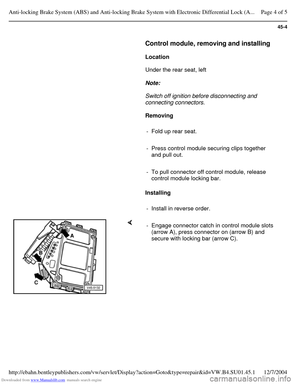
- Install in reverse order. - Engage connector catch in control module slots
(arrow A), press connector on (arrow B) and
secure with locking bar (arrow C). Page 4 of 5Anti-locking Brake System (ABS) and Anti-locking Brake System with Electronic Differential Lock (A...12/7/2004http://ebahn.bentleypublishers.com/vw/servlet/Display?action=Goto&type=repair&id=VW.B4.SU01.45.1
Page 188 of 369
Downloaded from www.Manualslib.com manuals search engine 45-19
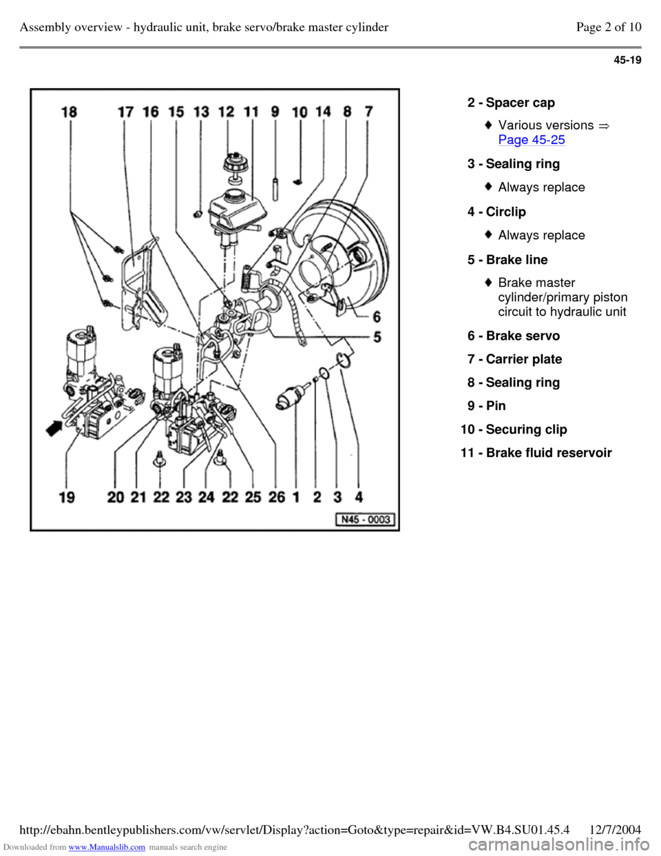
2 - Spacer cap Various versions
Page 45-25 3 - Sealing ring Always replace 4 - Circlip Always replace 5 - Brake line Brake master
cylinder/primary piston
circuit to hydraulic unit
6 - Brake servo
7 - Carrier plate
8 - Sealing ring
9 - Pin
10 - Securing clip
11 - Brake fluid reservoir Page 2 of 10Assembly overview - hydraulic unit, brake servo/brake master cylinder12/7/2004http://ebahn.bentleypublishers.com/vw/servlet/Display?action=Goto&type=repair&id=VW.B4.SU01.45.4