ECU VOLKSWAGEN PASSAT 1996 B3, B4 / 3.G Service Owner's Guide
[x] Cancel search | Manufacturer: VOLKSWAGEN, Model Year: 1996, Model line: PASSAT, Model: VOLKSWAGEN PASSAT 1996 B3, B4 / 3.GPages: 369, PDF Size: 12.33 MB
Page 239 of 369
Downloaded from www.Manualslib.com manuals search engine 46-43
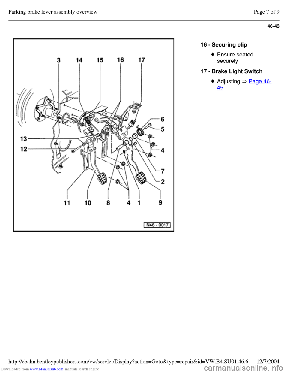
16 - Securing clip Ensure seated
securely
17 - Brake Light Switch Adjusting Page 46-45 Page 7 of 9Parking brake lever assembly overview12/7/2004http://ebahn.bentleypublishers.com/vw/servlet/Display?action=Goto&type=repair&id=VW.B4.SU01.46.6
Page 240 of 369
Downloaded from www.Manualslib.com manuals search engine 46-44
Brake pedal, removing and installing
Note:
Grease all mounting and contact surfaces with
MoS
2 grease.
To remove brake servo disconnect brake pedal
at clevis only.
Removing
- Before removing brake pedal remove trim
- Remove brake pedal clevis pin connection
securing clip.
- Remove pin.
- Remove brake pedal pivot pin securing clip.
- Remove pivot pin.
- Remove mounting sleeve, return spring
mounting tube with brake pedal.
Installing
- Install in reverse order. Page 8 of 9Parking brake lever assembly overview12/7/2004http://ebahn.bentleypublishers.com/vw/servlet/Display?action=Goto&type=repair&id=VW.B4.SU01.46.6
Page 241 of 369
Downloaded from www.Manualslib.com manuals search engine 46-45
Brake Light Switch, adjusting
Note:
The Brake Light Switch must be removed for
adjusting.
- Remove trim under instrument panel.
- Disconnect harness connector for Brake Light
Switch.
- Remove Brake Light Switch by turning to right
through 90.
- Pull Brake Light Switch plunger fully out.
- Depress brake pedal as far as possible by hand,
guide Brake Light Switch through the locating
hole and secure by turning through 90to left.
- Pull brake pedal back up by hand to stop (Brake
Light Switch is pushed back by one notch).
- Connect harness connector for Brake Light
Switch
- Check function of Brake Light Switch.
- Install instrument panel trim. Page 9 of 9Parking brake lever assembly overview12/7/2004http://ebahn.bentleypublishers.com/vw/servlet/Display?action=Goto&type=repair&id=VW.B4.SU01.46.6
Page 280 of 369
Downloaded from www.Manualslib.com manuals search engine 48-10
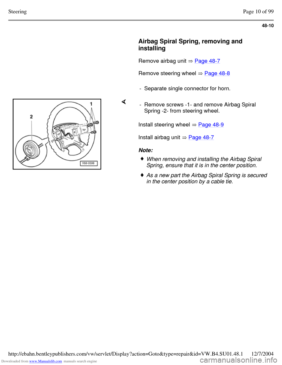
Airbag Spiral Spring, removing and
installing
Remove airbag unit Page 48-7 Remove steering wheel Page 48-8
- Separate single connector for horn. Install steering wheel Page 48-9
Install airbag unit Page 48-7
Note: - Remove screws -1- and remove Airbag Spiral
Spring -2- from steering wheel. When removing and installing the Airbag Spiral
Spring, ensure that it is in the center position. As a new part the Airbag Spiral Spring is secured
in the center position by a cable tie. Page 10 of 99Steering12/7/2004http://ebahn.bentleypublishers.com/vw/servlet/Display?action=Goto&type=repair&id=VW.B4.SU01.48.1
Page 287 of 369
Downloaded from www.Manualslib.com manuals search engine 48-17
Instead of plastic sealing plugs a plug consisting of
Part No.113 301 229 A and banjo bolt, Part No. N
904 674 01 can be used. But when using these,
several 16 mm diameter sealing rings must be used
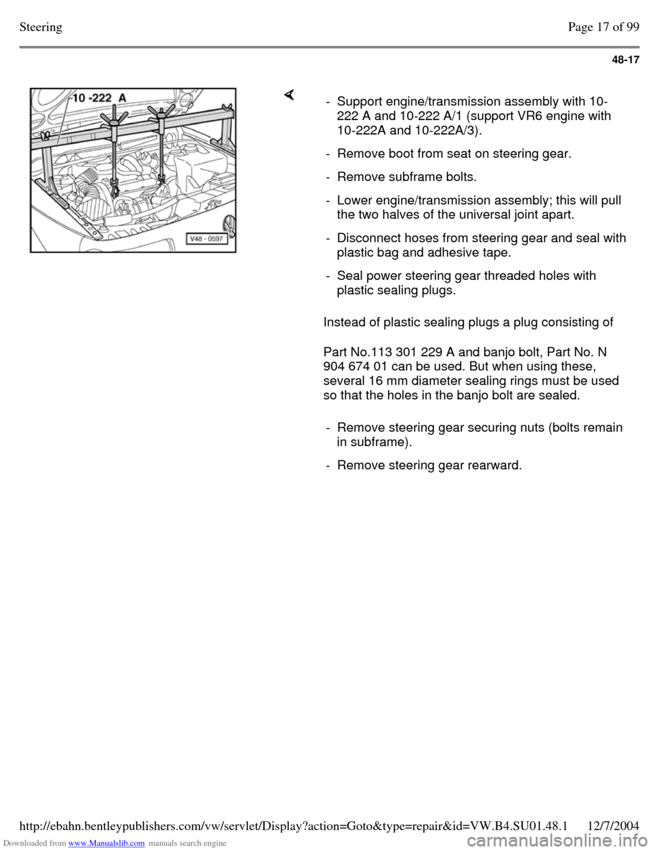
so that the holes in the banjo bolt are sealed. - Support engine/transmission assembly with 10-
222 A and 10-222 A/1 (support VR6 engine with
10-222A and 10-222A/3).
- Remove boot from seat on steering gear. - Remove subframe bolts. - Lower engine/transmission assembly; this will pull
the two halves of the universal joint apart.
- Disconnect hoses from steering gear and seal with plastic bag and adhesive tape.
- Seal power steering gear threaded holes with
plastic sealing plugs.
- Remove steering gear securing nuts (bolts remain
in subframe).
- Remove steering gear rearward. Page 17 of 99Steering12/7/2004http://ebahn.bentleypublishers.com/vw/servlet/Display?action=Goto&type=repair&id=VW.B4.SU01.48.1
Page 347 of 369
Downloaded from www.Manualslib.com manuals search engine 48-77
Tie rods, removing and installing (power
steering gear - TRW and ZF)
Note:
Observe how tie rods are threaded into power
steering gear:
- Tie rods not secured with locking fluid
- Tie rods secured with locking fluid When exchanging secured version tie rods use
locking fluid D6 when installing.
Removing
The tie rods can only be removed/installed with
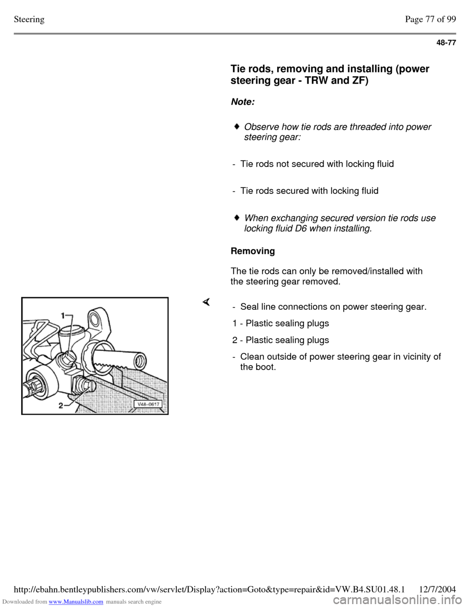
the steering gear removed. - Seal line connections on power steering gear. 1 - Plastic sealing plugs 2 - Plastic sealing plugs - Clean outside of power steering gear in vicinity of
the boot. Page 77 of 99Steering12/7/2004http://ebahn.bentleypublishers.com/vw/servlet/Display?action=Goto&type=repair&id=VW.B4.SU01.48.1
Page 356 of 369
Downloaded from www.Manualslib.com manuals search engine 48-86
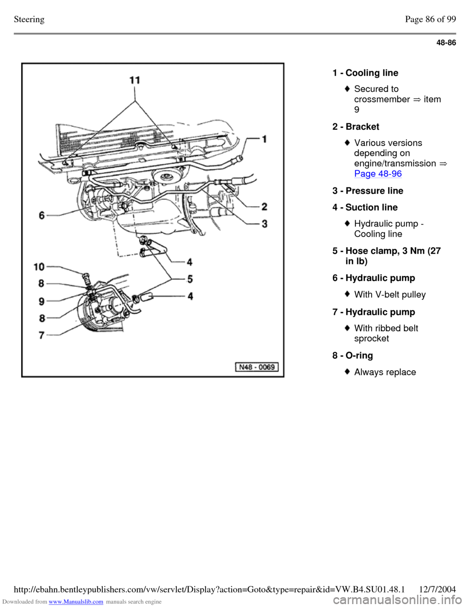
1 - Cooling line Secured to
crossmember item
9 2 - Bracket Various versions
depending on
engine/transmission Page 48-96 3 - Pressure line
4 - Suction line Hydraulic pump -
Cooling line
5 - Hose clamp, 3 Nm (27
in lb)
6 - Hydraulic pump With V-belt pulley 7 - Hydraulic pump With ribbed belt
sprocket
8 - O-ring Always replace Page 86 of 99Steering12/7/2004http://ebahn.bentleypublishers.com/vw/servlet/Display?action=Goto&type=repair&id=VW.B4.SU01.48.1
Page 364 of 369
Downloaded from www.Manualslib.com manuals search engine 48-94
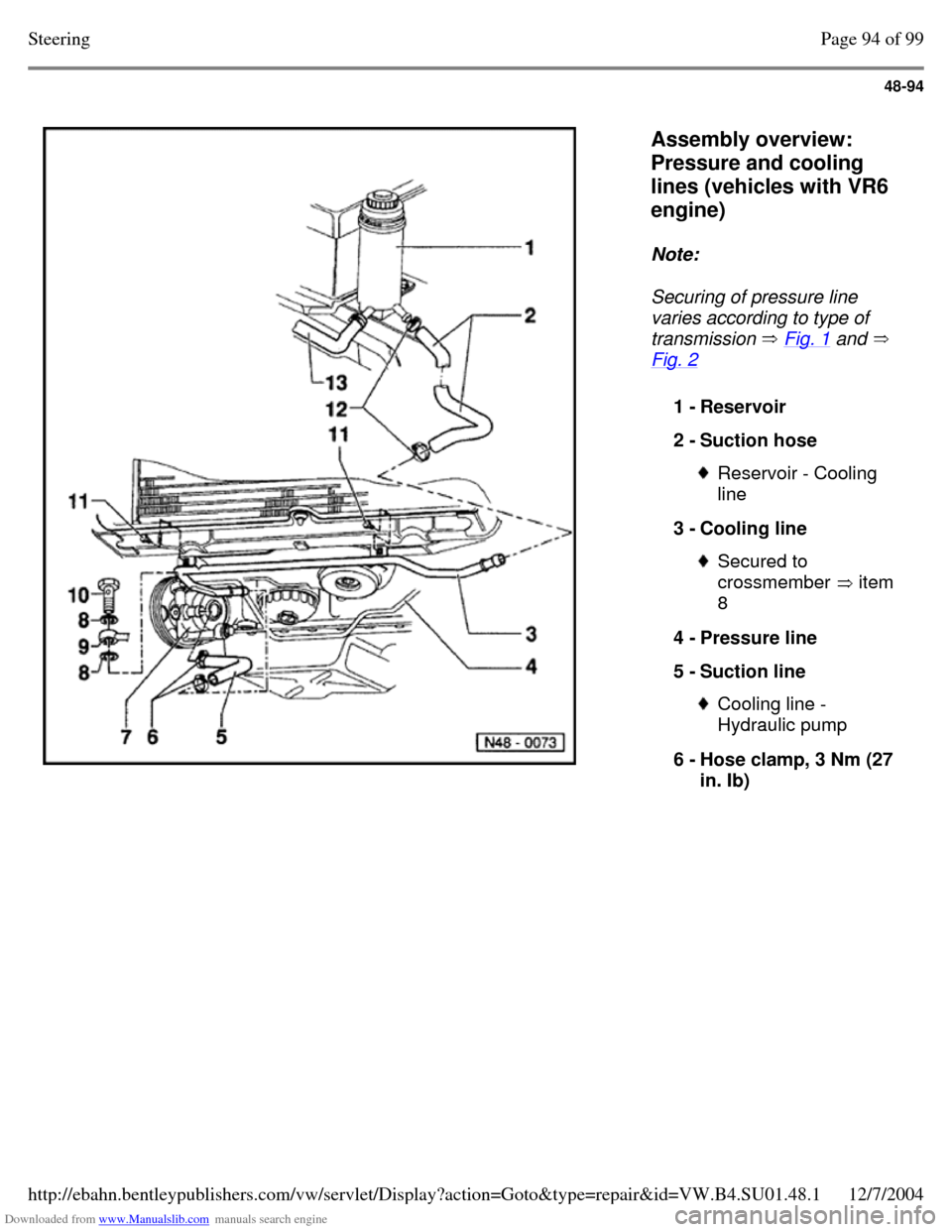
Assembly overview:
Pressure and cooling
lines (vehicles with VR6
engine)
Note:
Securing of pressure line
varies according to type of
transmission Fig. 1 and
Fig. 2 1 - Reservoir
2 - Suction hose Reservoir - Cooling
line
3 - Cooling line Secured to
crossmember item
8 4 - Pressure line
5 - Suction line Cooling line -
Hydraulic pump
6 - Hose clamp, 3 Nm (27
in. Ib) Page 94 of 99Steering12/7/2004http://ebahn.bentleypublishers.com/vw/servlet/Display?action=Goto&type=repair&id=VW.B4.SU01.48.1
Page 366 of 369
Downloaded from www.Manualslib.com manuals search engine 48-96
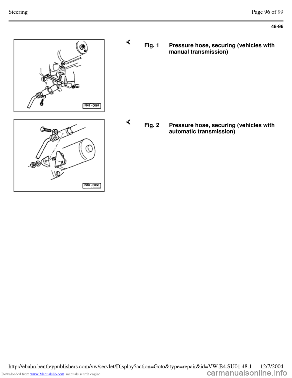
Fig. 1 Pressure hose, securing (vehicles with
manual transmission) Fig. 2 Pressure hose, securing (vehicles with
automatic transmission) Page 96 of 99Steering12/7/2004http://ebahn.bentleypublishers.com/vw/servlet/Display?action=Goto&type=repair&id=VW.B4.SU01.48.1