check engine VOLKSWAGEN PASSAT 1996 B3, B4 / 3.G Service Owner's Manual
[x] Cancel search | Manufacturer: VOLKSWAGEN, Model Year: 1996, Model line: PASSAT, Model: VOLKSWAGEN PASSAT 1996 B3, B4 / 3.GPages: 369, PDF Size: 12.33 MB
Page 80 of 369
Downloaded from www.Manualslib.com manuals search engine 40-66
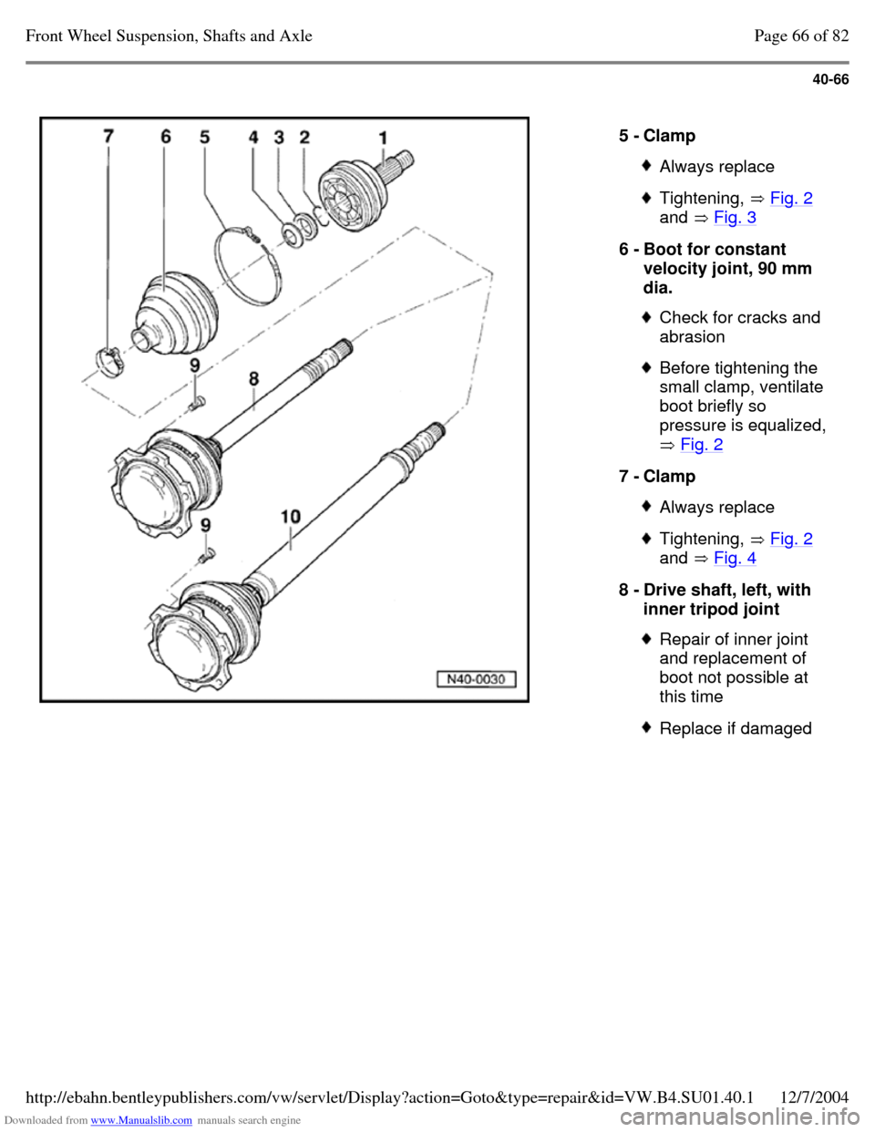
5 - Clamp Always replace Tightening, Fig. 2
and Fig. 3 6 - Boot for constant
velocity joint, 90 mm
dia. Check for cracks and
abrasion Before tightening the
small clamp, ventilate
boot briefly so
pressure is equalized,
Fig. 2 7 - Clamp Always replace Tightening, Fig. 2
and Fig. 4 8 - Drive shaft, left, with
inner tripod joint Repair of inner joint
and replacement of
boot not possible at
this time Replace if damaged Page 66 of 82Front Wheel Suspension, Shafts and Axle12/7/2004http://ebahn.bentleypublishers.com/vw/servlet/Display?action=Goto&type=repair&id=VW.B4.SU01.40.1
Page 87 of 369
Downloaded from www.Manualslib.com manuals search engine 40-73
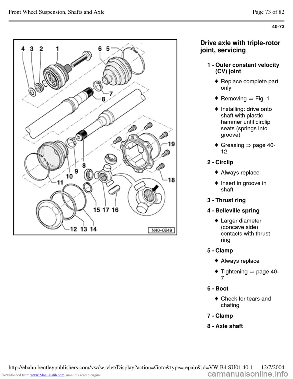
Drive axle with triple-rotor
joint, servicing
1 - Outer constant velocity (CV) joint Replace complete part
only Removing Fig. 1 Installing: drive onto
shaft with plastic
hammer until circlip
seats (springs into
groove) Greasing page 40-
12 2 - Circlip Always replace Insert in groove in
shaft
3 - Thrust ring
4 - Belleville spring Larger diameter
(concave side)
contacts with thrust
ring
5 - Clamp Always replace Tightening page 40-
7 6 - Boot Check for tears and
chafing
7 - Clamp
8 - Axle shaft Page 73 of 82Front Wheel Suspension, Shafts and Axle12/7/2004http://ebahn.bentleypublishers.com/vw/servlet/Display?action=Goto&type=repair&id=VW.B4.SU01.40.1
Page 99 of 369
Downloaded from www.Manualslib.com manuals search engine 42-3
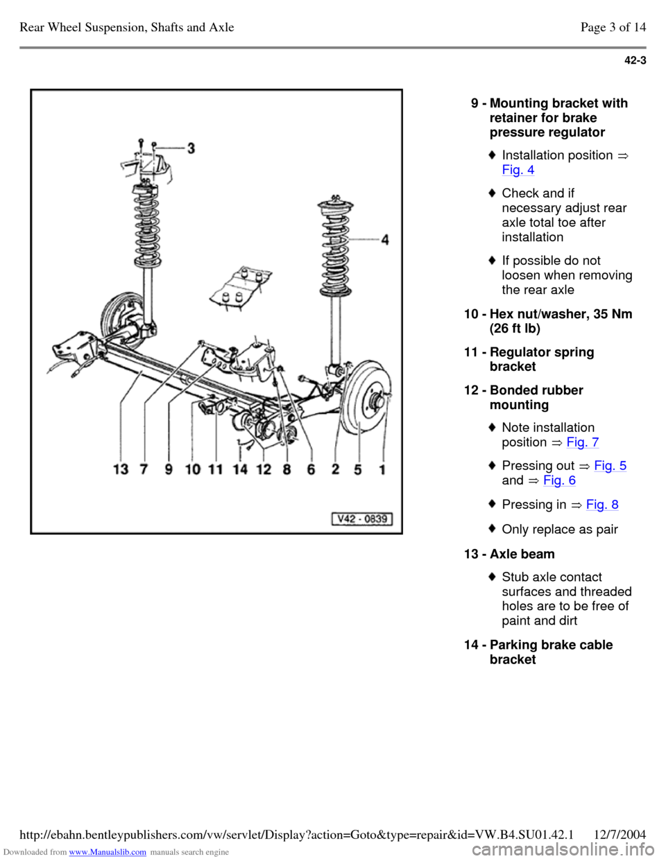
9 - Mounting bracket with
retainer for brake
pressure regulator Installation position
Fig. 4 Check and if
necessary adjust rear
axle total toe after
installation If possible do not
loosen when removing
the rear axle
10 - Hex nut/washer, 35 Nm
(26 ft lb)
11 - Regulator spring
bracket
12 - Bonded rubber
mounting Note installation
position Fig. 7 Pressing out Fig. 5
and Fig. 6 Pressing in Fig. 8 Only replace as pair 13 - Axle beam Stub axle contact
surfaces and threaded
holes are to be free of
paint and dirt
14 - Parking brake cable
bracket Page 3 of 14Rear Wheel Suspension, Shafts and Axle12/7/2004http://ebahn.bentleypublishers.com/vw/servlet/Display?action=Goto&type=repair&id=VW.B4.SU01.42.1
Page 143 of 369
Downloaded from www.Manualslib.com manuals search engine 42-47
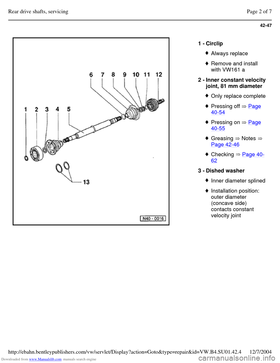
1 - Circlip Always replace Remove and install
with VW161 a
2 - Inner constant velocity
joint, 81 mm diameter Only replace complete Pressing off Page 40-54 Pressing on Page 40-55 Greasing Notes
Page 42-46 Checking Page 40-62 3 - Dished washer Inner diameter splined Installation position:
outer diameter
(concave side)
contacts constant
velocity joint Page 2 of 7Rear drive shafts, servicing12/7/2004http://ebahn.bentleypublishers.com/vw/servlet/Display?action=Goto&type=repair&id=VW.B4.SU01.42.4
Page 144 of 369
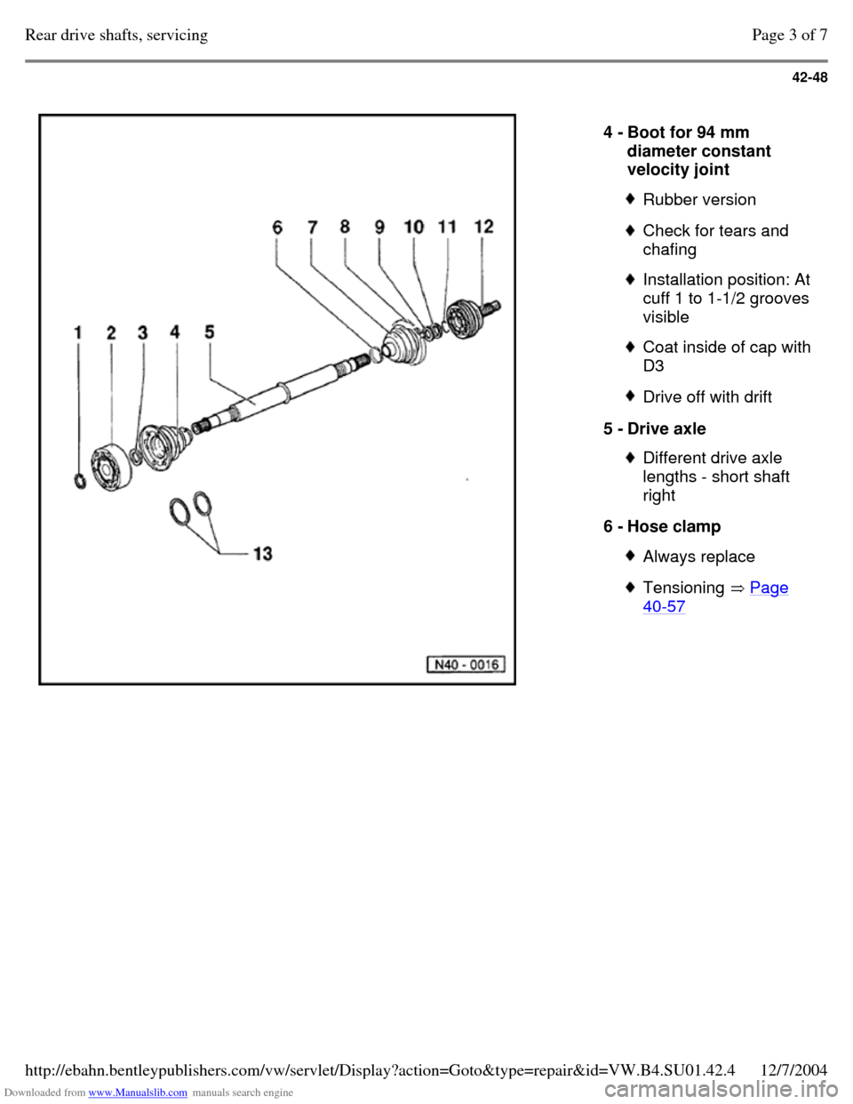
Downloaded from www.Manualslib.com manuals search engine 42-48
4 - Boot for 94 mm
diameter constant
velocity joint Rubber version Check for tears and
chafing Installation position: At
cuff 1 to 1-1/2 grooves
visible Coat inside of cap with D3 Drive off with drift 5 - Drive axle Different drive axle
lengths - short shaft
right
6 - Hose clamp Always replace Tensioning Page 40-57 Page 3 of 7Rear drive shafts, servicing12/7/2004http://ebahn.bentleypublishers.com/vw/servlet/Display?action=Goto&type=repair&id=VW.B4.SU01.42.4
Page 145 of 369
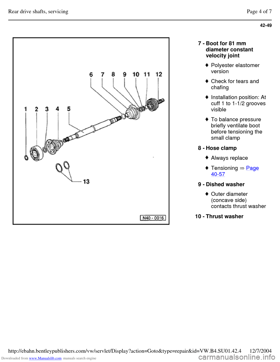
Downloaded from www.Manualslib.com manuals search engine 42-49
7 - Boot for 81 mm
diameter constant
velocity joint Polyester elastomer
version Check for tears and
chafing Installation position: At
cuff 1 to 1-1/2 grooves
visible To balance pressure
briefly ventilate boot
before tensioning the
small clamp
8 - Hose clamp Always replace Tensioning Page 40-57 9 - Dished washer Outer diameter
(concave side)
contacts thrust washer
10 - Thrust washer Page 4 of 7Rear drive shafts, servicing12/7/2004http://ebahn.bentleypublishers.com/vw/servlet/Display?action=Goto&type=repair&id=VW.B4.SU01.42.4
Page 146 of 369
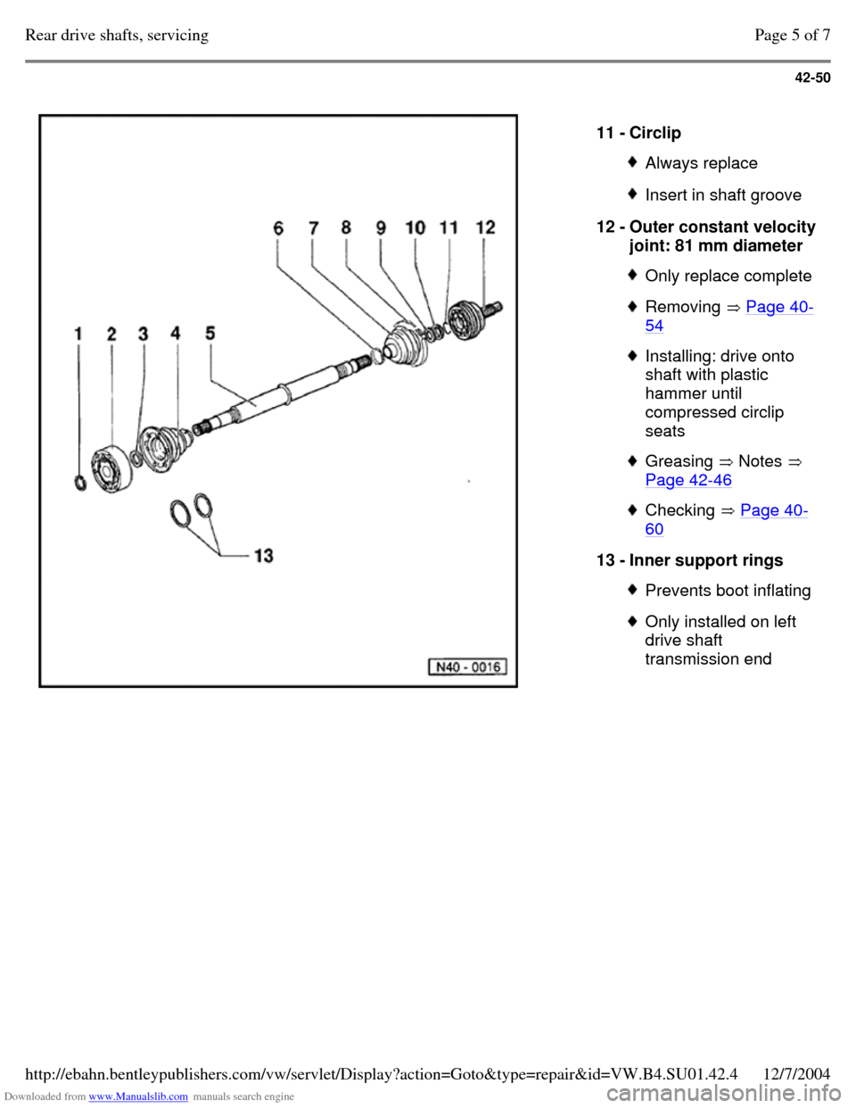
Downloaded from www.Manualslib.com manuals search engine 42-50
11 - Circlip Always replace Insert in shaft groove 12 - Outer constant velocity joint: 81 mm diameter Only replace complete Removing Page 40-54 Installing: drive onto
shaft with plastic
hammer until
compressed circlip
seats Greasing Notes
Page 42-46 Checking Page 40-60 13 - Inner support rings Prevents boot inflating Only installed on left
drive shaft
transmission end Page 5 of 7Rear drive shafts, servicing12/7/2004http://ebahn.bentleypublishers.com/vw/servlet/Display?action=Goto&type=repair&id=VW.B4.SU01.42.4
Page 151 of 369
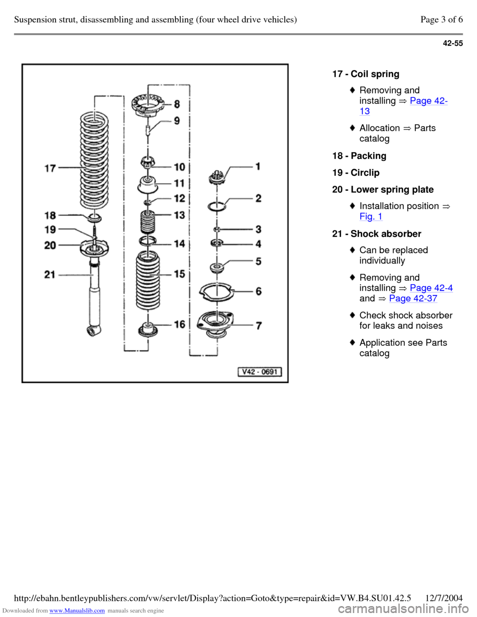
Downloaded from www.Manualslib.com manuals search engine 42-55
17 - Coil spring Removing and
installing Page 42-13 Allocation Parts
catalog 18 - Packing
19 - Circlip
20 - Lower spring plate Installation position
Fig. 1 21 - Shock absorber Can be replaced
individually Removing and
installing Page 42-4
and Page 42-37 Check shock absorber
for leaks and noises Application see Parts
catalog Page 3 of 6Suspension strut, disassembling and assembling (four wheel drive vehicles)12/7/2004http://ebahn.bentleypublishers.com/vw/servlet/Display?action=Goto&type=repair&id=VW.B4.SU01.42.5
Page 163 of 369
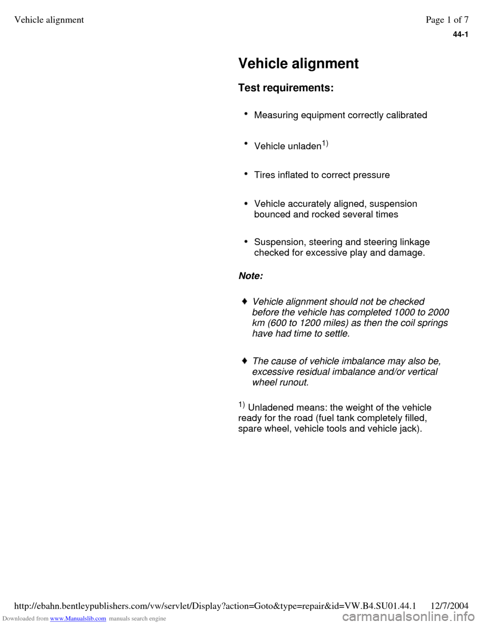
Downloaded from www.Manualslib.com manuals search engine 44-1
Vehicle alignment
Test requirements:
Measuring equipment correctly calibrated
Vehicle unladen1)
Tires inflated to correct pressure
Vehicle accurately aligned, suspension
bounced and rocked several times
Suspension, steering and steering linkage
checked for excessive play and damage.
Note:
Vehicle alignment should not be checked
before the vehicle has completed 1000 to 2000
km (600 to 1200 miles) as then the coil springs
have had time to settle.
The cause of vehicle imbalance may also be,
excessive residual imbalance and/or vertical
wheel runout.
1)
Unladened means: the weight of the vehicle
ready for the road (fuel tank completely filled,
spare wheel, vehicle tools and vehicle jack). Page 1 of 7Vehicle alignment12/7/2004http://ebahn.bentleypublishers.com/vw/servlet/Display?action=Goto&type=repair&id=VW.B4.SU01.44.1
Page 164 of 369
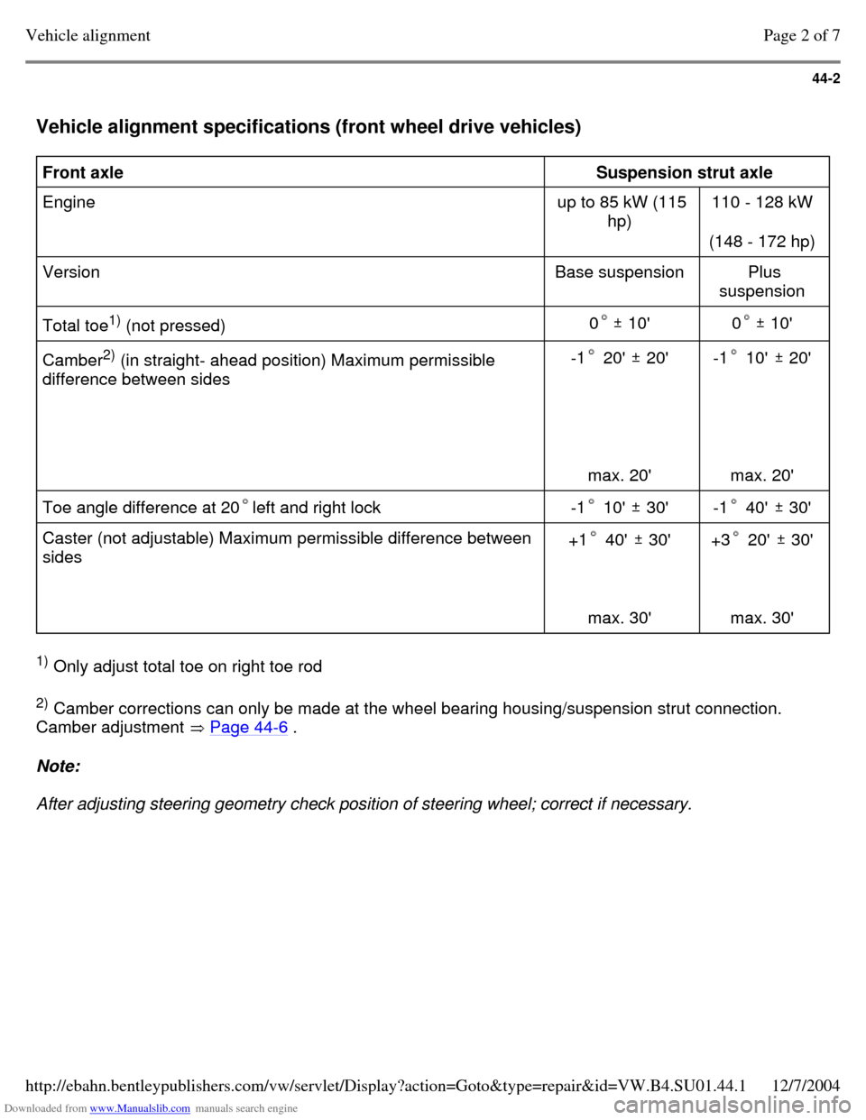
Downloaded from www.Manualslib.com manuals search engine 44-2
Vehicle alignment specifications (front wheel drive vehicles) Front axle
Suspension strut axle
Engine up to 85 kW (115
hp) 110 - 128 kW
(148 - 172 hp)
Version Base suspension Plus
suspension
Total toe1)
(not pressed)
0 10' 0 10' Camber2)
(in straight- ahead position) Maximum permissible
difference between sides -1 20' 20'
max. 20' -1 10' 20'
max. 20' Toe angle difference at 20left and right lock -1 10' 30' -1 40' 30' Caster (not adjustable) Maximum permissible difference between
sides +1 40' 30'
max. 30' +3 20' 30'
max. 30' 1)
Only adjust total toe on right toe rod
2)
Camber corrections can only be made at the wheel bearing housing/suspension strut connection.
Camber adjustment Page 44-6 . Note:
After adjusting steering geometry check position of steering wheel; correct if necessary. Page 2 of 7Vehicle alignment12/7/2004http://ebahn.bentleypublishers.com/vw/servlet/Display?action=Goto&type=repair&id=VW.B4.SU01.44.1