check engine VOLKSWAGEN PASSAT 1996 B3, B4 / 3.G Service Owner's Guide
[x] Cancel search | Manufacturer: VOLKSWAGEN, Model Year: 1996, Model line: PASSAT, Model: VOLKSWAGEN PASSAT 1996 B3, B4 / 3.GPages: 369, PDF Size: 12.33 MB
Page 166 of 369
Downloaded from www.Manualslib.com manuals search engine 44-4
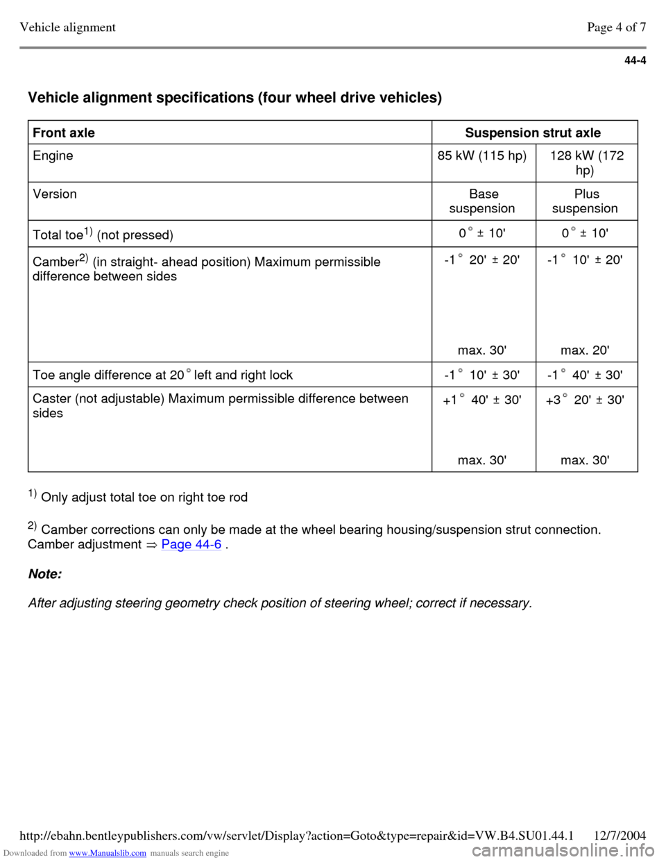
Vehicle alignment specifications (four wheel drive vehicles) Front axle
Suspension strut axle
Engine 85 kW (115 hp) 128 kW (172
hp)
Version Base
suspension Plus
suspension
Total toe1)
(not pressed)
0 10' 0 10' Camber2)
(in straight- ahead position) Maximum permissible
difference between sides -1 20' 20'
max. 30' -1 10' 20'
max. 20' Toe angle difference at 20left and right lock -1 10' 30' -1 40' 30' Caster (not adjustable) Maximum permissible difference between
sides +1 40' 30'
max. 30' +3 20' 30'
max. 30' 1)
Only adjust total toe on right toe rod
2)
Camber corrections can only be made at the wheel bearing housing/suspension strut connection.
Camber adjustment Page 44-6 . Note:
After adjusting steering geometry check position of steering wheel; correct if necessary. Page 4 of 7Vehicle alignment12/7/2004http://ebahn.bentleypublishers.com/vw/servlet/Display?action=Goto&type=repair&id=VW.B4.SU01.44.1
Page 168 of 369
Downloaded from www.Manualslib.com manuals search engine 44-6
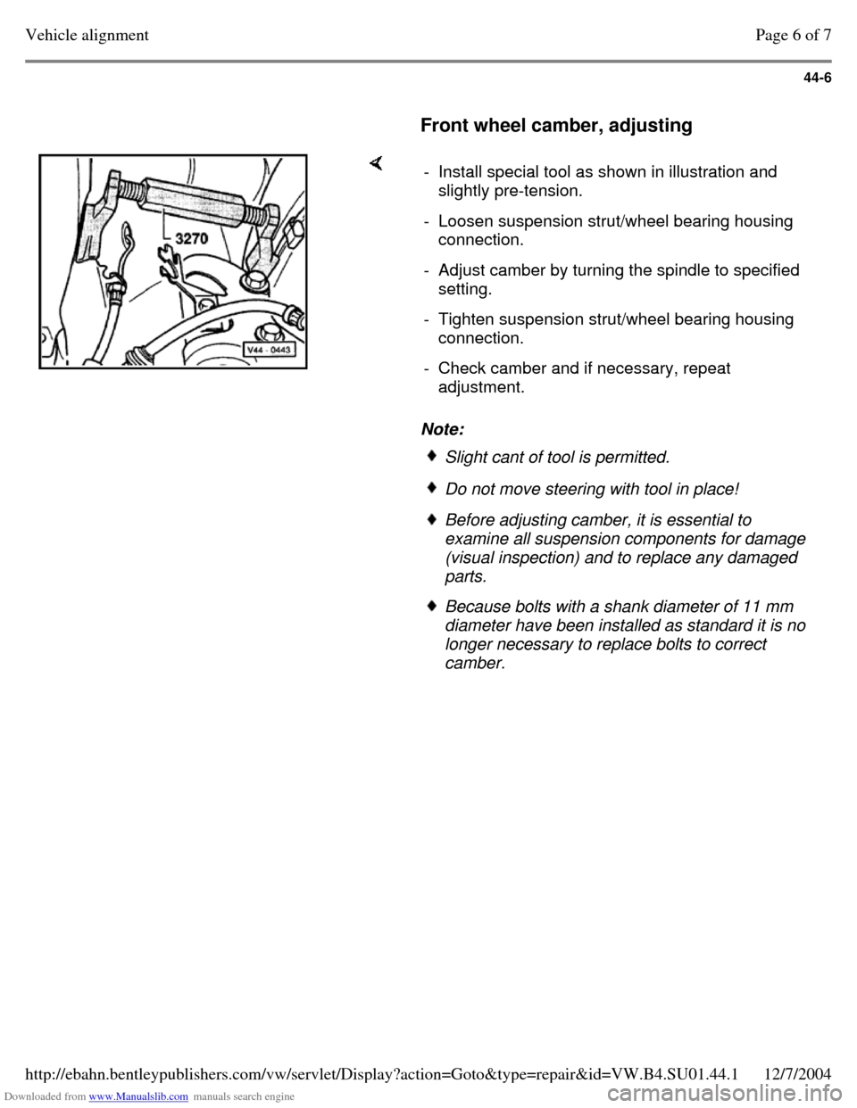
Front wheel camber, adjusting Note: - Install special tool as shown in illustration and
slightly pre-tension.
- Loosen suspension strut/wheel bearing housing
connection.
- Adjust camber by turning the spindle to specified
setting.
- Tighten suspension strut/wheel bearing housing
connection.
- Check camber and if necessary, repeat
adjustment. Slight cant of tool is permitted. Do not move steering with tool in place! Before adjusting camber, it is essential to
examine all suspension components for damage
(visual inspection) and to replace any damaged
parts. Because bolts with a shank diameter of 11 mm
diameter have been installed as standard it is no
longer necessary to replace bolts to correct
camber. Page 6 of 7Vehicle alignment12/7/2004http://ebahn.bentleypublishers.com/vw/servlet/Display?action=Goto&type=repair&id=VW.B4.SU01.44.1
Page 174 of 369
Downloaded from www.Manualslib.com manuals search engine 45-5
Wheel speed sensor and rotor for speed
sensor, removing and installing
Speed sensor
When installing speed sensor ensure wiring is
not twisted.
Before installing speed sensor, clean mounting
hole and coat with lubricating paste, G 000 650.
Rotors
Before installing check that rotor is clean and
undamaged.
Front axle
Vehicles with base suspension Page 40-14 . Vehicles with plus suspension Page 40-23 .
Rear axle
Vehicles with rear drum brakes Page 42-15 . Vehicles with rear disc brakes (front and four
wheel drive Page 42-24 . Page 5 of 5Anti-locking Brake System (ABS) and Anti-locking Brake System with Electronic Differential Lock (A...12/7/2004http://ebahn.bentleypublishers.com/vw/servlet/Display?action=Goto&type=repair&id=VW.B4.SU01.45.1
Page 180 of 369
Downloaded from www.Manualslib.com manuals search engine 45-11
ABS hydraulic unit and ABS control
module (Teves 20 GI), removing and
installing
Carefully read and follow all cautions and
warnings Page 45-7 before beginning work.
Location
The ABS control module is bolted to the ABS
hydraulic unit, located on the left-side of the
engine compartment.
CAUTION!
Do not bend brake lines at or near the ABS
hydraulic unit.
Switch ignition OFF when disconnecting and
reconnecting the ABS control module
connector.
Part numbers are listed here for reference
only. Always check with your Parts
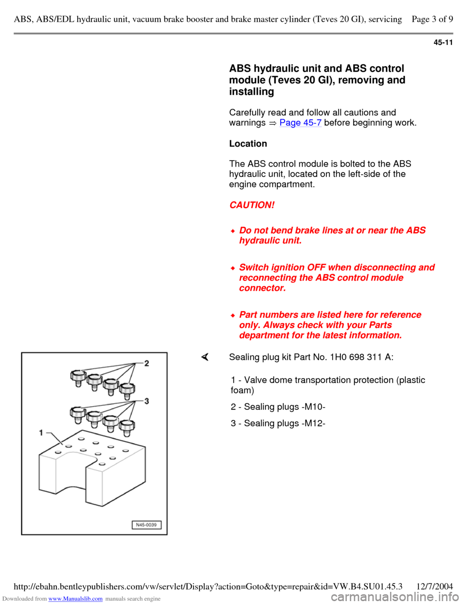
department for the latest information. Sealing plug kit Part No. 1H0 698 311 A:
1 - Valve dome transportation protection (plastic
foam)
2 - Sealing plugs -M10- 3 - Sealing plugs -M12- Page 3 of 9ABS, ABS/EDL hydraulic unit, vacuum brake booster and brake master cylinder (Teves 20 GI), servicing12/7/2004http://ebahn.bentleypublishers.com/vw/servlet/Display?action=Goto&type=repair&id=VW.B4.SU01.45.3
Page 187 of 369
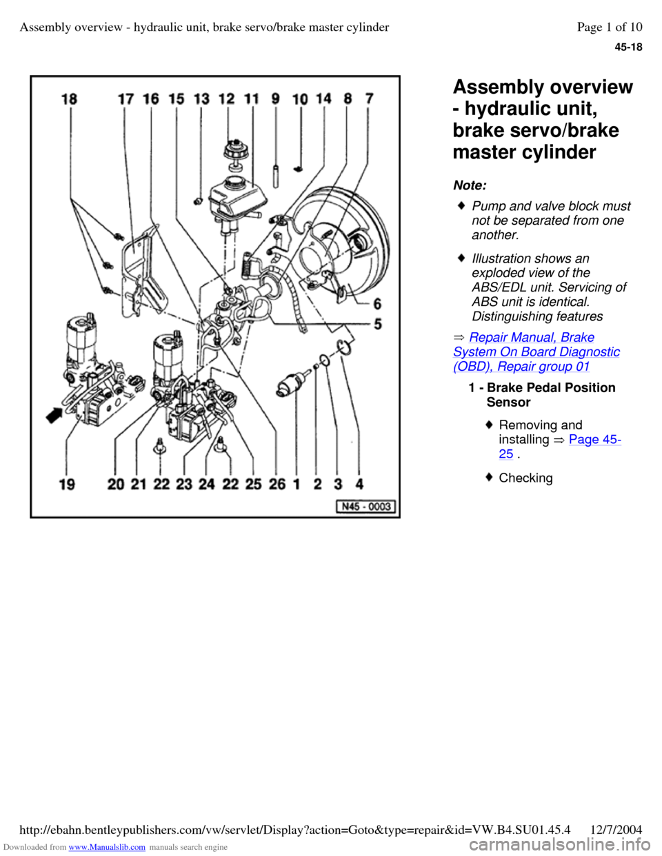
Downloaded from www.Manualslib.com manuals search engine 45-18
Assembly overview
- hydraulic unit,
brake servo/brake
master cylinder
Note:
Repair Manual, Brake System On Board Diagnostic (OBD), Repair group 01 Pump and valve block must
not be separated from one
another. Illustration shows an
exploded view of the
ABS/EDL unit. Servicing of
ABS unit is identical.
Distinguishing features 1 - Brake Pedal Position
Sensor Removing and
installing Page 45-25 . Checking Page 1 of 10Assembly overview - hydraulic unit, brake servo/brake master cylinder12/7/2004http://ebahn.bentleypublishers.com/vw/servlet/Display?action=Goto&type=repair&id=VW.B4.SU01.45.4
Page 189 of 369
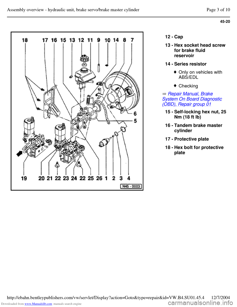
Downloaded from www.Manualslib.com manuals search engine 45-20
Repair Manual, Brake System On Board Diagnostic (OBD), Repair group 01 12 - Cap
13 - Hex socket head screw for brake fluid
reservoir
14 - Series resistor Only on vehicles with
ABS/EDL Checking 15 - Self-locking hex nut, 25 Nm (18 ft lb)
16 - Tandem brake master
cylinder
17 - Protective plate
18 - Hex bolt for protective
plate Page 3 of 10Assembly overview - hydraulic unit, brake servo/brake master cylinder12/7/2004http://ebahn.bentleypublishers.com/vw/servlet/Display?action=Goto&type=repair&id=VW.B4.SU01.45.4
Page 199 of 369
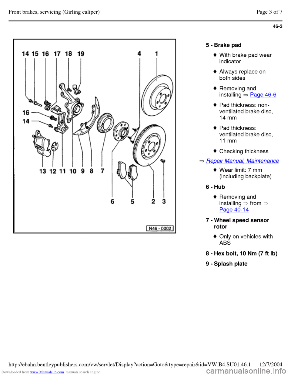
Downloaded from www.Manualslib.com manuals search engine 46-3
Repair Manual, Maintenance 5 - Brake pad With brake pad wear
indicator Always replace on
both sides Removing and
installing Page 46-6 Pad thickness: non-
ventilated brake disc,
14 mm Pad thickness:
ventilated brake disc,
11 mm Checking thickness Wear limit: 7 mm
(including backplate)
6 - Hub Removing and
installing from
Page 40-14 7 - Wheel speed sensor
rotor Only on vehicles with
ABS
8 - Hex bolt, 10 Nm (7 ft lb) 9 - Splash plate Page 3 of 7Front brakes, servicing (Girling caliper)12/7/2004http://ebahn.bentleypublishers.com/vw/servlet/Display?action=Goto&type=repair&id=VW.B4.SU01.46.1
Page 204 of 369
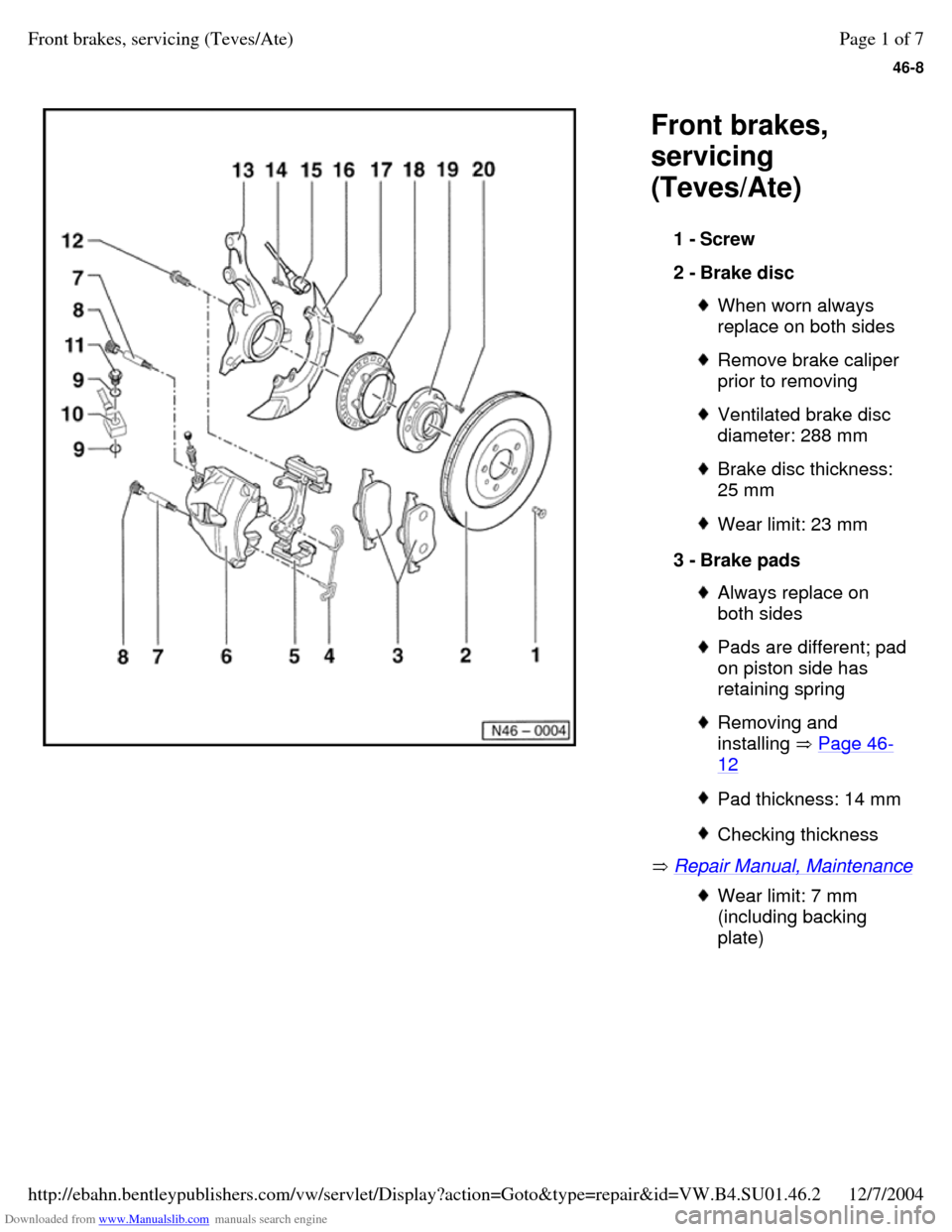
Downloaded from www.Manualslib.com manuals search engine 46-8
Front brakes,
servicing
(Teves/Ate)
Repair Manual, Maintenance 1 - Screw
2 - Brake disc When worn always
replace on both sides Remove brake caliper
prior to removing Ventilated brake disc
diameter: 288 mm Brake disc thickness:
25 mm Wear limit: 23 mm 3 - Brake pads Always replace on
both sides Pads are different; pad on piston side has
retaining spring Removing and
installing Page 46-12 Pad thickness: 14 mm Checking thickness Wear limit: 7 mm
(including backing
plate) Page 1 of 7Front brakes, servicing (Teves/Ate)12/7/2004http://ebahn.bentleypublishers.com/vw/servlet/Display?action=Goto&type=repair&id=VW.B4.SU01.46.2
Page 212 of 369
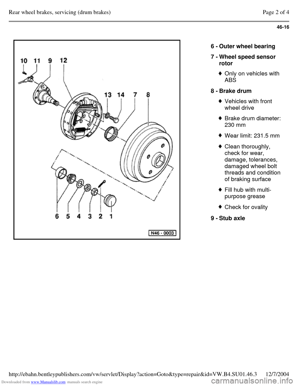
Downloaded from www.Manualslib.com manuals search engine 46-16
6 - Outer wheel bearing
7 - Wheel speed sensor
rotor Only on vehicles with
ABS
8 - Brake drum Vehicles with front
wheel drive Brake drum diameter:
230 mm Wear limit: 231.5 mm Clean thoroughly,
check for wear,
damage, tolerances,
damaged wheel bolt
threads and condition
of braking surface Fill hub with multi-
purpose grease Check for ovality 9 - Stub axle Page 2 of 4Rear wheel brakes, servicing (drum brakes)12/7/2004http://ebahn.bentleypublishers.com/vw/servlet/Display?action=Goto&type=repair&id=VW.B4.SU01.46.3
Page 216 of 369
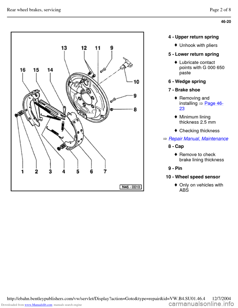
Downloaded from www.Manualslib.com manuals search engine 46-20
Repair Manual, Maintenance 4 - Upper return spring Unhook with pliers 5 - Lower return spring Lubricate contact
points with G 000 650
paste
6 - Wedge spring
7 - Brake shoe Removing and
installing Page 46-23 Minimum lining
thickness 2.5 mm Checking thickness 8 - Cap Remove to check
brake lining thickness
9 - Pin
10 - Wheel speed sensor Only on vehicles with
ABS Page 2 of 8Rear wheel brakes, servicing12/7/2004http://ebahn.bentleypublishers.com/vw/servlet/Display?action=Goto&type=repair&id=VW.B4.SU01.46.4