boot VOLKSWAGEN PASSAT 1997 B3, B4 / 3.G Service User Guide
[x] Cancel search | Manufacturer: VOLKSWAGEN, Model Year: 1997, Model line: PASSAT, Model: VOLKSWAGEN PASSAT 1997 B3, B4 / 3.GPages: 369, PDF Size: 12.33 MB
Page 72 of 369
Downloaded from www.Manualslib.com manuals search engine 40-58
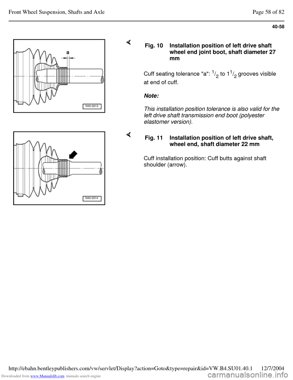
Cuff seating tolerance "a": 1
/
2 to 11
/
2 grooves visible
at end of cuff.
Note:
This installation position tolerance is also valid for the
left drive shaft transmission end boot (polyester
elastomer version). Fig. 10 Installation position of left drive shaft
wheel end joint boot, shaft diameter 27
mm Cuff installation position: Cuff butts against shaft
shoulder (arrow). Fig. 11 Installation position of left drive shaft,
wheel end, shaft diameter 22 mm Page 58 of 82Front Wheel Suspension, Shafts and Axle12/7/2004http://ebahn.bentleypublishers.com/vw/servlet/Display?action=Goto&type=repair&id=VW.B4.SU01.40.1
Page 73 of 369
Downloaded from www.Manualslib.com manuals search engine 40-59
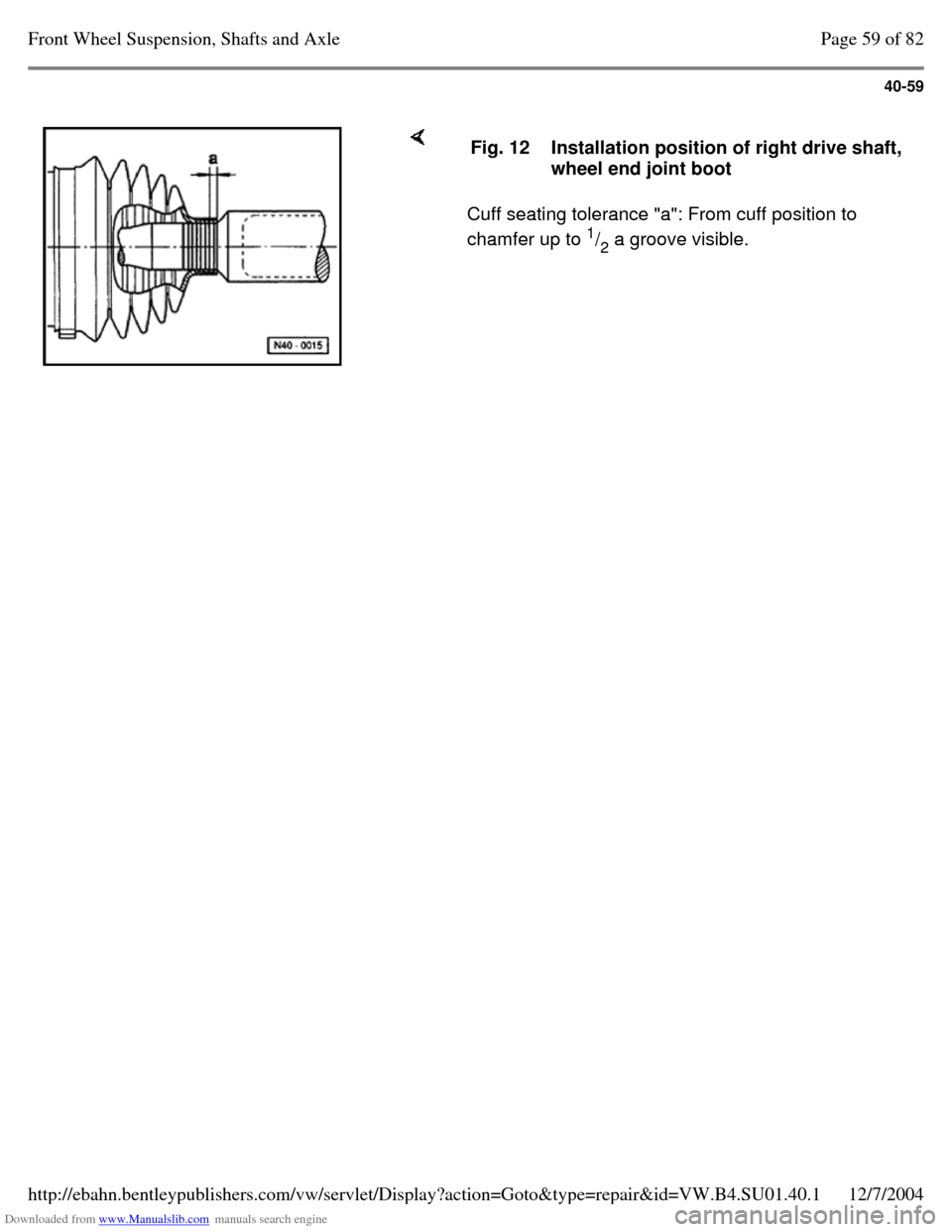
Cuff seating tolerance "a": From cuff position to
chamfer up to 1
/
2 a groove visible. Fig. 12 Installation position of right drive shaft,
wheel end joint boot Page 59 of 82Front Wheel Suspension, Shafts and Axle12/7/2004http://ebahn.bentleypublishers.com/vw/servlet/Display?action=Goto&type=repair&id=VW.B4.SU01.40.1
Page 75 of 369
Downloaded from www.Manualslib.com manuals search engine 40-61
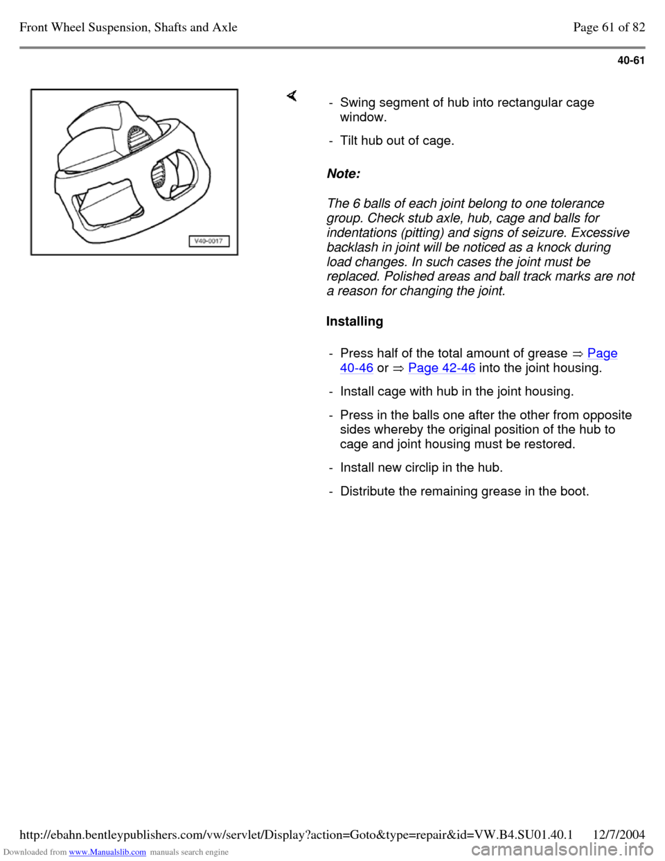
Note:
The 6 balls of each joint belong to one tolerance
group. Check stub axle, hub, cage and balls for
indentations (pitting) and signs of seizure. Excessive
backlash in joint will be noticed as a knock during
load changes. In such cases the joint must be
replaced. Polished areas and ball track marks are not
a reason for changing the joint.
Installing - Swing segment of hub into rectangular cage
window.
- Tilt hub out of cage. - Press half of the total amount of grease Page 40-46 or Page 42-46 into the joint housing. - Install cage with hub in the joint housing. - Press in the balls one after the other from opposite sides whereby the original position of the hub to
cage and joint housing must be restored.
- Install new circlip in the hub. - Distribute the remaining grease in the boot. Page 61 of 82Front Wheel Suspension, Shafts and Axle12/7/2004http://ebahn.bentleypublishers.com/vw/servlet/Display?action=Goto&type=repair&id=VW.B4.SU01.40.1
Page 80 of 369
Downloaded from www.Manualslib.com manuals search engine 40-66
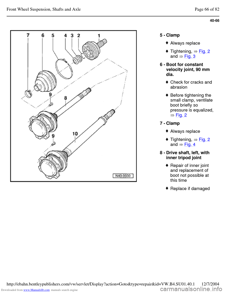
5 - Clamp Always replace Tightening, Fig. 2
and Fig. 3 6 - Boot for constant
velocity joint, 90 mm
dia. Check for cracks and
abrasion Before tightening the
small clamp, ventilate
boot briefly so
pressure is equalized,
Fig. 2 7 - Clamp Always replace Tightening, Fig. 2
and Fig. 4 8 - Drive shaft, left, with
inner tripod joint Repair of inner joint
and replacement of
boot not possible at
this time Replace if damaged Page 66 of 82Front Wheel Suspension, Shafts and Axle12/7/2004http://ebahn.bentleypublishers.com/vw/servlet/Display?action=Goto&type=repair&id=VW.B4.SU01.40.1
Page 81 of 369
Downloaded from www.Manualslib.com manuals search engine 40-67
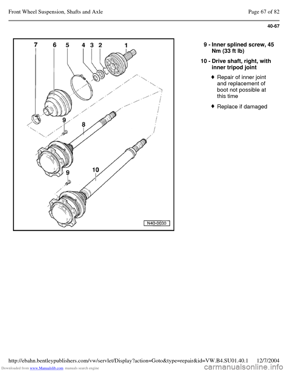
9 - Inner splined screw, 45 Nm (33 ft lb)
10 - Drive shaft, right, with
inner tripod joint Repair of inner joint
and replacement of
boot not possible at
this time Replace if damaged Page 67 of 82Front Wheel Suspension, Shafts and Axle12/7/2004http://ebahn.bentleypublishers.com/vw/servlet/Display?action=Goto&type=repair&id=VW.B4.SU01.40.1
Page 82 of 369
Downloaded from www.Manualslib.com manuals search engine 40-68
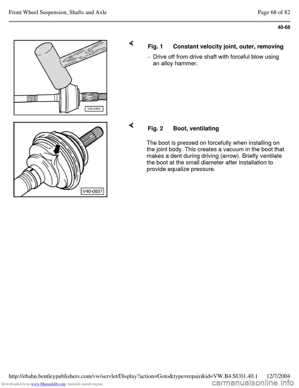
Fig. 1 Constant velocity joint, outer, removing - Drive off from drive shaft with forceful blow using
an alloy hammer. The boot is pressed on forcefully when installing on
the joint body. This creates a vacuum in the boot that
makes a dent during driving (arrow). Briefly ventilate
the boot at the small diameter after installation to
provide equalize pressure. Fig. 2 Boot, ventilating Page 68 of 82Front Wheel Suspension, Shafts and Axle12/7/2004http://ebahn.bentleypublishers.com/vw/servlet/Display?action=Goto&type=repair&id=VW.B4.SU01.40.1
Page 83 of 369
Downloaded from www.Manualslib.com manuals search engine 40-69
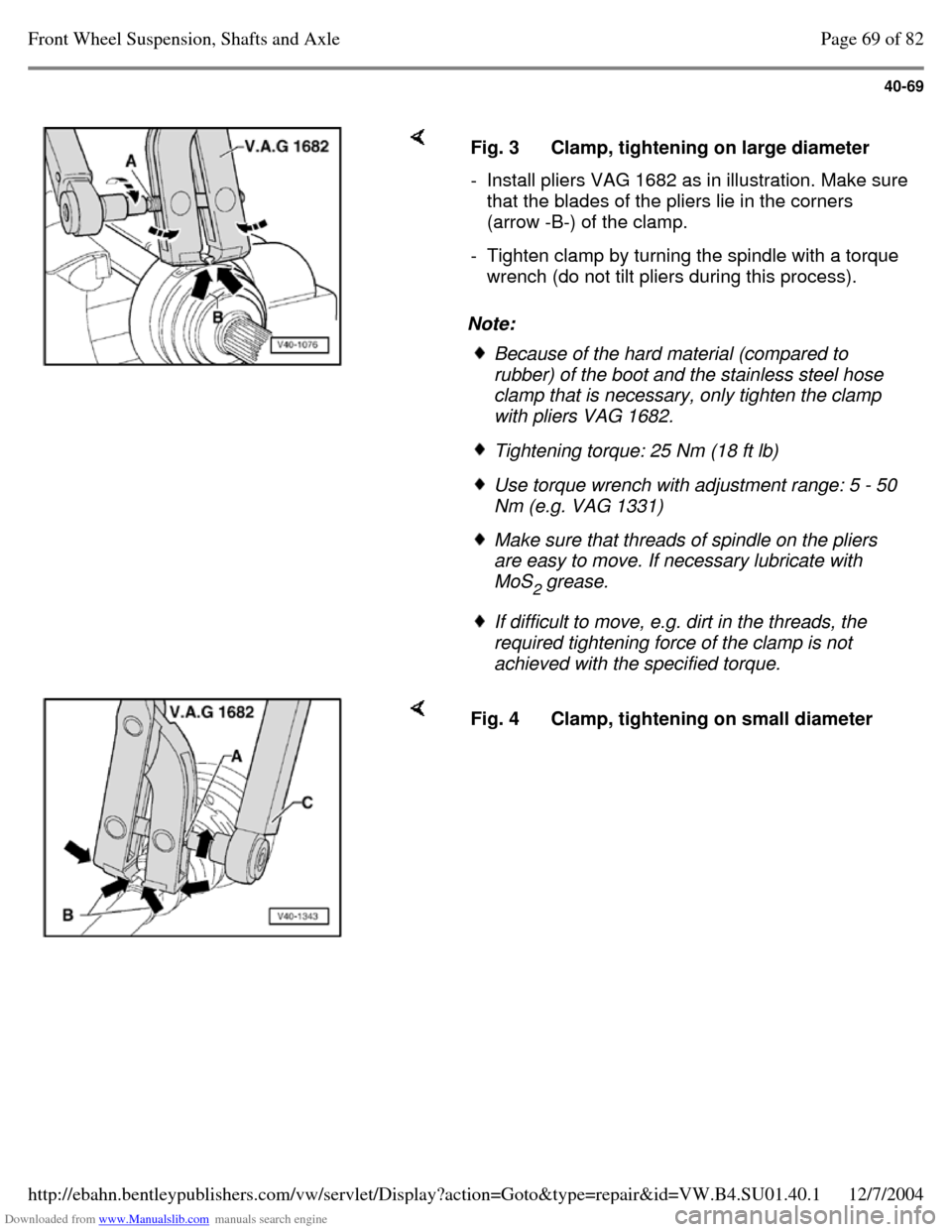
Note: Fig. 3 Clamp, tightening on large diameter - Install pliers VAG 1682 as in illustration. Make sure that the blades of the pliers lie in the corners
(arrow -B-) of the clamp.
- Tighten clamp by turning the spindle with a torque
wrench (do not tilt pliers during this process). Because of the hard material (compared to
rubber) of the boot and the stainless steel hose
clamp that is necessary, only tighten the clamp
with pliers VAG 1682. Tightening torque: 25 Nm (18 ft lb) Use torque wrench with adjustment range: 5 - 50
Nm (e.g. VAG 1331) Make sure that threads of spindle on the pliers
are easy to move. If necessary lubricate with
MoS
2 grease. If difficult to move, e.g. dirt in the threads, the
required tightening force of the clamp is not
achieved with the specified torque. Fig. 4 Clamp, tightening on small diameter Page 69 of 82Front Wheel Suspension, Shafts and Axle12/7/2004http://ebahn.bentleypublishers.com/vw/servlet/Display?action=Goto&type=repair&id=VW.B4.SU01.40.1
Page 87 of 369
Downloaded from www.Manualslib.com manuals search engine 40-73
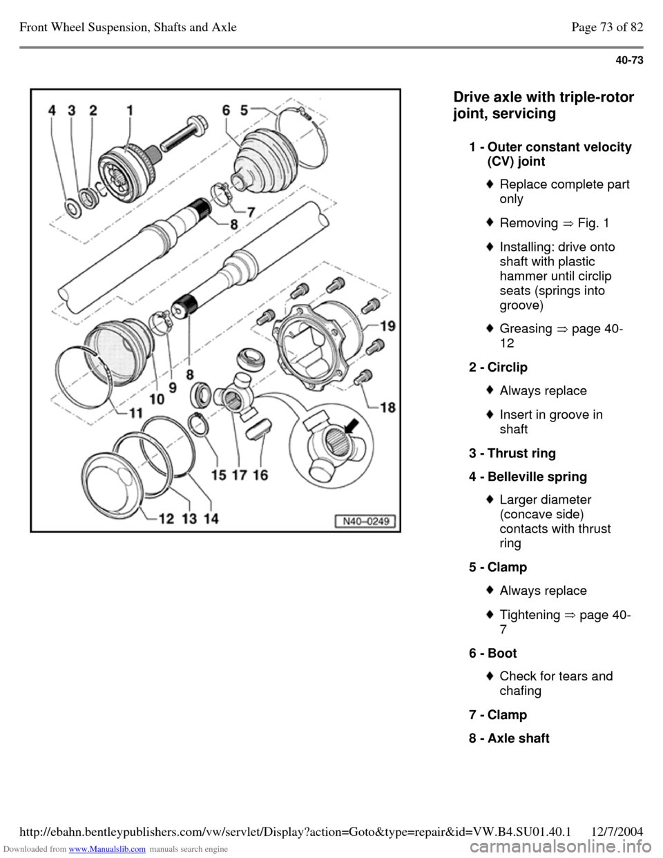
Drive axle with triple-rotor
joint, servicing
1 - Outer constant velocity (CV) joint Replace complete part
only Removing Fig. 1 Installing: drive onto
shaft with plastic
hammer until circlip
seats (springs into
groove) Greasing page 40-
12 2 - Circlip Always replace Insert in groove in
shaft
3 - Thrust ring
4 - Belleville spring Larger diameter
(concave side)
contacts with thrust
ring
5 - Clamp Always replace Tightening page 40-
7 6 - Boot Check for tears and
chafing
7 - Clamp
8 - Axle shaft Page 73 of 82Front Wheel Suspension, Shafts and Axle12/7/2004http://ebahn.bentleypublishers.com/vw/servlet/Display?action=Goto&type=repair&id=VW.B4.SU01.40.1
Page 88 of 369
Downloaded from www.Manualslib.com manuals search engine 40-74
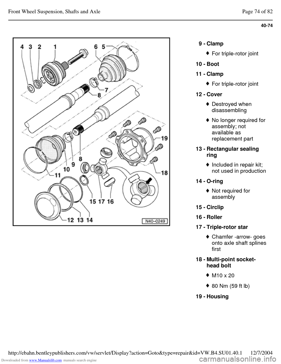
9 - Clamp For triple-rotor joint 10 - Boot
11 - Clamp For triple-rotor joint 12 - Cover Destroyed when
disassembling No longer required for
assembly; not
available as
replacement part
13 - Rectangular sealing
ring Included in repair kit;
not used in production
14 - O-ring Not required for
assembly
15 - Circlip
16 - Roller
17 - Triple-rotor star Chamfer -arrow- goes
onto axle shaft splines
first
18 - Multi-point socket-
head bolt M10 x 20 80 Nm (59 ft lb) 19 - Housing Page 74 of 82Front Wheel Suspension, Shafts and Axle12/7/2004http://ebahn.bentleypublishers.com/vw/servlet/Display?action=Goto&type=repair&id=VW.B4.SU01.40.1
Page 90 of 369
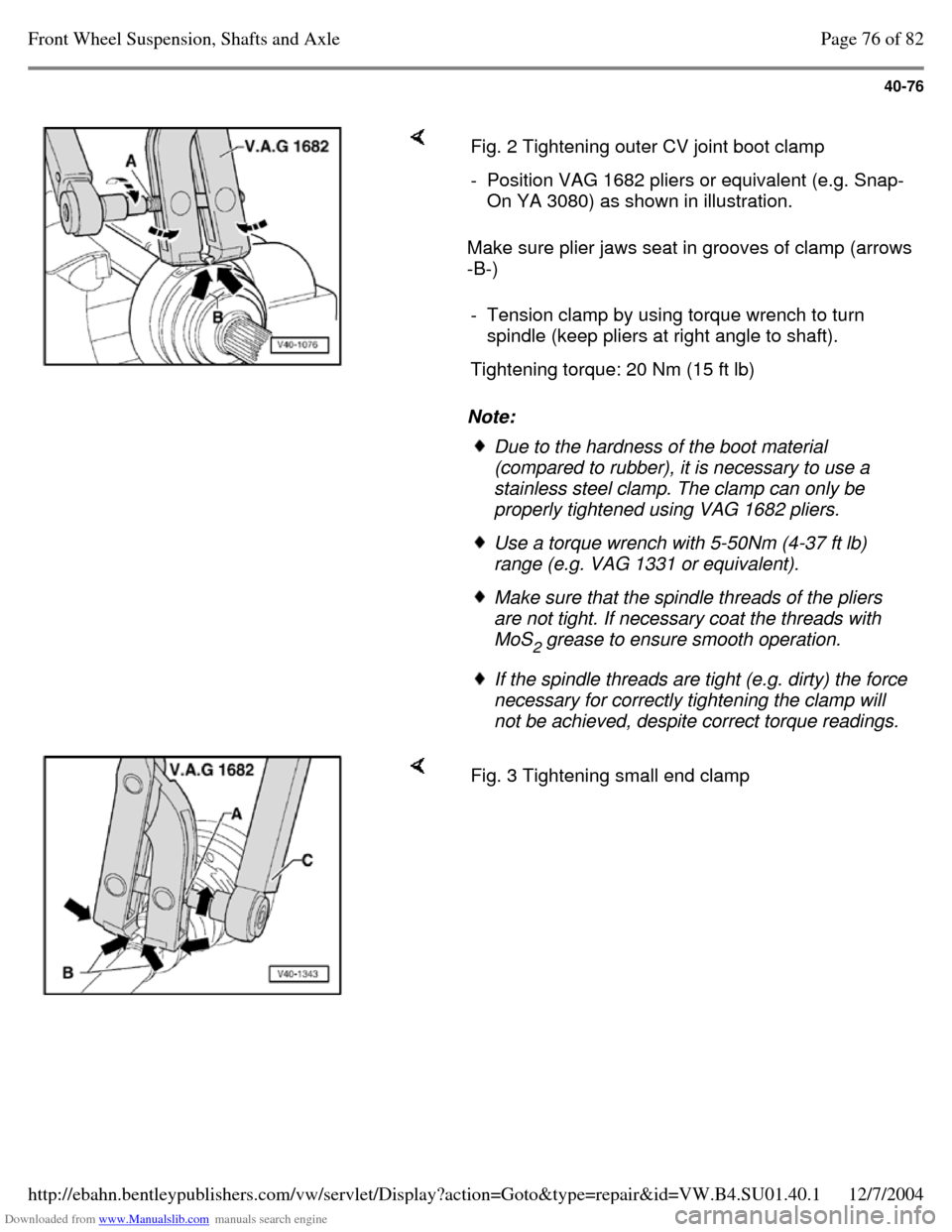
Downloaded from www.Manualslib.com manuals search engine 40-76
Make sure plier jaws seat in grooves of clamp (arrows
-B-)
Note: Fig. 2 Tightening outer CV joint boot clamp - Position VAG 1682 pliers or equivalent (e.g. Snap-
On YA 3080) as shown in illustration.
- Tension clamp by using torque wrench to turn
spindle (keep pliers at right angle to shaft).
Tightening torque: 20 Nm (15 ft lb) Due to the hardness of the boot material
(compared to rubber), it is necessary to use a
stainless steel clamp. The clamp can only be
properly tightened using VAG 1682 pliers. Use a torque wrench with 5-50Nm (4-37 ft lb)
range (e.g. VAG 1331 or equivalent). Make sure that the spindle threads of the pliers
are not tight. If necessary coat the threads with
MoS
2 grease to ensure smooth operation. If the spindle threads are tight (e.g. dirty) the force
necessary for correctly tightening the clamp will
not be achieved, despite correct torque readings. Fig. 3 Tightening small end clamp Page 76 of 82Front Wheel Suspension, Shafts and Axle12/7/2004http://ebahn.bentleypublishers.com/vw/servlet/Display?action=Goto&type=repair&id=VW.B4.SU01.40.1