display VOLKSWAGEN PASSAT 1997 B3, B4 / 3.G Service Workshop Manual
[x] Cancel search | Manufacturer: VOLKSWAGEN, Model Year: 1997, Model line: PASSAT, Model: VOLKSWAGEN PASSAT 1997 B3, B4 / 3.GPages: 369, PDF Size: 12.33 MB
Page 339 of 369
Downloaded from www.Manualslib.com manuals search engine 48-69
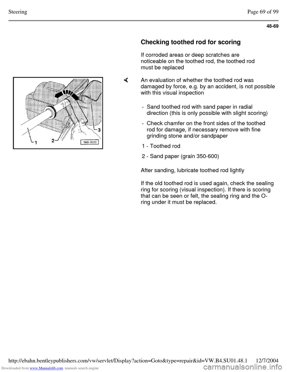
Checking toothed rod for scoring
If corroded areas or deep scratches are
noticeable on the toothed rod, the toothed rod
must be replaced An evaluation of whether the toothed rod was
damaged by force, e.g. by an accident, is not possible
with this visual inspection
After sanding, lubricate toothed rod lightly
If the old toothed rod is used again, check the sealing
ring for scoring (visual inspection). If there is scoring
that can be seen or felt, the sealing ring and the O-
ring under it must be replaced. - Sand toothed rod with sand paper in radial
direction (this is only possible with slight scoring)
- Check chamfer on the front sides of the toothed
rod for damage, if necessary remove with fine
grinding stone and/or sandpaper
1 - Toothed rod 2 - Sand paper (grain 350-600) Page 69 of 99Steering12/7/2004http://ebahn.bentleypublishers.com/vw/servlet/Display?action=Goto&type=repair&id=VW.B4.SU01.48.1
Page 340 of 369
Downloaded from www.Manualslib.com manuals search engine 48-70
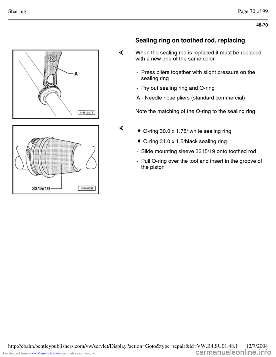
Sealing ring on toothed rod, replacing When the sealing rod is replaced it must be replaced
with a new one of the same color
Note the matching of the O-ring to the sealing ring - Press pliers together with slight pressure on the
sealing ring
- Pry out sealing ring and O-ring A - Needle nose pliers (standard commercial) O-ring 30.0 x 1.78/ white sealing ring O-ring 31.0 x 1.5/black sealing ring - Slide mounting sleeve 3315/19 onto toothed rod - Pull O-ring over the tool and insert in the groove of
the piston Page 70 of 99Steering12/7/2004http://ebahn.bentleypublishers.com/vw/servlet/Display?action=Goto&type=repair&id=VW.B4.SU01.48.1
Page 341 of 369
Downloaded from www.Manualslib.com manuals search engine 48-71
Power steering gear, assembling
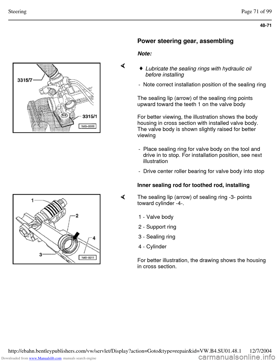
Note: The sealing lip (arrow) of the sealing ring points
upward toward the teeth 1 on the valve body
For better viewing, the illustration shows the body
housing in cross section with installed valve body.
The valve body is shown slightly raised for better
viewing
Inner sealing rod for toothed rod, installing Lubricate the sealing rings with hydraulic oil
before installing
- Note correct installation position of the sealing ring - Place sealing ring for valve body on the tool and
drive in to stop. For installation position, see next
illustration
- Drive center roller bearing for valve body into stop The sealing lip (arrow) of sealing ring -3- points
toward cylinder -4-.
For better illustration, the drawing shows the housing
in cross section. 1 - Valve body 2 - Support ring 3 - Sealing ring 4 - Cylinder Page 71 of 99Steering12/7/2004http://ebahn.bentleypublishers.com/vw/servlet/Display?action=Goto&type=repair&id=VW.B4.SU01.48.1
Page 342 of 369
Downloaded from www.Manualslib.com manuals search engine 48-72
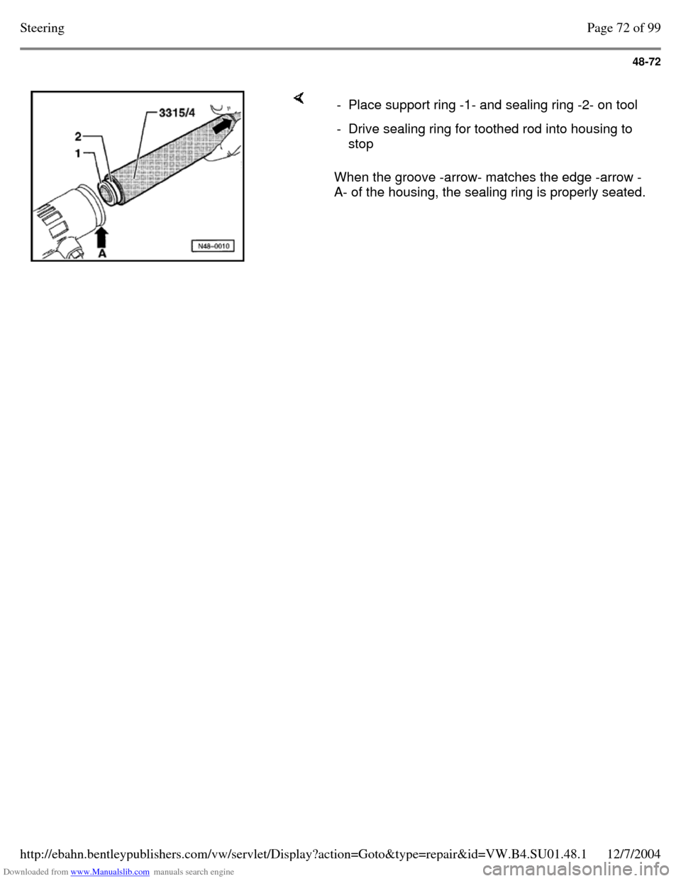
When the groove -arrow- matches the edge -arrow -
A- of the housing, the sealing ring is properly seated. - Place support ring -1- and sealing ring -2- on tool - Drive sealing ring for toothed rod into housing to
stop Page 72 of 99Steering12/7/2004http://ebahn.bentleypublishers.com/vw/servlet/Display?action=Goto&type=repair&id=VW.B4.SU01.48.1
Page 343 of 369
Downloaded from www.Manualslib.com manuals search engine 48-73
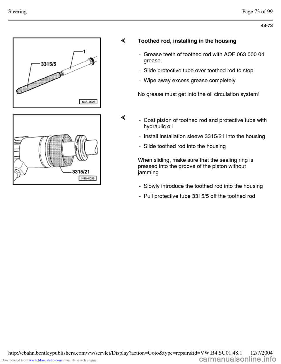
Toothed rod, installing in the housing
No grease must get into the oil circulation system! - Grease teeth of toothed rod with AOF 063 000 04
grease
- Slide protective tube over toothed rod to stop - Wipe away excess grease completely When sliding, make sure that the sealing ring is
pressed into the groove of the piston without
jamming - Coat piston of toothed rod and protective tube with
hydraulic oil
- Install installation sleeve 3315/21 into the housing - Slide toothed rod into the housing - Slowly introduce the toothed rod into the housing - Pull protective tube 3315/5 off the toothed rod Page 73 of 99Steering12/7/2004http://ebahn.bentleypublishers.com/vw/servlet/Display?action=Goto&type=repair&id=VW.B4.SU01.48.1
Page 345 of 369
Downloaded from www.Manualslib.com manuals search engine 48-75
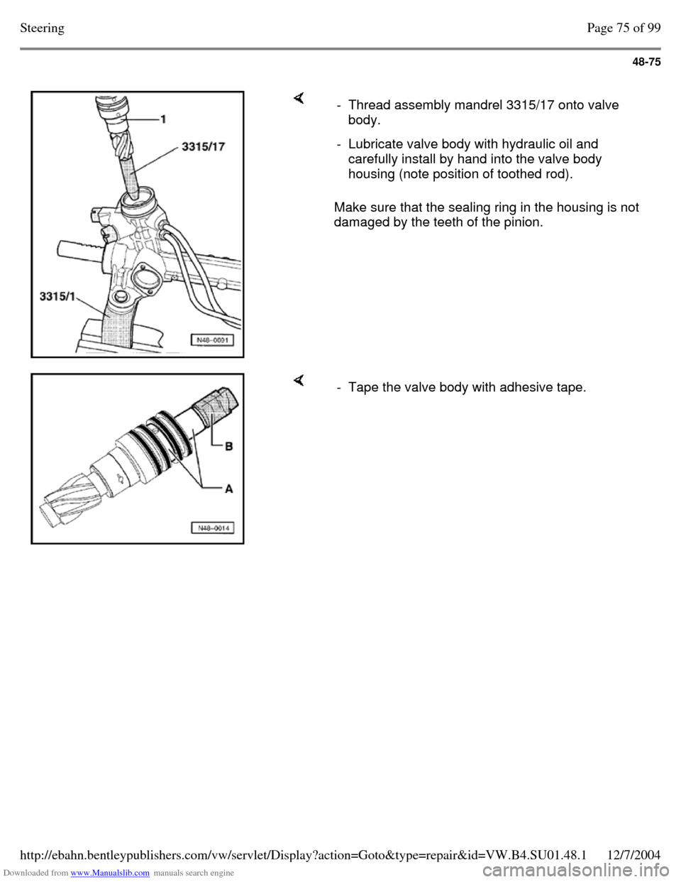
Make sure that the sealing ring in the housing is not
damaged by the teeth of the pinion. - Thread assembly mandrel 3315/17 onto valve
body.
- Lubricate valve body with hydraulic oil and
carefully install by hand into the valve body
housing (note position of toothed rod). - Tape the valve body with adhesive tape. Page 75 of 99Steering12/7/2004http://ebahn.bentleypublishers.com/vw/servlet/Display?action=Goto&type=repair&id=VW.B4.SU01.48.1
Page 346 of 369
Downloaded from www.Manualslib.com manuals search engine 48-76
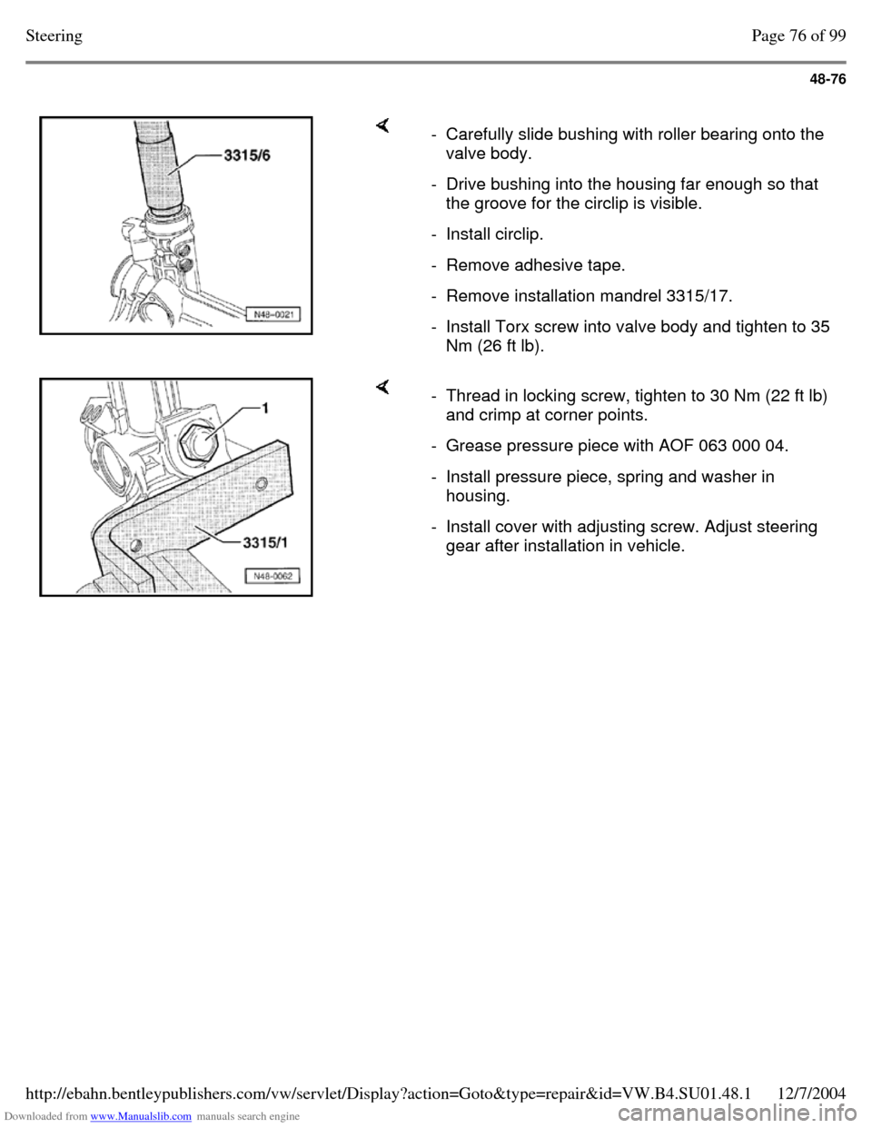
- Carefully slide bushing with roller bearing onto the
valve body.
- Drive bushing into the housing far enough so that
the groove for the circlip is visible.
- Install circlip. - Remove adhesive tape. - Remove installation mandrel 3315/17. - Install Torx screw into valve body and tighten to 35 Nm (26 ft lb). - Thread in locking screw, tighten to 30 Nm (22 ft lb)
and crimp at corner points.
- Grease pressure piece with AOF 063 000 04. - Install pressure piece, spring and washer in
housing.
- Install cover with adjusting screw. Adjust steering
gear after installation in vehicle. Page 76 of 99Steering12/7/2004http://ebahn.bentleypublishers.com/vw/servlet/Display?action=Goto&type=repair&id=VW.B4.SU01.48.1
Page 347 of 369
Downloaded from www.Manualslib.com manuals search engine 48-77
Tie rods, removing and installing (power
steering gear - TRW and ZF)
Note:
Observe how tie rods are threaded into power
steering gear:
- Tie rods not secured with locking fluid
- Tie rods secured with locking fluid When exchanging secured version tie rods use
locking fluid D6 when installing.
Removing
The tie rods can only be removed/installed with
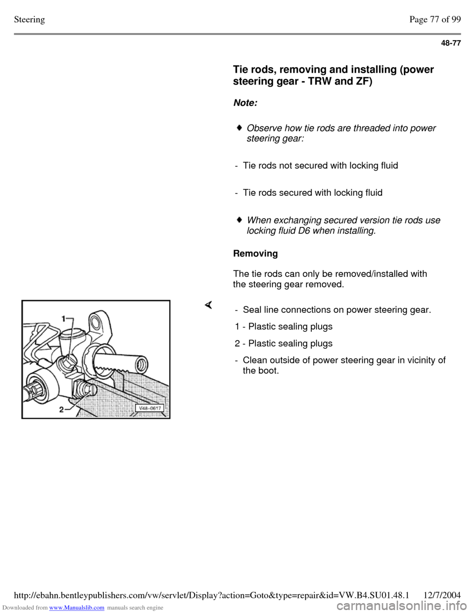
the steering gear removed. - Seal line connections on power steering gear. 1 - Plastic sealing plugs 2 - Plastic sealing plugs - Clean outside of power steering gear in vicinity of
the boot. Page 77 of 99Steering12/7/2004http://ebahn.bentleypublishers.com/vw/servlet/Display?action=Goto&type=repair&id=VW.B4.SU01.48.1
Page 348 of 369
Downloaded from www.Manualslib.com manuals search engine 48-78
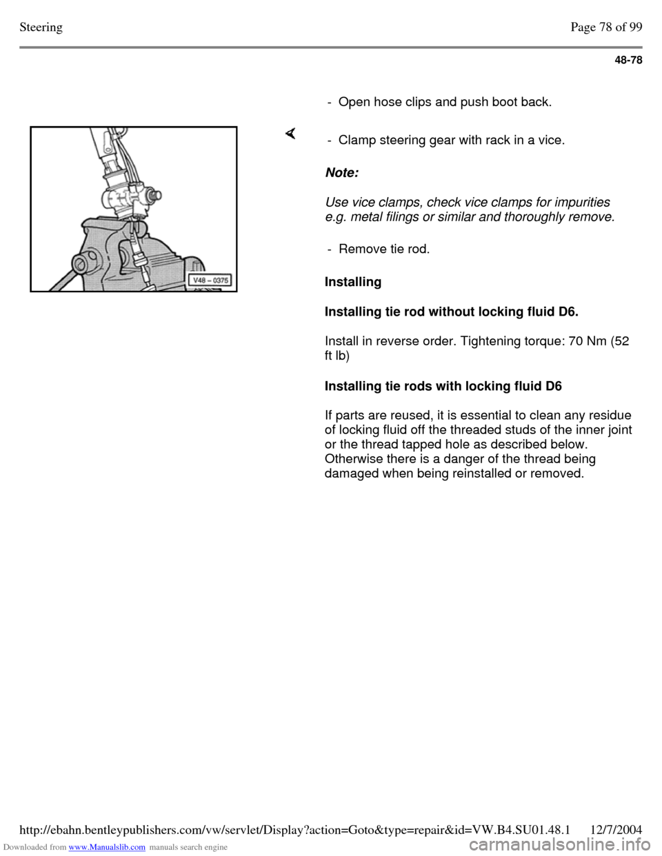
- Open hose clips and push boot back. Note:
Use vice clamps, check vice clamps for impurities
e.g. metal filings or similar and thoroughly remove.
Installing
Installing tie rod without locking fluid D6.
Install in reverse order. Tightening torque: 70 Nm (52
ft lb)
Installing tie rods with locking fluid D6
If parts are reused, it is essential to clean any residue
of locking fluid off the threaded studs of the inner joint
or the thread tapped hole as described below.
Otherwise there is a danger of the thread being
damaged when being reinstalled or removed. - Clamp steering gear with rack in a vice. - Remove tie rod. Page 78 of 99Steering12/7/2004http://ebahn.bentleypublishers.com/vw/servlet/Display?action=Goto&type=repair&id=VW.B4.SU01.48.1
Page 350 of 369
Downloaded from www.Manualslib.com manuals search engine 48-80
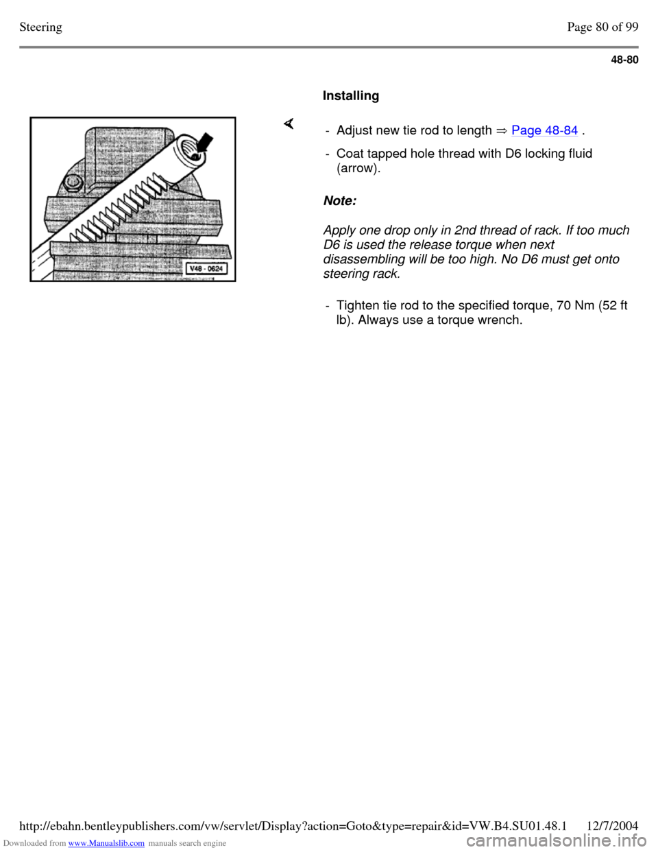
Installing Note:
Apply one drop only in 2nd thread of rack. If too much
D6 is used the release torque when next
disassembling will be too high. No D6 must get onto
steering rack. - Adjust new tie rod to length Page 48-84 . - Coat tapped hole thread with D6 locking fluid
(arrow).
- Tighten tie rod to the specified torque, 70 Nm (52 ft lb). Always use a torque wrench. Page 80 of 99Steering12/7/2004http://ebahn.bentleypublishers.com/vw/servlet/Display?action=Goto&type=repair&id=VW.B4.SU01.48.1