VOLKSWAGEN TRANSPORTER 2012 Owners Manual
Manufacturer: VOLKSWAGEN, Model Year: 2012, Model line: TRANSPORTER, Model: VOLKSWAGEN TRANSPORTER 2012Pages: 486, PDF Size: 69.28 MB
Page 151 of 486
A WARNING (Continued)
• Never stow lighters in stowage areas or compartments or on other surfaces In the ve-hicle. Cigarette lighters may self-Ignite on high-temperature surfaces, especially in sum-mer.
CD
• Hard objects on the shelf can chafe against the wires of the heating element In the rear win-dow and cause damage.
• Objects stored In the vehicle that are made from transparent materials, such as glasses, magnifying glasses or transparent suction cups on the windows, can concentrate the sun's rays and thus cause damage to the vehi-cle.
r:F1 Always ensure that the ventilation openings W between the rear window and the stowage area are uncovered to allow stale air to escape from the vehicle.
r('n First read and observe the introductory L-Jc.lJ information and safety warnings.& on page 150.
There is a stowage compartment in the centre con-sole, which. depending on the vehicle equipment level, may have a cover flap.
To open, press the button on the cover flap. The stowage compartment opens automatically.
To close, press the cover down until it engages. Do not press the button while doing this.
Depending on the vehicle equipment level, there may be open stowage compartments under the vents on the dash panel.
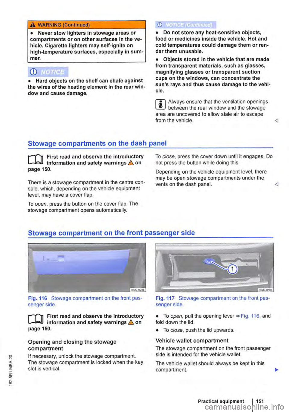
Fig. 116 Stowage compartment on the front pas-senger side.
r('n First read and observe the introductory L-Jc.lJ Information and safety warnings.& on page 150.
Opening and closing the stowage compartment
If necessary, unlock the stowage compartment. The stowage compartment is locked when the key slot is vertical.
Fig. 117 Stowage compartment on the front pas-senger side.
• To open, pull the opening lever =:.Fig. 116, and fold down the lid.
• To close. push the lid upwards.
Vehicle wallet compartment
The stowage compartment on the front passenger side is intended for the vehicle wallet.
The vehicle wallet should always be kept in this compartment. .,.
Practical equipment 1151
Page 152 of 486
Cooling the stowage compartment
There is a vent in the rear panel 117 Q). If the air conditioning is switched on, cooled air can be directed into the compartment. Turn the vents to open and close them.
A WARNING
If the stowage compartment on the front pas-senger side is left open, this can Increase the risk of serious injury In the event of an acci-dent or during sudden braking or driving ma-noeuvres.
Other stowage compartments
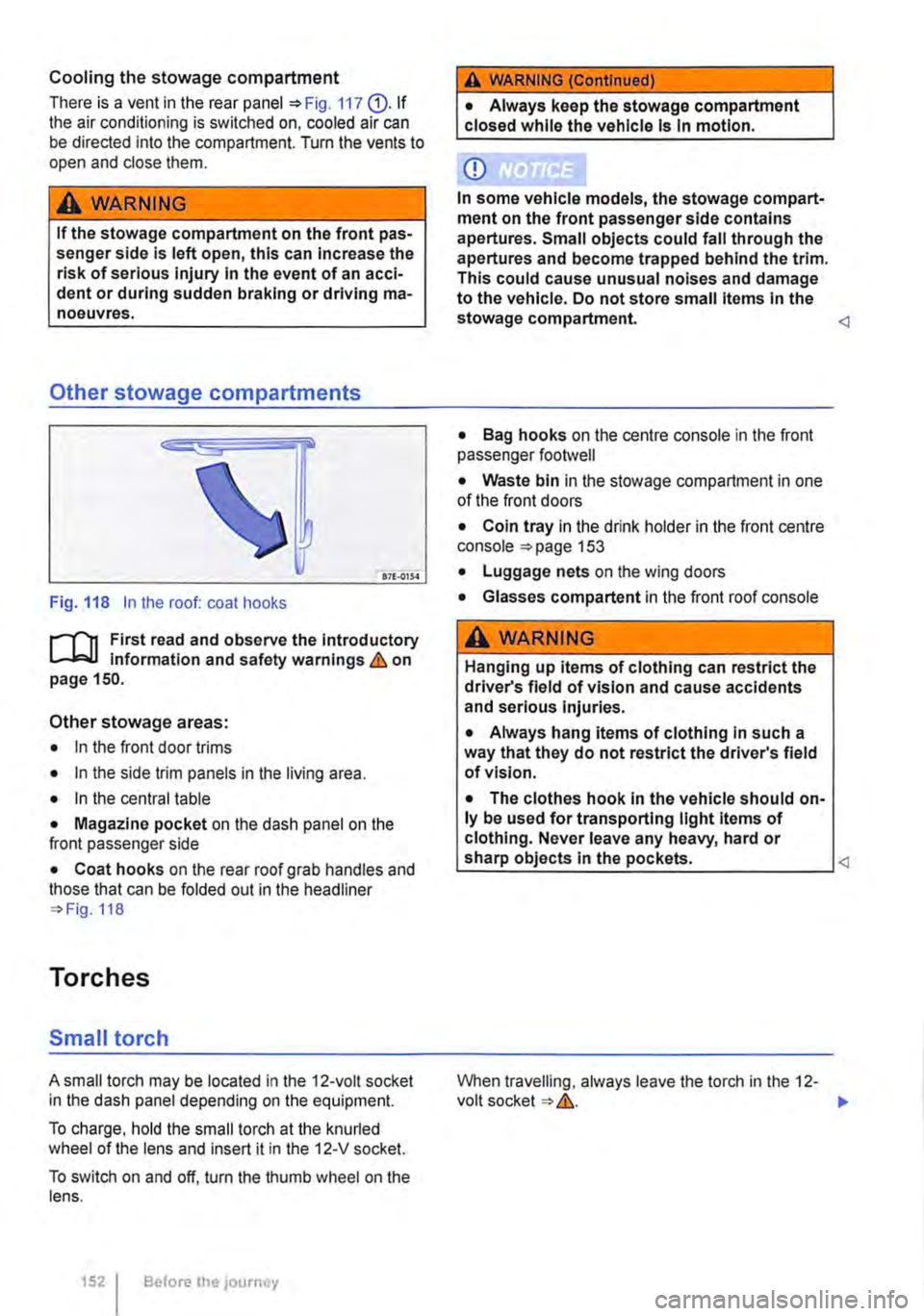
Fig. 118 In the roof: coat hooks
r-T'n First read and observe the Introductory 1...-J,:.lJ information and safety warnings&. on page 150.
Other stowage areas:
• In the front door trims
• In the side trim panels in the living area.
• In the central table
• Magazine pocket on the dash panel on the front passenger side
• Coat hooks on the rear roof grab handles and those that can be folded out in the headliner 118
Torches
Small torch
A small torch may be located in the 12-volt socket in the dash panel depending on the equipment.
To charge, hold the small torch at the knurled wheel of the lens and insert it in the 12-V socket.
To switch on and off, turn the thumb wheel on the lens.
1521 Before the journey
A WARNING (Continued)
• Always keep the stowage compartment closed while the vehicle Is In motion.
CD
In some vehicle models, the stowage compart-ment on the front passenger side contains apertures. Small objects could fall through the apertures and become trapped behind the trim. This could cause unusual noises and damage to the vehicle. Do not store small Items In the stowage compartment.
• Bag hooks on the centre console in the front passenger footwell
• Waste bin in the stowage compartment in one of the front doors
• Coin tray in the drink holder in the front centre console 153
• Luggage nets on the wing doors
• Glasses compartent in the front roof console
A WARNING
Hanging up items of clothing can restrict the driver's field of vision and cause accidents and serious Injuries.
• Always hang items of clothing In such a way that they do not restrict the driver's field of vision.
• The clothes hook In the vehicle should on-ly be used for transporting light Items of clothing. Never leave any heavy, hard or
When travelling, always leave the torch in the 12-volt socket &.. ..,.
Page 153 of 486
A WARNING
Objects that are not secured, or are secured Incorrectly, can cause serious Injuries In the event of a sudden driving or braking manoeu·
Torch behind front passenger seat
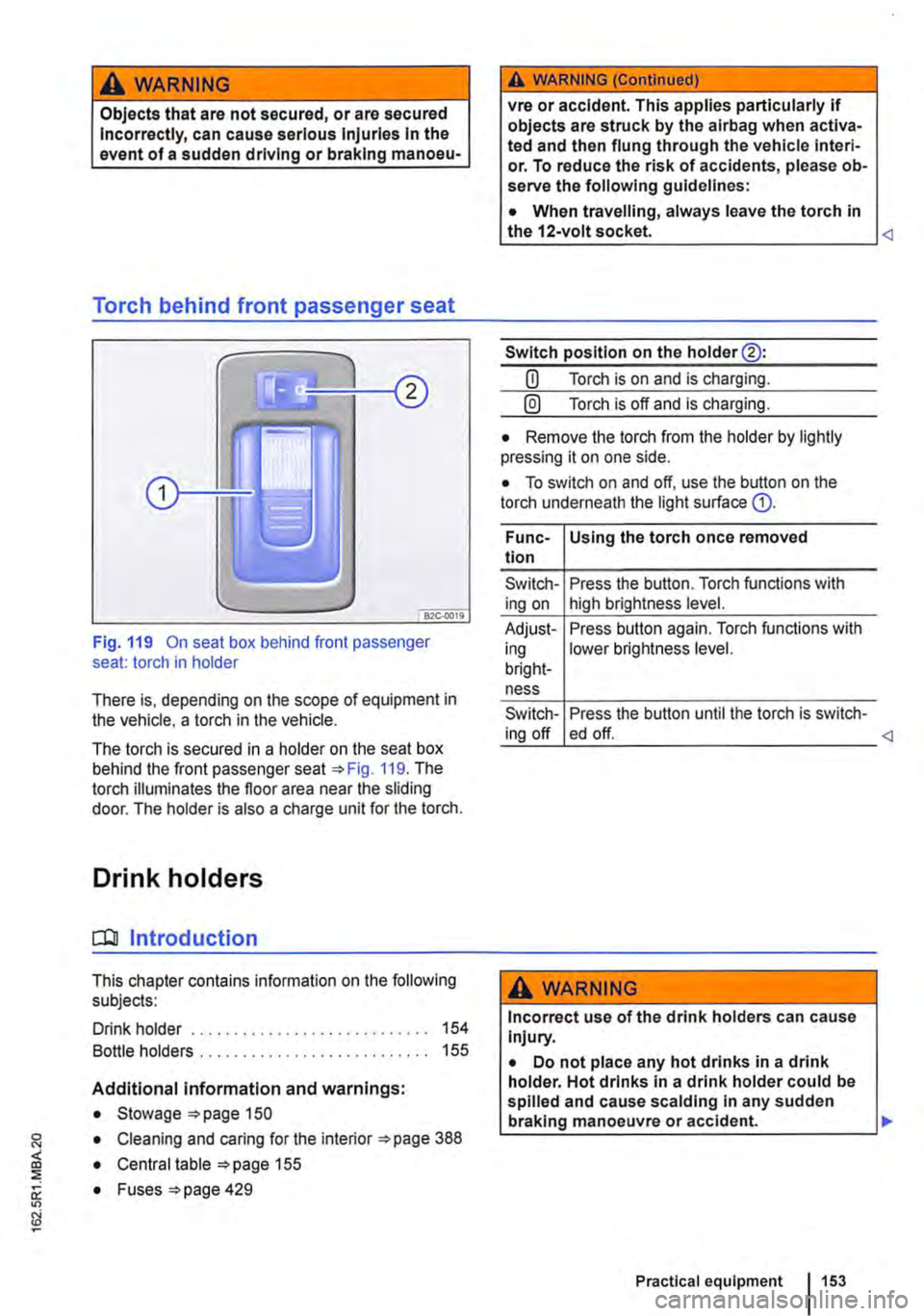
Fig. 119 On seat box behind front passenger seat: torch in holder
There is, depending on the scope of equipment in the vehicle, a torch in the vehicle.
The torch is secured in a holder on the seat box behind the front passenger seat 119. The torch illuminates the floor area near the sliding door. The holder is also a charge unit for the torch.
Drink holders
CQJ Introduction
This chapter contains information on the following subjects:
Drink holder . . . . . . . . . . . . . . . . . . . . . . . . . . . . 154
Bottle holders . . . . . . . . . . . . . . . . . . . . . . . . . 155
Additional information and warnings:
• Stowage 150
• Cleaning and caring for the interior 388
• Central table 155
0: • Fuses =>page 429
"'
A WARNING (Continued)
vre or accident. This applies particularly if objects are struck by the airbag when activa-ted and then flung through the vehicle interi· or. To reduce the risk of accidents, please ob-serve the following guidelines:
• When travelling, always leave the torch in the 12-volt socket.
Switch position on the holder@:
CD Torch is on and is charging.
@) Torch is off and is charging.
• Remove the torch from the holder by lightly pressing it on one side.
• To switch on and off, use the button on the torch underneath the light surface G).
Func-Using the torch once removed tion
Switch-Press the button. Torch functions with ing on high brightness level.
Adjust-Press button again. Torch functions with ing lower brightness level. bright-ness
Switch-Press the button until the torch is switch-ing off ed off.
A WARNING
Incorrect use of the drink holders can cause Injury.
• Do not place any hot drinks in a drink holder. Hot drinks in a drink holder could be spilled and cause scalding In any sudden braking manoeuvre or accident. .,.
Practical equipment 153
Page 154 of 486
A WARNING (Continued)
• Ensure that drink bottles or any other ob-jects do not enter the driver footwell and ob-struct the pedals while the vehicle is in mo-tion.
• Never place heavy cups, food or any other heavy items in the drink holder. These heavy objects could be flung through the vehicle in-terior during an accident and cause serious injuries.
A WARNING
Closed drink bottles can explode in the vehi-cle In extreme heat or crack in extremely cold temperatures.
• Never leave closed drink bottles in an ex-tremely hot or extremely cold vehicle for ex-tended periods.
Drink holder
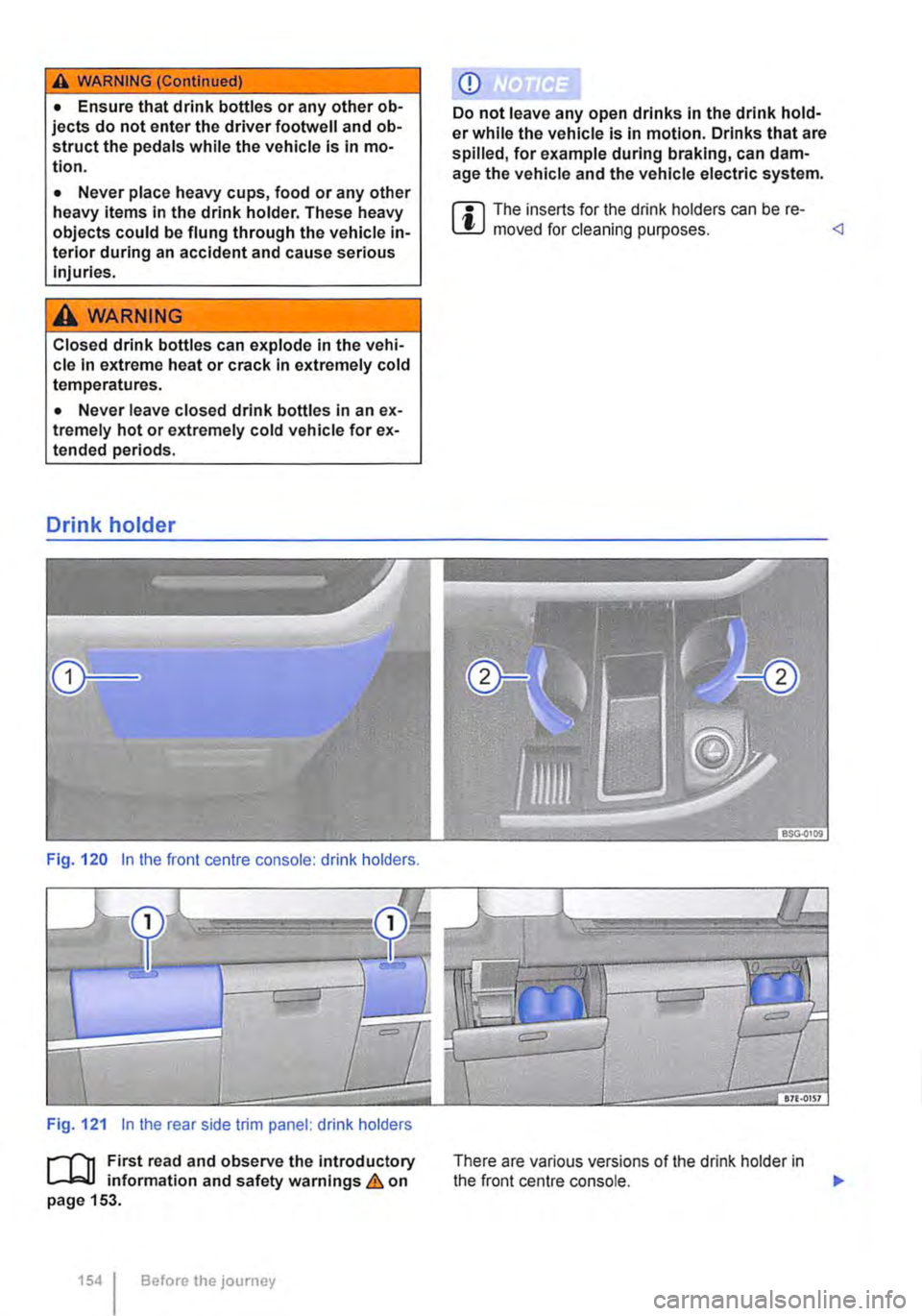
Fig. 120 In the front centre console: drink holders.
Fig. 121 In the rear side trim panel: drink holders
r--T'n First read and observe the introductory L..Jo:.U information and safety warnings & on page 153.
1541 Before the journey
CD
Do not leave any open drinks in the drink hold-er while the vehicle is in motion. Drinks that are spilled, for example during braking, can dam-age the vehicle and the vehicle electric system.
W The inserts for the drink holders can be re-L!J moved for cleaning purposes.
Page 155 of 486
Opening the drink holder in the centre console
• Press onto drink holder "'Fig. 120 G). The drink holder will then open automatically.
• Push the holder® slightly to the side and place the bottle or can into the drink holder.
Opening and closing the drink holder in the rear side trim panel
• Press button "'Fig. 121 G). The drink holder will then open automatically.
Bottle holders
1"'111 First read and observe the introductory L-J,::.ll information and safety warnings & on page 153.
Depending on the vehicle equipment level, the bot-tle holders may be found at the following locations:
• In the front door trims
• In the lower section of the centre console
• In the side trim panels in the living area.
• In the central table
Opening and closing the bottle holder in the centre console
• To open, pull the handle of the bottle holder. The bottle holder will then open automatically.
• To close, push the bottle holder until it clicks in-to place.
Tables
o:::n Introduction
This chapter contains information on the following subjects:
Folding table in the side panel . . . . . . • . . . . . . 156 Central table . . . . . . . . . . . . 156
Additional information and warnings:
• Stowage "'page 150
• Drink holder 153
Opening the drink holder in the central table
• Press lhe symbol i on the cover of the drink holder and pull the drink holder out fully.
Closing the drink holder
• Remove the bottle or can.
• Push the drink holder in until it engages secure-
Bottle holder in the central table
The bottle holder in the central table can be ac-cessed after the table module has been raised.
m The bottle holder in the centre console must W be removed to gain access to the fuses in Multivan with left-hand drive 429.
A WARNING
Improper use of the tables could cause seri-ous injury.
• Never use the tables while the vehicle is in motion.
• All tables must be securely stowed while the vehicle is In motion.
• Never sit or stand on the tables.
CD
Never place hot objects, such as pots or pans, on the tables. Such objects could damage these surfaces.
Practical equipment 155
Page 156 of 486
Folding table in the side panel
l
1---c:J--'
t,J
171·0160
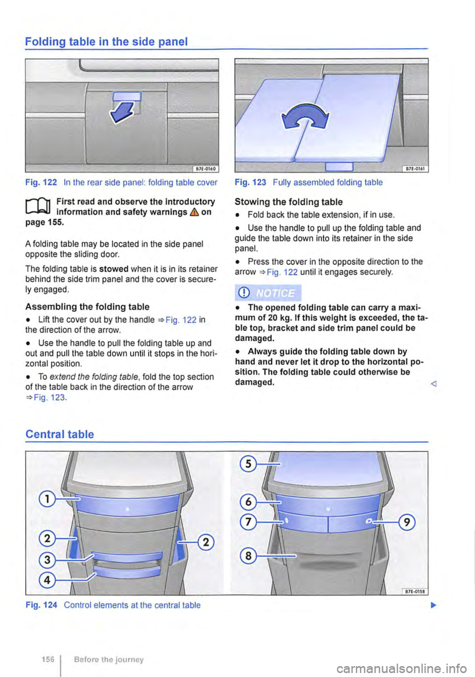
Fig. 122 In the rear side panel: folding table cover
f"'"""'(""'n First read and observe the Introductory Information and safety warnings & on page 155.
A folding table may be located in the side panel opposite the sliding door.
The folding table is stowed when it is in its retainer behind the side trim panel and the cover is secure-ly engaged.
Assembling the folding table
• Lift the cover out by the handle 122 in the direction of the arrow.
• Use the handle to pull the folding table up and out and pull the table down until it stops in the hori-zontal position.
• To extend the folding table, fold the top section of the table back in the direction of the arrow 123.
Central table
Fig. 124 Control elements at the central table
156 I Before the journey
Fig. 123 Fully assembled folding table
Stowing the folding table
• Fold back the table extension, if in use.
• Use the handle to pull up the folding table and guide the table down into its retainer in the side panel.
• Press the cover in the opposite direction to the arrow 122 until it engages securely.
CD
• The opened folding table can carry a maxi-mum of 20 kg. If this weight is exceeded, theta-ble top, bracket and side trim panel could be damaged.
• Always guide the folding table down by hand and never let it drop to the horizontal po-sition. The folding table could otherwise be damaged.
Page 157 of 486
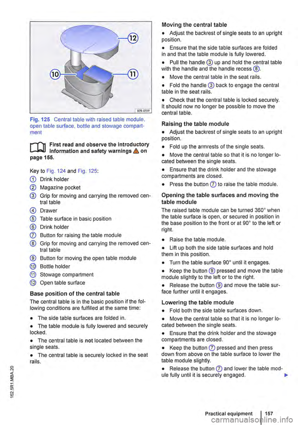
Fig. 125 Central table with raised table module, open table surface. bottle and stowage compart-ment
r-1'11 First read and observe the Introductory l.-Jr:-lJ Information and safety warnings & on page 155.
Key to Fig. 124 and Fig. 125:
G) Drink holder
0 Magazine pocket
® Grip for moving and carrying the removed cen-tral table
@ Drawer
® Table surface in basic position
® Drink holder
0 Button for raising the table module
® Grip for moving and carrying the removed cen-tral table
® Button for moving the open table module
® Bottle holder
® Stowage compartment
@ Open table surface
Base position of the central table
The central table is in the basic position if the fol-lowing conditions are fulfilled at the same time:
• The side table surfaces are folded in.
• The table module is fully lowered and securely locked.
• The central table is not located between the single seats.
• The central table is securely locked in the seat rails.
Moving the central table
• Adjust the backrest of single seats to an upright position.
• Ensure that the side table surfaces are folded in and that the table module is fully lowered.
• Pull the handle® up and hold the central table wilh the handle and the handle recess @.
• Move the central table in the seat rails.
• Fold the handle® back to engage the central table in the seat rails.
• Check that the central table is locked securely. lt should now no longer be possible to move the central table.
Raising the table module
• Adjust the backrest of single seats to an upright position.
• Fold up the armrests of the single seats.
• Move the central table so that it is no longer lo-cated between the single seats.
• Ensure that the drink holder and the stowage compartments are closed.
• Press the button 0 to raise the table module.
Opening the table surfaces and moving the
table module
The raised table module can be turned 36o• when the table surface is open, or secured in position in the base position to the front or at go• to the left or rig hi.
• Raise lhe table module.
• Lift up both the side table surfaces and hold them in this position.
• Turn the table surface go• until it engages.
• Keep the button ® pressed and move the table module slightly to the left or to the right.
• Release the button ® and move the table sur-face further until it engages.
Lowering the table module
• Fold both the side table surfaces down.
• Move the central table so that it is no longer lo-cated between the single seats.
• Ensure that the drink holder and the stowage compartments are closed.
• Keep the button 0 pressed and then press down from above on the table surface to lower the table module slightly.
• Release the button 0 and lower lhe table mod-ule fully until it is securely engaged. .,.
Practical equipment 1157
Page 158 of 486
Removing the central table
The central table can be removed more easily by two people than by one person.
• Remove front protective covers from the central seat rails.
• Turn the single seats so that they face the di-rection of travel.
• Adjust the back rest of single seats to an upright position.
• Fold up the armrests of the single seats.
• Pull the handle @ up and hold the central table with the handle and the handle recess@.
• Push the central table forwards to the point where it can be lifted out of the slots in the seat rails.
• Lift the central table out.
• Put down the central table carefully so that the rollers and feet are not soiled or damaged.
• Place the removed covers on the open slots in the seat rails.
Fitting the central table
The central table can be installed more easily by two people than by one person.
• Remove front protective covers from the central seat rails.
• Turn the single seats so that they face the di-rection of travel.
Cool box
c:cn Introduction
This chapter contains information on the following subjects:
Fitting and removing the cool box
Switching the cool box on and off 159 161
The cool box may be used while the vehicle is in motion only if it is fitted to the adapter plate.
Power for the cool box can be supplied by any of the 12-volt sockets in the vehicle. The power con-sumption is approx. 33 watts. The cool box has a capacity of 32 litres.
Follow instructions provided for the installation and use of the cool box and keep it in the vehicle wal-let.
As far as possible, keep food and drinks in the cool box in leak-proof containers. Do not overfill the cool box such that air circulation is impaired.
158 Before the journey
• Adjust the backrest of single seats to an upright position.
• Fold up the armrests of the single seats.
• Pull the handle @ up and hold the central table with the handle and the handle recess®.
• Insert the central table guides into the recesses in the seat rails.
• Insert the central table into the seat rails and push them back, so that the removed covers can be placed on the open slots in the seat rails.
• Fold the handle@ back to engage the central table in the seat rails.
• Check that the central table is locked securely. it should now no longer be possible to move the central table.
• Do not raise the table module when the cen-tral table Is located between the single seats. This could cause damage to the table.
The vehicle battery will be drained if the cool box is used when the engine is switched off. For this rea-son, the cool box is fitted with a battery monitor. The battery monitor will switch the cool box off if the vehicle battery has a low charge level. The bat-tery monitor will switch the cool box on again as soon as the battery has reached a suitable charge level, for example, after a long journey.
Additional information and warnings:
• Seat functions, front =>page 69
• Seat functions, rear =>page 72
• Seat functions, rear, Business =>page 182
• Seat functions, rear, California =>page 193
• Electrical sockets =>page 163
• Battery =>page 350
Page 159 of 486
• Cleaning and caring for the interior =:>page 380
• Accessories. modifications, repairs and renewal of parts =:>page 380
A WARNING
Objects that are not secured, or are secured Incorrectly, can cause serious Injuries In the event of a sudden driving or braking manoeu-vre or accident
• The cool box may be transported only if it Is fitted to the adapter plate.
• Make sure that the adapter plate is proper-ly fitted In the seat rails.
• The cool box lid must always be closed and latched when the vehicle Is In motion.
• Never use the cool box as a table or stow-age compartment when the vehicle Is In mo-tlon.
A WARNING
If the ambient temperature In the vehicle is too low, the temperature in the cool box could fall below +2•c (+35°F) degrees. This could cause the contents of the cool box to freeze and bottles and other containers to burst, potentially causing injuries.
• Do not use the cool box when the ambient temperature is too low.
CD
This could damage the cool box if the bed ex-tension is fitted (multi-flex board).
Fitting and removing the cool box
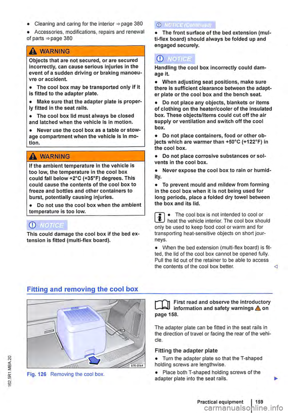
Fig. 126 Removing the cool box.
CD
• The front surface of the bed extension (mul-ti-flex board) should always be folded up and engaged securely.
CD
Handling the cool box Incorrectly could dam-age it
• When adjusting seat positions, make sure there Is sufficient clearance between the adapt-er plate or the cool box and the bench seat.
• Do not place any objects, blankets or items of clothing on the heater/cooler of the Insulated box. These objects/Items could cut off the air supply or ventilation and switch off the cool box.
• Do not place containers, food or other ob-jects which are warmer than +so•c (+122.F) in the cool box.
• Do not place corrosive substances or sol-vents In the cool box.
• Never expose the cool box to rain or humid-Ity.
• To prevent mould and mildew from forming in the cool box when it is not being used for long periods, place a folded dry towel between the box and its lid.
m • The cool box is not intended to cool or L!J heat the vehicle interior. The cool box should only be used to keep food cool or warm and for transporting heat-sensitive objects on short jour-neys.
• When the bed extension (multi-flex board) is fit-ted, the lid of the cool box cannot be opened fully. Pull the lid out of the retainer to be able to access the contents of the cool box better.
,...--("n First read and observe the Introductory L--J,:.U information and safety warnings & on page 158.
The adapter plate can be fitted in the seat rails in the direction of travel or facing the rear of the vehi-cle.
Fitting the adapter plate
• Turn the adapter plate so that the T-shaped holding screws are lengthwise.
• Place both T-shaped holding screws of the adapter plate into the seat rails.
Practical equipment 1159
Page 160 of 486
• Push both handles down.
• Turn both handles through go• so that the T-shaped holding screws are across the seat rails
• Tighten both the thumb wheels firmly.
• When fitting the adapter plate ensure sufficient clearance between the adapter plate or the cool box and the bench seat
Fitting the cool box
• Fit the adapter plate.
• Pull out the handle on the adapter plate.
• Place the cool box on the adapter plate.
• Make sure that all holding screws on the cool box are fully engaged in the corresponding holes on the adapter plate &..
• Pull the handle on the adapter plate right out.
• When fitting the cool box ensure sufficient clearance between the adapter plate or the cool box and the bench seat
Removing the cool box
• Pull out the handle on the adapter plate in the direction of the arrow 126 to unlock the cool box.
• Lift up the cool box to remove it.
• Pull the handle on the adapter plate right out.
Removing the adapter plate
• Remove the cool box.
• Turn the adapter plate so that the T-shaped holding screws are lengthwise.
• Lift up the adapter plate to remove it.
A WARNING
Objects that are not secured, or are secured incorrectly, can cause serious Injuries in the event of a sudden driving or braking manoeu-vre or accident.
160 I Before the journey
A WARNING (Continued)
• Make sure that the T-shaped holding screws In the seat rails are at right-angles (90°) to the adapter plate and correctly engag-ed.
• The T-shaped holding screws should nev-er be Inserted In the seat rails near the re-movable covers.
• Make sure that the cool box Is properly fit-ted In on the adapter plate.
CD
Handling the cool box Incorrectly could dam-agelt.
• When adjusting seat positions, make sure there Is sufficient clearance between the adapt-er plate or the cool box and the bench seat.
• Do not place any objects, blankets or Items of clothing on the heater/cooler of the Insulated box. These objects/Items could cut off the air supply or ventilation and switch off the cool box.
• Do not place containers, food or other ob-jects which are wanner than +5o•c (+122.F) In the cool box.
• Do not place corrosive substances or sol-vents In the cool box.
• Never expose the cool box to rain or humid-ity.
• To prevent mould and mildew from fonnlng In the cool box when it Is not being used for long periods, place a folded dry towel between the box and Its lid.