VOLKSWAGEN TRANSPORTER 2012 Owners Manual
Manufacturer: VOLKSWAGEN, Model Year: 2012, Model line: TRANSPORTER, Model: VOLKSWAGEN TRANSPORTER 2012Pages: 486, PDF Size: 69.28 MB
Page 221 of 486
Electric pop-up roof, California
o:IJ Introduction
This chapter contains information on the following subjects:
Opening the electric pop-up roof . . . . . . . . . . . 222
Closing the electric pop-up roof . . . 223
Preliminary work for closing the electric pop-up roof manually . . . . . . . . . . . . . . . . . . . . . . . . 224
Closing the electric pop-up roof manually . 225 Securing the pop-up roof manually from outside the vehicle . . . . . 225
Roller shutter
Above the front seats there is a roller shutter, which must always be closed while the vehicle is in motion. This prevents the pop-up roof canvas from hanging down through the ceiling access and blocking the driver's view. Keeping the roller shut-ter closed also reduces wind noise while the vehi-cle is in motion.
Additional information:
• Central control panel 204
• Rectifying faults on the camping equipment 254
• Winter conditions 253
• Vehicle tool kit 416
A WARNING
Incorrect handling of the pop-up roof can cause accidents and serious Injuries.
• Never drive the vehicle with the pop-up roof open. The pop-up roof must always be completely closed and securely locked while the vehicle Is In motion.
• Never drive with people In the pop-up roof.
• Only open or close the pop-up roof while the vehicle Is stationary.
• Only mount a luggage roof rack when the pop-up roof is completely closed and secure-ly locked.
A WARNING
Careless or inattentive use of the pop-up roof could cause serious Injuries.
• The pop-up roof should only be opened or closed when you are sure that nobody is in its operating area.
A WARNING (Continued)
• Never leave children or people requiring assistance alone In the vehicle.
• Always take all vehicle keys with you ev-ery time you leave the vehicle.
A WARNING
Driving at high vehicle speeds and with a strong headwind after closing the pop-up roof manually could cause the pop-up roof to lift up or open on Its own and potentially cause serious Injuries.
• If you close the pop-up roof manually, do not drive faster than 60 km/h.
• Drive especially carefully and slowly In the presence of a strong headwind.
• The pop-up roof should be checked by a qualified workshop as soon as possible.
CD
Incorrect handling of the pop-up roof can cause damage to it or to other parts of the vehi-cle.
• Make sure there is adequate space before opening the pop-up roof.
• When closing the pop-up roof, always open the roller shutter and one of the vehicle doors to allow the excess air pressure to escape.
• Only close the pop-up roof when it is dry to prevent the build up of mould or mildew.
• Open the pop-up roof occasionally to air it out when it is not being used for long periods of time.
• Clean the pop-up roof bellows with water only. Never use household cleaners or Impreg-nating fabric treatment products.
• Close the pop-up roof during storms with driving rain and wind gusts. Otherwise the bel-lows could leak despite their specially treated fabric.
m Roof hydraulics: the pop-up height of the W pop-up roof will be checked automatically and altered if necessary at regular intervals after the ignition has been switched off and the ignition key removed: first after 10 hours and then every five hours. .,.
Equipment, California 221
Page 222 of 486
m If the pop-up roof cannot be closed even l!J when the ignition is switched on and the clos-ing function is used, please check all possible cau-ses. If the cause cannot be found or there are oth-er malfunctions, please close the pop-up roof man-
Opening the electric pop-up roof
r--'('n First read and observe the introductory L-.lo:.U information and safety warnings & on page 221.
Opening the pop-up roof
• Switch on the ignition.
• Switch on the central control panel.
• Open the roller shutter and release the reading lamp retaining strap.
• Select the menu option Pop-up roof in the central control panel.
• Select menu option Open (dark background).
• Press and hold the rotary/push knob until the hydraulic motor has switched off automatically and the pop-up roof has opened fully. The symbol for the open pop-up roof will be displayed. The hy-draulic motor has a run-on time of approx. 5 sec-onds to bleed the hydraulic system.
• Switch off the ignition and remove the ignition key.
• Push up the bed panel to increase standing room.
Opening and closing the windows in the canvas
• To Open, unzip and fold down the canvas.
• To Close, fold the canvas back up and zip com-pletely closed.
The insect screen is sewn into the canvas and cannot be opened.
Bed in pop-up roof
• Step carefully onto the seat cushion of the front seats and support yourself on the edge of the bed when climbing up to the pop-up roof bed &.
Fitting the safety net for the pop-up roof bed
Always fit the safety net when children sleep in or otherwise occupy the pop-up roof bed &.
222 I Before the journey
ually 224, and drive carefully and at re-duced speed to the nearest qualified workshop. Volkswagen Commercial Vehicles recommends us-ing a Volkswagen Commercial Vehicles dealership for this purpose.
• Lift the mattress on the roof bed and attach the bottom of the safety net to the now accessible press studs in the bed panel.
• Observe the safety instructions on the sticker on the front side of the bed panel
A WARNING
Always take care when climbing Into and out of the pop-up roof bed, otherwise you could cause serious injury to yourself or others.
• Never step on or support yourself with the front seat armrests or head restraints.
• Never step on or support yourself with the closed roller shutter.
• Never jump off the pop-up roof bed. Al-ways take care while climbing down.
• Help others, especially children, to climb up and down safely.
A WARNING
If the safecy net is not fitted or not properly fitted, children could fall off the pop-up roof bed and seriously Injure themselves.
• Always fit the safety net when children sleep In or otherwise occupy the pop-up roof bed.
m Volkswagen Commercial Vehicles recom-l!J mends that small children not be allowed to sleep in the pop-up roof bed. <
Page 223 of 486
Closing the electric pop-up roof
j'"'('n First read and observe the introductory information and safety warnings & on page 221.
• Close all of the windows in the pop-up roof can-vas.
• Remove the children's safety net.
• Lower the bed panel.
• Ensure that the roller shutter is and stays open.
• Make sure that no people or objects, such as blankets or pillows, are on the upper bed. Position the mattress correctly.
• Disconnect any connected devices from the 12-volt socket in the roof frame, and stow them in a safe place in the vehicle.
• Switch on the ignition.
• Open one of the vehicle doors to allow excess air pressure to escape.
• Switch on the central control panel.
• Select the menu option Pop-up roof in the central control panel.
• Select menu option Close (dark background).
• Press and hold the rotary/push knob for ap-proximately four seconds. An acoustic signal is giv-en and the display reads for approximately four seconds Roof bed down? Shutter open? Window open?. All control elements for the pop-up roof are blocked during this safety check.
• Press and hold the rotary/push knob again to continue closing. Make sure that the canvas is not pinched at the front or on the side between the ve-hicle and the roof or the rods.
• Press and hold the rotary/push knob until the hydraulic motor has switched off automatically and the pop-up roof has closed fully. This is shown by the .t symbol in the display. The hydraulic motor has a run-on time of approx. 5 seconds to bleed the hydraulic system.
• Close the roller shutter. Make sure that the can-vas is not pinched.
m The LED lights in the pop-up roof are switch-L!..J ed off automatically as soon as the engine is
Equipment, California I 223
Page 224 of 486
Preliminary work for closing the electric pop-up roof manually
Fig. 184 Removing the cover on the interior lights control panel
Fig. 185 Removing the central control panel
r-T'n First read and observe the Introductory L-W.l Information and safety warnings & on page 221.
• Take the screwdriver from the vehicle tool kit 416.
• Close all of the windows in the pop-up roof can-vas.
• Lower the bed panel.
• Ensure that the roller shutter is and stays open.
• Secure the reading light to the cushion with the retaining strap.
• Make sure that no people or objects, such as blankets or pillows, are on the upper bed. Position both mattresses correctly.
• Open one of the vehicle doors to allow excess air pressure to escape.
224 I Before the journey
• Switch off the ignition.
• Open the glasses compartent in the roof con-sole.
• Grasp the interior lights control panel cover from behind through the slots and carefully press the Fig. 184 CD out of its fitting.
• Carefully press in the four clips between the roof console and the central control panel 185 the flat edge of a screwdriver.
• Pull the central control panel gently in the direc-tion of arrow CD [ID and then upwards out of its fit-ting in the direction of arrow ®[ID.
CD
Be careful when removing the central control panel and cover so as not to cause damage.
Page 225 of 486
Closing the electric pop-up roof manually
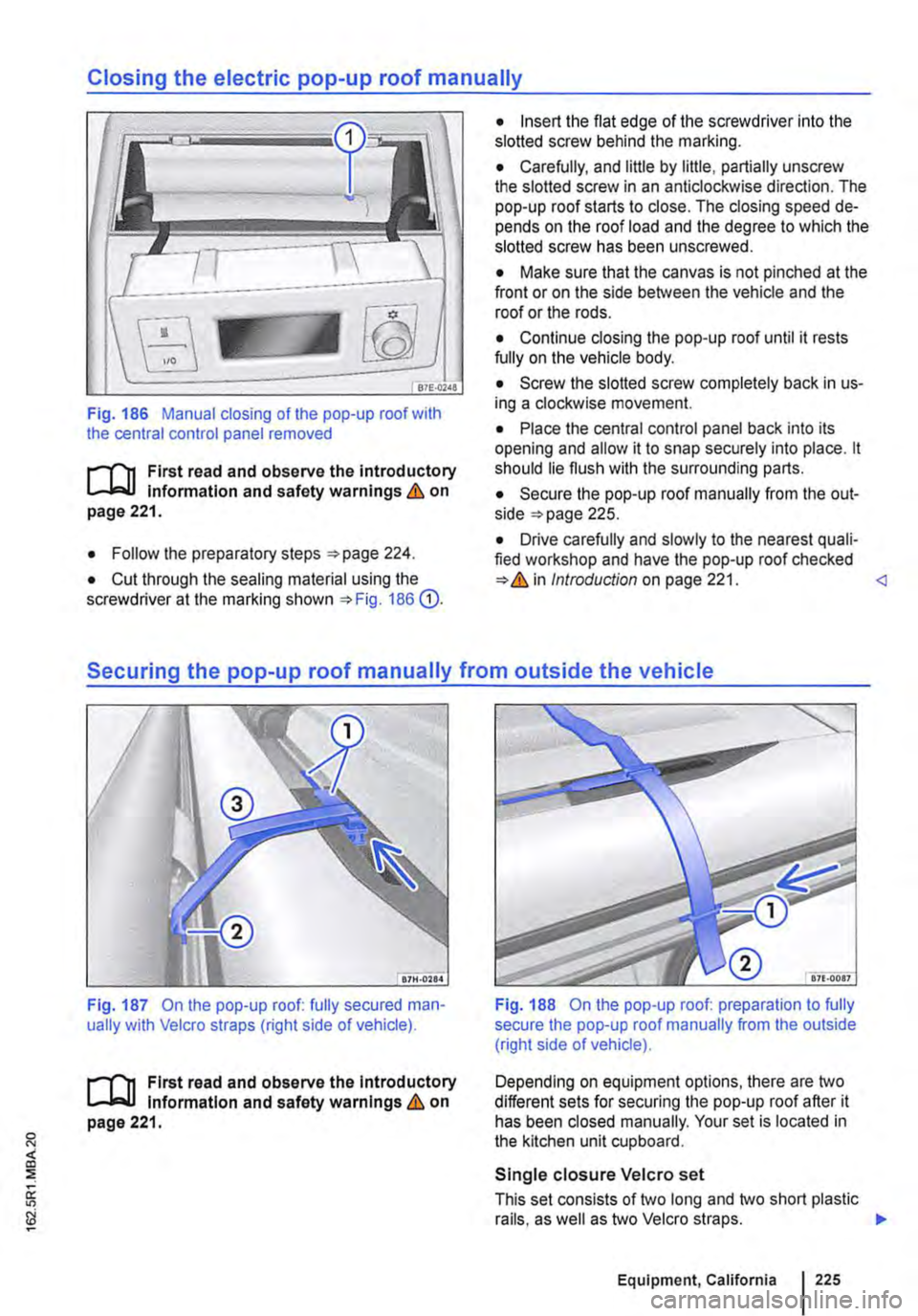
Fig. 186 Manual closing of the pop-up roof with the central control panel removed
t'""('n First read and observe the introductory Information and safety warnings & on page 221.
• Follow the preparatory steps 224.
• Cut through the sealing material using the screwdriver at the marking shown 186 G).
• Insert the flat edge of the screwdriver into the slotted screw behind the marking.
• Carefully, and little by little, partially unscrew the slotted screw in an anticlockwise direction. The pop-up roof starts to close. The closing speed de-pends on the roof load and the degree to which the slotted screw has been unscrewed.
• Make sure that the canvas is not pinched at the front or on the side between the vehicle and the roof or the rods.
• Continue closing the pop-up roof until it rests fully on the vehicle body.
• Screw the slotted screw completely back in us-ing a clockwise movement.
• Place the central control panel back into its opening and allow it to snap securely into place. lt should lie flush with the surrounding parts.
• Secure the pop-up roof manually from the out-side 225.
• Drive carefully and slowly to the nearest quali-fied workshop and have the pop-up roof checked Introduction on page 221.
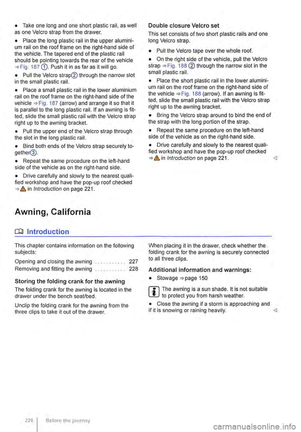
Fig. 187 On the pop-up roof: fully secured man-ually with Velcro straps (right side of vehicle).
t'""('n First read and observe the Introductory Information and safety warnings & on page 221.
Fig. 188 On the pop-up roof: preparation to fully secure the pop-up roof manually from the outside (right side of vehicle).
Depending on equipment options, there are two different sets for securing the pop-up roof after it has been closed manually. Your set is located in the kitchen unit cupboard.
Single closure Velcro set
This set consists of two long and two short plastic rails, as well as two Velcro straps. .,.
Equipment, California 225
Page 226 of 486
• Take one long and one short plastic rail. as well as one Velcro strap from the drawer.
• Place the long plastic rail in the upper alumini-um rail on the roof frame on the right-hand side of the vehicle. The tapered end of the plastic rail should be pointing towards the rear of the vehicle 187 G). Push it in as far as it will go.
• Pull the Velcro strap@ through the narrow slot in the small plastic rail.
• Place a small plastic rail in the lower aluminium rail on the roof frame on the right-hand side of the Fig. 187 (arrow) and arrange it so that it is parallel to the long plastic rail. If an awning is fit-ted, slide the small plastic rail with the Velcro strap right up to the awning bracket.
• Pull the upper end of the Velcro strap through the slot in the long plastic rail.
• Bind both ends of the Velcro strap securely to-gether@.
• Repeat the same procedure on the left-hand side of the vehicle as on the right-hand side.
• Drive carefully and slowly to the nearest quali-fied workshop and have the pop-up roof checked & in Introduction on page 221.
Awning, California
a:n Introduction
This chapter contains information on the following subjects:
Opening and closing the awning . . . . . . • . . . . 227
Removing and fitting the awning . . . . . . . . . . . 228
Storing the folding crank for the awning
The folding crank for the awning is located in the drawer under the bench seaVbed.
Unclip the folding crank for the awning from the three clips to take it out of the drawer.
226 I Before tho journey
Double closure Velcro set
This set consists of two short plastic rails and one long Velcro strap.
• Pull the Velcro tape over the whole roof.
• On the right side of the vehicle, pull the Velcro strap 188@ through the narrow slot in the small plastic rail.
• Place the short plastic rail in the lower alumini-um rail on the roof frame on the right-hand side of the vehicle 188 (arrow). If an awning is fit-ted, slide the small plastic rail with the Velcro strap right up to the awning bracket.
• Bring the Velcro strap around to bind the end of the strap with the long portion of the strap.
• Repeat the same procedure on the left-hand side of the vehicle as on the right-hand side.
• Drive carefully and slowly to the nearest quali-fied workshop and have the pop-up roof checked & in Introduction on page 221.
Additional information and warnings:
• Stowage 150
rTl The awning is a sun shade. lt is not suitable L!J to protect you from harsh weather.
• Close the awning if a storm is approaching and if it is snowing or raining heavily.
Page 227 of 486
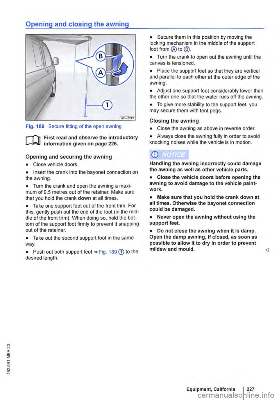
Fig. 189 Secure fitting of the open awning
r-1l1 First read and observe the introductory information given on page 226.
Opening and securing the awning
• Close vehicle doors.
• Insert the crank into the bayonet connection on the awning.
• Turn the crank and open the awning a maxi-mum of 0.5 metres out of the retainer. Make sure that you hold the crank down at all times.
• Take one support foot out of the front trim. For this, gently push out the end of the foot (in the mid-dle of the front trim). When doing so, hold the bot-tom of the support foot firmly to prevent it snapping out of the retainer.
• Take out the second support foot in the same way.
• Push out both support feet =>Fig. 189 G) to the desired length.
• Secure them in this position by moving the locking mechanism in the middle of the support foot from ®to@.
• Turn the crank to open out the awning until the canvas is tensioned.
• Place the support feet so that they are vertical and parallel to each other at the outer edge of the awning.
• Adjust one support foot considerably lower than the other one so that the water runs off the awning.
• To give more stability to the support feet, you may secure them with tent pegs.
Closing the awning
• Close the awning as above in reverse order.
• Always close the awning fully in order to avoid knocking noises while the vehicle is in motion.
CD
Handling the awning incorrectly could damage the awning as well as other vehicle parts.
• Close the vehicle doors before opening the awning to avoid damage to the vehicle paint-work.
• Make sure that you hold the crank down at all times. Otherwise the bayonet connection could be damaged.
• Never open the awning without using the support feet.
• Do not close the awning when it Is damp. Open the damp awning, if closed, as soon as possible to allow it to dry in order to prevent mildew and mould.
Page 228 of 486
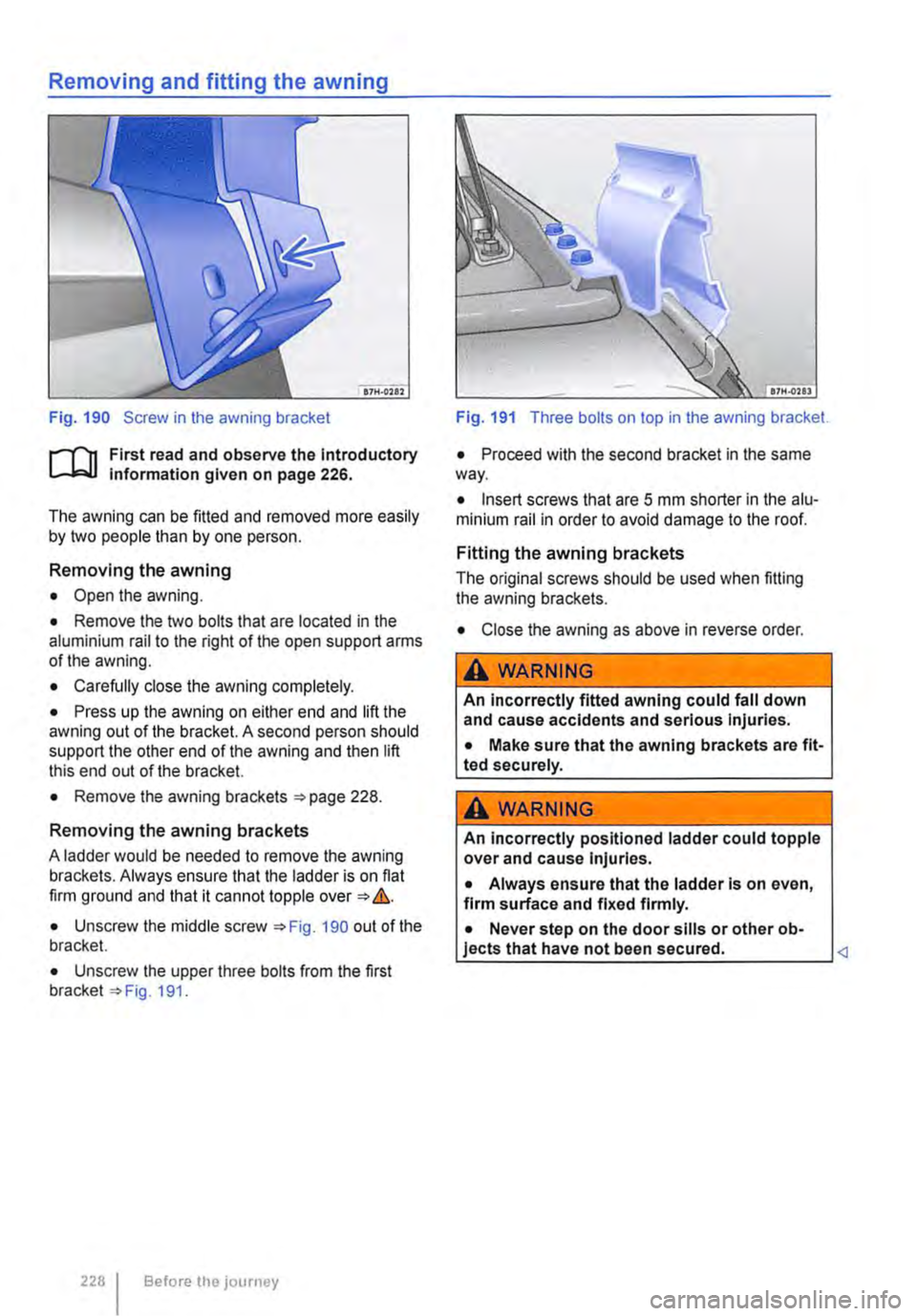
Fig. 190 Screw in the awning bracket
r--('n First read and observe the Introductory L-J.:.1.1 Information given on page 226.
The awning can be fitted and removed more easily by two people than by one person.
Removing the awning
• Open the awning.
• Remove the two bolts that are located in the aluminium rail to the right of the open support arms of the awning.
• Carefully close the awning completely.
• Press up the awning on either end and lift the awning out of the bracket. A second person should support the other end of the awning and then lift this end out of the bracket.
• Remove the awning brackets 228.
Removing the awning brackets
A ladder would be needed to remove the awning brackets. Always ensure that the ladder is on flat firm ground and that it cannot topple over &.
• Unscrew the middle screw 190 out of the bracket.
• Unscrew the upper three bolts from the first bracket 191.
228 I Before the journey
Fig. 191 Three bolts on top in the awning bracket.
• Proceed with the second bracket in the same way.
• Insert screws that are 5 mm shorter in the alu-minium rail in order to avoid damage to the roof.
Fitting the awning brackets
The original screws should be used when fitting the awning brackets.
• Close the awning as above in reverse order.
A WARNING
An incorrectly fitted awning could fall down and cause accidents and serious Injuries.
• Make sure that the awning brackets are fit-ted securely.
A WARNING
An incorrectly positioned ladder could topple over and cause Injuries.
• Always ensure that the ladder is on even, firm surface and fixed firmly.
• Never step on the door sills or other ob-jects that have not been secured.
Page 229 of 486
Tables and camping chairs, California
CllJ Introduction
This chapter contains information on the following subjects:
Folding table in the sliding door . . . . . . . . . . . . 229
Folding the work table out and in . . . . . . . . . . 230
Moving the work table . . . . . . . . . . . . . . . . . • . 231
Camping chairs . . . . . . . . . . . . . . . . . . . . . . . . 232 Flyscreen element for the sliding window . . . . 232
Additional Information and warnings:
• Seat functions, front 69
• Seat functions, rear =>page 72
• Stowage 150
• Stowage areas, California 210
• Drink holder 153
• Tailgate 36
• Awning 226
Folding table in the sliding door
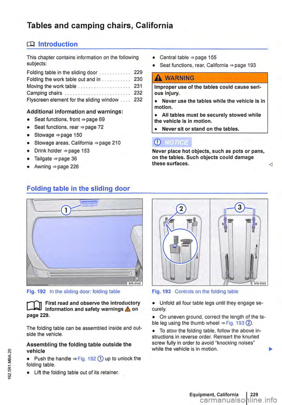
Fig. 192 in the sliding door: folding table
J"'"'"('n First read and observe the introductory L-Jo:.LI information and safety warnings & on page 229.
The folding table can be assembled inside and out-side the vehicle.
Assembling the folding table outside the vehicle
• Push the handle 192 G) up to unlock the folding table.
• Lift the folding table out of its retainer.
• Central table 155
• Seat functions, rear, California 193
,A WARNING
Improper use of the tables could cause seri-ous Injury.
• Never use the tables while the vehicle is in motion.
• All tables must be securely stowed while the vehicle is in motion.
• Never sit or stand on the tables.
CD
Never place hot objects, such as pots or pans, on the tables. Such objects could damage these surfaces.
I !! I
I
I
.. -17£.0161
Fig. 193 Controls on the folding table
• Unfold all four table legs until they engage se-curely.
• On uneven ground, correct the length of theta-ble leg using the thumb wheel 193 @.
• To stow the folding table, follow the above in-structions in reverse order. Reinsert the knurled screw fully in order to avoid "knocking noises" while the vehicle is in motion. .,.
Equipment, California 229
Page 230 of 486
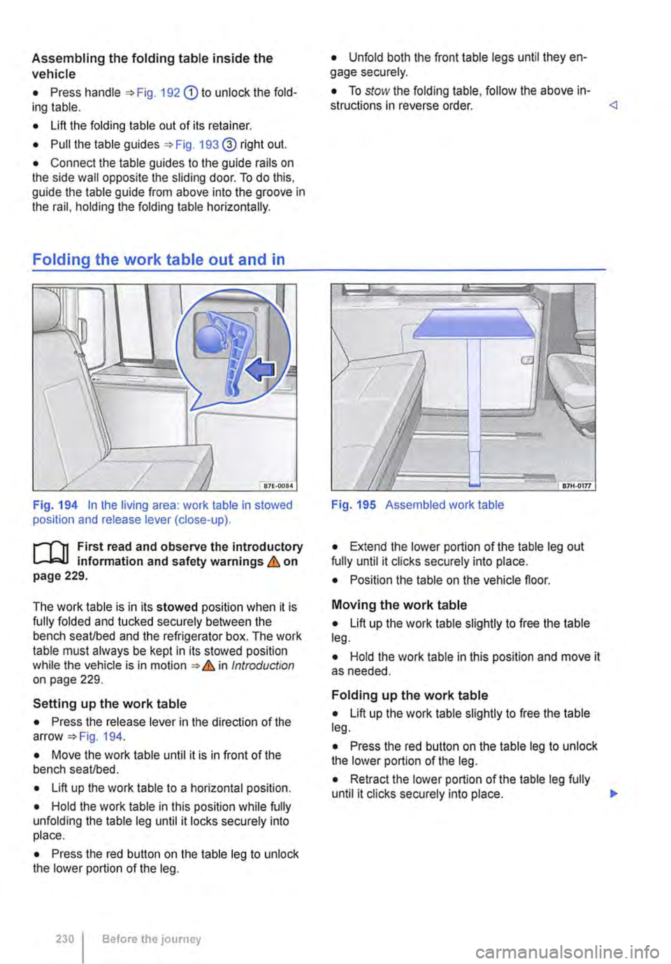
Assembling the folding table inside the vehicle
• Press handle 192 G) to unlock the fold-ing table.
• Lift the folding table out of its retainer.
• Pull the table guides 193@ right out.
• Connect the table guides to the guide rails on the side wall opposite the sliding door. To do this, guide the table guide from above into the groove in the rail, holding the folding table horizontally.
Fig. 194 In the living area: work table in stowed position and release lever (close-up).
1""1'11 First read and observe the introductory L-J,:.,U information and safety warnings & on page 229.
The work table is in its stowed position when it is fully folded and tucked securely between the bench seat/bed and the refrigerator box. The work table must always be kept in its stowed position while the vehicle is in motion & in Introduction on page 229.
Setting up the work table
• Press the release lever in the direction of the arrow 194.
• Move the work table until it is in front of the bench seat/bed.
• Lift up the work table to a horizontal position.
• Hold the work table in this position while fully unfolding the table leg until it locks securely into place.
• Press the red button on the table leg to unlock the lower portion of the leg.
230 Before the journey
• Unfold both the front table legs until they en-gage securely.
• To stow the folding table, follow the above in-structions in reverse order.
Fig. 195 Assembled work table
• Extend the lower portion of the table leg out fully until it clicks securely into place.
• Position the table on the vehicle floor.
Moving the work table
• Lift up the work table slightly to free the table leg.
• Hold the work table in this position and move it as needed.
Folding up the work table
• Lift up the work table slightly to free the table leg.
• Press the red button on the table leg to unlock the lower portion of the leg.
• Retract the lower portion of the table leg fully until it clicks securely into place. 11>