check engine VOLKSWAGEN TRANSPORTER 2013 Owner's Manual
[x] Cancel search | Manufacturer: VOLKSWAGEN, Model Year: 2013, Model line: TRANSPORTER, Model: VOLKSWAGEN TRANSPORTER 2013Pages: 486, PDF Size: 69.28 MB
Page 273 of 486
heavy load on the brakes should be avoided. For example, when driving too close to the vehicle ahead.
The rate of wear of the brake pads depends to a great extent on the conditions under which the ve-hicle is operated and the way in which the vehicle is driven. With regular urban trips, short journeys and a sporty driving style, the brake pads must be checked by a qualified workshop more regularly than stated in the service schedule.
When driving with wet brakes, for example after driving through water, after heavy rainfall or after washing the vehicle, the braking effect may be de-layed as the brake discs will be wet, or possibly ic-ed up (in winter). The brakes must be "dried" as quickly as possible by careful braking at higher speed. Ensure that no vehicle behind you or no other road user is put at risk as a result of this ac-
Any salt layer accumulating on the discs and pads will delay the braking effect and increase the braking distance. If the brakes on the vehicle have not been applied for a long time on roads that have been gritted with salt, the layer of salt must be re-duced through careful braking &.
Corrosion on the brake discs and dirt in the brake pads are facilitated through long periods of inactivi-ty, low mileage and low load levels. With inactivity or low use levels for the brake pads as well as cor-rosion, Volkswagen Commercial Vehicles recom-mends that the brake discs and brake pads be cleaned by braking strongly several times from high speed. Ensure that no vehicle behind you or no other road user is put at risk as a result of this
Fault in the brake system
A brake circuit may have failed if you have to re-duce speed and the vehicle does not brake as nor-mal (sudden increase in braking distance). This will be indicated by the warning lamp m and in some cases a text message. Go to the nearest qualified workshop immediately to have the fault corrected. Drive at low speed when doing this and anticipate much longer braking distances and an increase in the pressure required on the pedal.
Brake servo
The brake serve will only function when the engine is running and reinforces the pressure applied by the driver on the brake pedal.
If the brake serve is not functioning or the vehicle is being towed, the brake pedal will have to be de-pressed more forcefully as the braking distance will be increased due to the lack of assistance for the brake system &.
A WARNING
New brake pads will not have the optimal braking effect when first fitted.
• New brake pads cannot generate the full braking effect during the first 300 km and must first be run In. A reduced braking effect can be Increased by applying more pressure to the brake pedal.
• You must drive particularly carefully when driving with new brake pads In order to re-duce the risk of accidents, serious Injuries and loss of control of the vehicle.
• Never drive too close to other vehicles when running in new brake pads, and never create a driving situation that will place a heavy load on the brakes.
A WARNING
Overheated brakes reduce the braking effect and considerably Increase the braking dis-tance.
• When driving downhill the brakes are placed under particular strain and become hot very quickly.
• Before driving down a long, steep gradi-ent, reduce speed and change to a lower gear or move the selector lever to a lower position. This will make use of the engine braking ef-fect and relieve the load on the brakes.
• Non-standard or damaged front spoilers could restrict the airflow to the brakes and cause them to overheat.
A WARNING
Wet brakes or brakes coated with ice or road salt react more slowly and require longer braking distances.
• Carefully apply the brakes to test them.
• Always dry brakes and clean off any coat-Ing of Ice and salt with a few cautious appli-cations of the brake when visibility, weather, road and traffic conditions permit.
A WARNING
Driving without the brake servo can consider-ably Increase the braking distance and thus cause accidents and serious Injuries.
• Never allow the vehicle to roll if the engine Is switched off.
Starting the engine, changing gear and parking 273
Page 274 of 486
A WARNING (Continued)
• If the brake servo does not function or the vehicle is being towed, the brake pedal will have to be depressed more forcefully as the braking distance will be Increased due to the lack of assistance for the brake system.
CD
• Never let the brakes "rub" by applying light pressure to the brake when it is not necessary to brake. Continual pressure on the brake pedal will overheat the brakes. This can considerably reduce the brake effect, increase the braking distance and, In certain circumstances, cause the brake system to fail completely.
Brake support systems
r-f'n First read and observe the Introductory l..-Wl information and safety warnings&. on page 269.
The brake support systems ESC, ABS, BAS, TCS and EDL only function when the engine is running. They make a considerable contribution to active driving safety.
Electronic stability control (ESC)
The ESC helps to reduce the risk of skidding and to improve driving stability by braking individual wheels in certain driving situations. The ESC de-tects critical driving situations such as oversteer, understeer and wheelspin. The system helps to stabilise the vehicle through targeted application of the brakes or by reducing engine torque.
ESC has its limitations. lt is important to realise that ESC cannot overcome the laws of physics. ESC will not be able to assist in every situation faced by a driver. For example, ESC will not be able to assist every time that there is a sudden change in the road surface quality. If a section of dry road is suddenly covered with water, mud or snow, ESC will not be able to assist in the same manner as on a dry road. If the vehicle aquaplanes (drives on a layer of water rather than on the road surface), ESC will not be able to assist in steering the vehicle as the contact to the road surface has been interrupted and it is therefore no longer pos-sible to steer or brake the vehicle. When driving at speed through bends, particularly on stretches of road with many bends, the ESC will not always be able to process complicated driving situations as
2741 While dnvang
m If the front brake pads are tested, the rear L!..J brake pads should be tested at the same time. Regularly check the thickness of the brake pads through the openings in the rims or from the underside of the vehicle. If necessary, remove the wheels to carry out a comprehensive check. Volks-wagen Commercial Vehicles recommends using a Volkswagen Commercial Vehicles dealership for this purpose.
Always adapt your speed and driving style to suit visibility, weather, road and traffic conditions. ESC cannot defy the laws of motion, improve the availa-ble power output, or keep the vehicle on the road if insufficient care and attention on the part of the driver causes the vehicle to leave the road. In-stead, the ESC improves the chances of keeping the vehicle under control and, in extreme on-road driving situations, exploits the driver's steering in-put to keep the vehicle travelling in the desired di-rection. If the vehicle is driving at a speed that leads it to leave the road before the ESC can pro-vide any kind of support, the ESC will be unable to provide any assistance.
The ASS, BAS, TCS and EDL systems are integra-ted into the ESC. The ESC is always on. If the trac-tion achieved in certain situations is not sufficient, TCS can be switched off by pressing the ASR (TCS) button =>Fig. 224. Always ensure that ASR (TCS) is switched back on again once traction is sufficient.
Automatic Post-Collision Braking System
In the event of an accident, the Automatic Post-Collision Braking System can help the driver to re-duce the risk of skidding, and the danger of secon-dary collisions, through automatic braking.
Page 277 of 486
Brake fluid
B7E.02AO
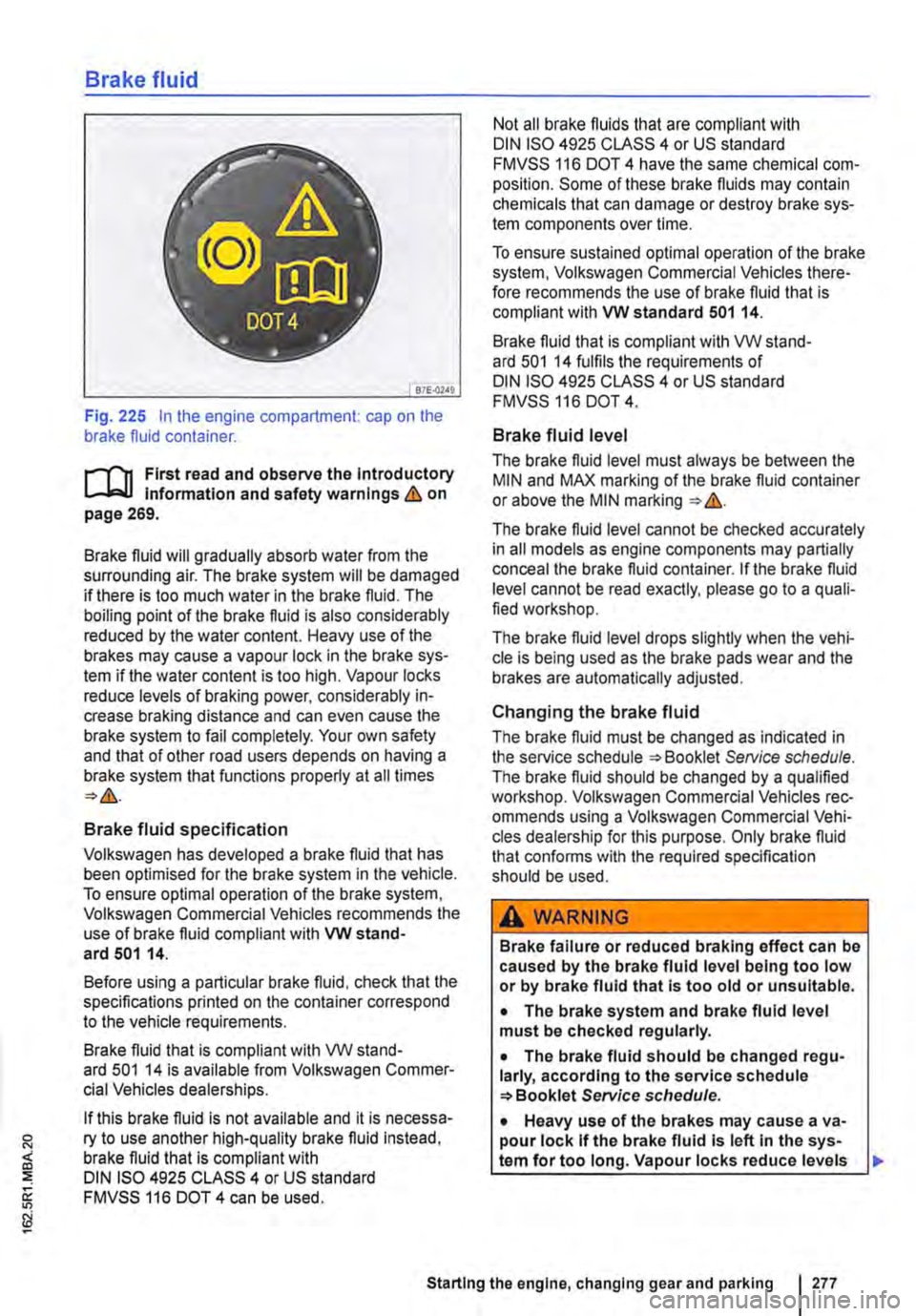
Fig. 225 In the engine compartment: cap on the brake fluid container.
r-111 First read and observe the Introductory l-Jr:,U Information and safety warnings&. on page 269.
Brake fluid will gradually absorb water from the surrounding air. The brake system will be damaged if there is too much water in the brake fluid. The boiling point of the brake fluid is also considerably reduced by the water content. Heavy use of the brakes may cause a vapour lock in the brake sys-tem if the water content is too high. Vapour locks reduce levels of braking power, considerably in-crease braking distance and can even cause the brake system to fail completely. Your own safety and that of other road users depends on having a brake system that functions properly at all times
Brake fluid specification
Volkswagen has developed a brake fluid that has been optimised for the brake system in the vehicle. To ensure optimal operation of the brake system, Volkswagen Commercial Vehicles recommends the use of brake fluid compliant with VW stand-ard 501 14.
Before using a particular brake fluid, check that the specifications printed on the container correspond to the vehicle requirements.
Brake fluid that is compliant with VW stand-ard 501 14 is available from Volkswagen Commer-cial Vehicles dealerships.
If this brake fluid is not available and it is necessa-ry to use another high-quality brake fluid instead, brake fluid that is compliant with DIN ISO 4925 CLASS 4 or US standard FMVSS 116 DOT 4 can be used.
Not all brake fluids that are compliant with DIN ISO 4925 CLASS 4 or US standard FMVSS 116 DOT 4 have the same chemical com-position. Some of these brake fluids may contain chemicals that can damage or destroy brake sys-tem components over time.
To ensure sustained optimal operation of the brake system, Volkswagen Commercial Vehicles there-fore recommends the use of brake fluid that is compliant with VW standard 501 14.
Brake fluid that is compliant with VW stand-ard 501 14 fulfils the requirements of DIN ISO 4925 CLASS 4 or US standard FMVSS 116 DOT 4.
Brake fluid level
The brake fluid level must always be between the MIN and MAX marking of the brake fluid container or above the MIN marking &.
The brake fluid level cannot be checked accurately in all models as engine components may partially conceal the brake fluid container. If the brake fluid level cannot be read exactly, please go to a quali-fied workshop.
The brake fluid level drops slightly when the vehi-cle is being used as the brake pads wear and the brakes are automatically adjusted.
Changing the brake fluid
The brake fluid must be changed as indicated in the service schedule Service schedule. The brake fluid should be changed by a qualified workshop. Volkswagen Commercial Vehicles rec-ommends using a Volkswagen Commercial Vehi-cles dealership for this purpose. Only brake fluid that confonns with the required specification should be used.
A WARNING
Brake failure or reduced braking effect can be caused by the brake fluid level being too low or by brake fluid that Is too old or unsuitable.
• The brake system and brake fluid level must be checked regularly.
• The brake fluid should be changed regu-larly, according to the service schedule Service schedule.
• Heavy use of the brakes may cause a va-pour lock If the brake fluid Is left In the sys-tem for too long. Vapour locks reduce levels
Starting the engine, changing gear and parking I 277
Page 282 of 486
Driver assist systems
Pull-away assist systems
cr:n Introduction
This chapter contains information on the following subjects:
Warning and indicator lamps . . . . . . . . . . . . . . 282
Start/stop system . . . . . . . . . . . . . . . . • . . . . . . . 283
Hill Hold Assist . . . . . . . . . . . . . . . . . . . . . . . . . . 284
Hill Descent Assist . . . . . . . . . . . . . . . . . . . . . . . 285
Rear axle differential lock . . . . . . . . . . . . . . . . . 286
Additional information and warnings:
• Volkswagen information system =>page 24
• Braking, stopping and parking =>page 269
• Battery =>page 362
• Wheels and tyres =>page 367
• Accessories, modifications, repairs and renewal of parts =>page 394
• Jump starting =>page 443
Warning and indicator lamps
A WARNING
The intelligent technology of the pull-away assist systems cannot overcome the laws of physics or system-related vehicle limitations. Never let the extra convenience afforded by pull-away assist systems tempt you into tak-ing any risks when driving-this can cause accidents.
• Unintentional vehicle movements can cause serious Injury.
• The pull-away assist systems cannot re-place the driver's full concentration.
• Always adapt your speed and driving style to suit visibility, weather, road and traffic con-ditions.
• Pull-away assist systems cannot hold the vehicle in all hill start situations or brake it sufficiently on all slopes going downhill (e.g. if the ground is slippery or icy).
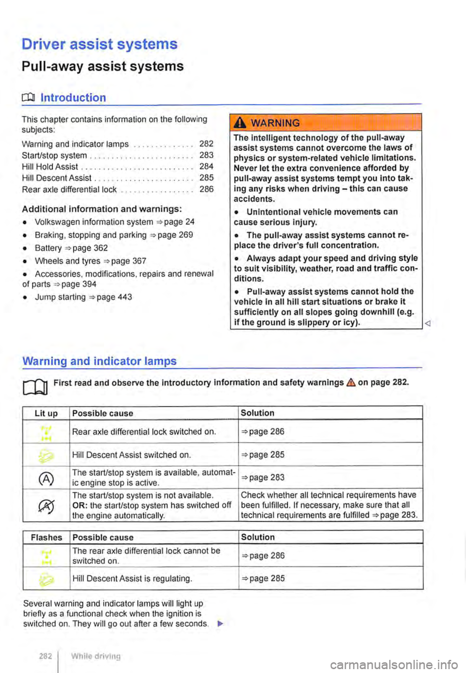
Lit up Possible cause
Rear axle differential lock switched on . ...
Hill Descent Assist switched on.
(A) The start/stop system is available, automat-ic engine stop is active.
ex;
The start/stop system is not available. OR: the start/stop system has switched off the engine automatically.
Flashes Possible cause
The rear axle differential lock cannot be .... switched on .
Hill Descent Assist is regulating.
Several warning and indicator lamps will light up briefly as a functional check when the ignition is switched on. They will go out after a few seconds. .,..
282 I While drivmg
Solution
=>page 286
=>page 285
=>page 283
Check whether all technical requirements have been fulfilled. If necessary, make sure that all technical requirements are fulfilled =>page 283.
Solution
=>page 286
=>page 285
Page 300 of 486
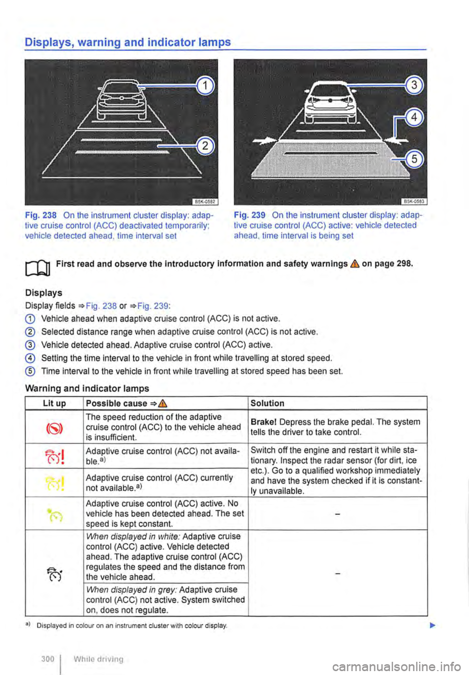
Fig. 238 On the instrument cluster display: adap-tive cruise control (ACC) deactivated temporarily; vehicle detected ahead, time interval set
Fig. 239 On the instrument cluster display: adap-tive cruise control (ACC) active: vehicle detected ahead. time interval is being set
ro First read and observe the Introductory Information and safety warnings & on page 298.
Displays
Display fields =>Fig. 238 or =>Fig. 239:
G) Vehicle ahead when adaptive cruise control (ACC) is not active.
® Selected distance range when adaptive cruise control (ACC) is not active.
@ Vehicle detected ahead. Adaptive cruise control (ACC) active.
@ Setting the time interval to the vehicle in front while travelling at stored speed.
® Time interval to the vehicle in front while travelling at stored speed has been set.
Warning and indicator lamps
Lit up Possible cause=>& Solution
The speed reduction of the adaptive Brakel Depress the brake pedal. The system cruise control (ACC) to the vehicle ahead is insufficient. tells the driver to take control.
fu! Adaptive cruise control (ACC) not availa-Switch off the engine and restart it while sta-ble.a) tionary. Inspect the radar sensor (for dirt, ice
Adaptive cruise control (ACC) currently etc.). Go to a qualified workshop immediately
"0! and have the system checked if it is constant-not available•) ly unavailable.
Adaptive cruise control (ACC) active. No .. (") vehicle has been detected ahead. The set -speed is kept constant.
1!\/hen displayed in white: Adaptive cruise control (ACC) active. Vehicle detected ahead. The adaptive cruise control (ACC)
fu
regulates the speed and the distance from the vehicle ahead. -
1!\/hen displayed in grey: Adaptive cruise control (ACC) not active. System switched on, does not regulate.
•> Displayed in colour on an instrument cluster with colour display.
300 I Whlio drivmg
Page 322 of 486
Air conditioning system
Heating, ventilating, cooling
o:n Introduction
This chapter contains information on the following subjects:
Controls for Climatic . . . . . . . . . . . . . . . . . . . . 323
Controls for Climatronic . . . . . . . . . . . . . . . . . 325
Controls for the heating and fresh air system . 327
Information on the air conditioning system . . . 328
..................... m
Air recirculation mode . . . . . . . • . . . . . . . . . . . . 330
Windscreen heating . . . . . . . . . . . . . . . . . . . . . 331
Roof ventilator . . . . . . . . . . . . . . . . . . . . . . . . . . 331
Displays for the Climatronic information
Depending on the vehicle equipment level, infor-mation on the Climatronic is displayed briefly on the screen of the factory-fitted radio or navigation system.
The dust and pollen filter
The dust and pollen filter with activated charcoal reduces the level of impurities in the outside air en-tering the vehicle.
The dust and pollen filler must be changed regular-ly to avoid impairing the performance of the air conditioning system.
The dust and pollen filter must be changed more frequently than stated in the service schedule if the efficiency of the filter declines prematurely due to the vehicle being used in areas with high levels of air pollution.
Additional information and warnings:
• Exterior views 5
• Wipers/washer 116
• Supplementary heaters (auxiliary air heater or auxiliary coolant heater) 332
• Cleaning and caring for the vehicle exterior 380
A WARNING
Poor visibility through all windows increases the risk of collisions and accidents, which can cause serious injuries.
• Always ensure that all windows are free of ice, snow and mist to ensure good visibility.
3221 While driving
A WARNING (Continued)
• Maximum heat output, which Is needed to defrost the windows as quickly as possible, is only available when the engine has reached Its operating temperature. Do not start your journey until you have good visibil-Ity.
• Always ensure that the heating and fresh air system or the air conditioning system and the rear window heating are used correctly so that you have good visibility.
• Never use the air reclrculatlon mode for an extended period. If the cooling system Is switched off, the windows can mist up very quickly In air reclrculatlon mode and reduce visibility considerably.
• Always switch off the air reclrculatlon mode when it Is not required.
A WARNING
Stale air can quickly make the driver tired and affect their concentration, which In turn can cause collisions, accidents and serious Inju-ries.
• Never switch off the blowers or switch on the air recirculatlon mode for an extended pe· riod as this prevents fresh air from entering the vehicle interior.
• Repairs to the air conditioning system re-quire specialist knowledge and special tools. Volkswagen Commercial Vehicles recommends using a Volkswagen Commercial Vehicles deal-ership for this purpose.
Page 328 of 486
Settings for optimal road visibility
• Switch off air recirculation mode 330.
• Set blower® to level 1 or 2.
• Set the temperature selector G) to the required position.
• Open and position all vents on the dash panel.
• Turn the air distribution Fig. 258 0 to the desired position.
Rear window heating
A button for the rear window heating @ may be contained in the dash panel.
• When the engine is running, press the @ but-ton to switch on the rear window heating.
• The rear window heating is switched off auto-matically after approx. 10 minutes. To switch it off before the automatic switch-off, press the(!) but-ton again.
A WARNING
Stale air can quickly make the driver tired and affect their concentration, which in turn can cause collisions, accidents and serious inju-ries.
• Never switch off the blowers or switch on the air recirculatlon mode for an extended pe-riod as this prevents fresh air from entering the vehicle Interior.
.........r'n First read and observe the Introductory L-.lr:.ll Information and safety warnings & on page 322.
The cooling system for the vehicle interior only works when the engine is running and the blower is switched on.
The air conditioning system operates most effec-tively with the windows and the sliding/tilting roof closed. However, if the vehicle has heated up after standing in the sun for some time, the air inside can be cooled more quickly by opening the win-dows and the sliding/tilting roof for a short time.
Settings for optimal road visibility
Switching the cooling system on not only reduces the temperature of the vehicle interior, but also the humidity. This improves comfort for the vehicle oc-cupants and prevents the windows from misting when the outside humidity is high.
Climatic
• Switch off air recirculation mode 330.
• Set the blowers to the required level.
• Set the temperature to +22•c (+72.F).
• Open and position all vents on the dash panel 329.
• Turn the air distribution controller to the desired position.
• Press the@) button to switch the cooling sys-tem on. The indicator lamp in the button lights up.
328 I While driving
Cllmatronlc
• Press button.
• Set the temperature to +22•c (+72.F).
• Open and position all vents on the dash panel 329.
The cooling system cannot be switched on
The following criteria may prevent the cooling sys-tem from being switched on:
• The engine is not running.
• The blower is switched off.
• The air conditioning system fuse has blown.
• The ambient temperature is lower than approxi-mately +3"C (+38°F).
• The compressor has been temporarily switched off because the coolant temperature is too high.
• There is a different fault in the vehicle. The air conditioning system should be checked by a quali-fied workshop.
Things to note
If the humidity and temperature outside the vehicle are high, condensation can drip off the evaporator in the cooling system and form a pool underneath the vehicle. This is normal and does not indicate a
Page 332 of 486
![VOLKSWAGEN TRANSPORTER 2013 Owners Manual Supplementary heaters (auxiliary air heater or auxiliary
coolant heater)
[Q] Introduction
This chapter contains information on the following subjects:
Controls . . . . . . . . . . . . . . . . . . VOLKSWAGEN TRANSPORTER 2013 Owners Manual Supplementary heaters (auxiliary air heater or auxiliary
coolant heater)
[Q] Introduction
This chapter contains information on the following subjects:
Controls . . . . . . . . . . . . . . . . . .](/img/18/55784/w960_55784-331.png)
Supplementary heaters (auxiliary air heater or auxiliary
coolant heater)
[Q] Introduction
This chapter contains information on the following subjects:
Controls . . . . . . . . . . . . . . . . . . . . . . . . . . . . . . . 333
Switching the supplementary heating system on and off . . . . . . . . . . . . . . . . . . . . . . . . 334
Remote control . . . . . . . . . . . . . . . . . 335
Programming the supplementary heating system . . . . . . . . . . . . . . . . . . . . . . 338 Switching the child proof lock on and off . . . . . 339
Operation . . . . . . . . . . . . . . . . . . . . . . . . 339
The supplementary heating system is supplied with fuel from the vehicle fuel tank and can be used when the vehicle is in motion or stationary. Electri-cal power is supplied by the vehicle battery.
The auxiliary air heater runs in air recirculation mode and heats the vehicle interior. it has sepa-rate vents in the passenger compartment =>Fig. 265.
The auxiliary coolant heater heats the heating circuit. Heat is guided into the vehicle interior via the vents for the heating or air conditioning system. With the auxiliary coolant heater, it is possible to switch between heating and ventilating.
Additional information and warnings:
• Supplementary heater in the California =>page 192
• Filling the tank =>page 340
• Battery =>page 362
Swallowing batteries with a diameter of 20 mm or other lithium batteries can result in severe or even fatal injuries within a very short period of time.
• Always keep the vehicle key, key ring with batteries, spare batteries, round cells and other batteries that are larger than 20 mm out of the reach of children.
332 I While driving
• Call for medical help immediately you pect that someone has swallowed a batte
A WARNING
The fumes from the supplementary heating system contain carbon monoxide, which is an odourless and colourless poisonous gas. Carbon monoxide can cause people to lose consciousness. lt can also cause death.
• Never start or run the supplementary heat-ing system In unventllated or closed rooms.
• Never program the supplementary heating system so that Is switched on and run In un-ventilated or enclosed areas.
A WARNING
Parts of the exhaust system of the supple-mentary heating system become very hot. This can cause fires.
• Park the vehicle so that no part of the ex-haust system can come Into contact with any Inflammable material underneath the vehicle, e.g. dry grass.
Q)
Do not place any food, medicine or any other temperature-sensitive items in front of the vents. Heat-sensitive food, medicine and other items could be either damaged or rendered useless.
m After starting the engine with a discharged W vehicle battery, or after the battery has been changed, system settings (time, date, personal convenience settings and programming) may have been changed or deleted. Check and correct the settings as necessary once the vehicle battery has been sufficiently charged.
Page 340 of 486
At the filling station
Filling the tank
o:n Introduction
This chapter contains information on the following subjects:
Indicator lamps and fuel gauge . . . . . . . . . . . . 341
Filling the tank with petrol or diesel . . . . . . . . . 342
Capacities . . . . . . . . . . . 343
Checks when filling the tank . . . . . . . . . . . . . . . 343
The fuel cap is located at the left-hand side of the vehicle.
Additional information and warnings:
• Exterior views 5
• Fuel 343
• Preparation for working in the engine ccmpart-ment page 350
A WARNING
Filling the tank incorrectly and incorrect han-dling of fuel can cause explosions, fire, seri-ous burns and other injuries.
• Always ensure that the tank cap is proper-ly closed, to prevent the evaporation and spillage of fuel.
• Fuel is highly explosive and inflammable and can cause serious burns and other inju-ries.
• Fuel can spill out if the engine is not switched off or the filler nozzle is not fully in-serted into the fuel filler neck when filling the tank. This could cause fire, explosions, seri-ous burns and other Injuries.
• When refilling with fuel, the engine , sup-plementary heating system(=> page 332) and the ignition must be switched off for security reasons.
• When filling the tank, always switch off your mobile telephone and two-way radio or any other radio equipment. Electromagnetic radiation can generate sparks which can in turn start a fire.
• Never get back into the vehicle while fill-ing the tank. If in exceptional cases you have to enter the vehicle, close the door and touch a metal object before touching the filler noz-zle again. This will remove any electrostatic
340 I While driving
A WARNING (Continued)
charge from you. Failure to do so could gen-erate a spark. Sparks can cause a fire when filling the tank.
• Never refuel or fill a spare canister near open flames, sparks or smouldering Items, e.g. cigarettes.
• Electrostatic discharge and electromag-netic radiation must be avoided when filling the tank.
• Follow all applicable safety information provided by the filling station when filling the tank.
• Never spill fuel in the vehicle or In the lug-gage compartment
A WARNING
For safety reasons, Volkswagen Commercial Vehicles does not recommend carrying a spare fuel canister In the vehicle. Fuel can spill out of the full or empty canister and catch fire, especially In the event of an acci-dent. This could cause explosions, fire and injuries.
• If, In exceptional circumstances, you have to transport a spare fuel canister, please note the following:
-When refilling never place the canister In or on top of the vehicle, for example In the luggage compartment or on the tall-gate. There may be an electrostatic charge during refilling causing the fuel fumes to Ignite.
-Always place the spare fuel canister on the ground.
-When filling a spare fuel canister, place the filler nozzle as far as possible Into the filler opening.
-If the spare fuel canister Is made of met-al, the filler nozzle must have constant contact with the canister In order to avoid static charging.
-Please follow all legislation concerning the use, stowage and transport of a spare fuel canister.
Page 341 of 486
A WARNING (Continued)
CD
-Please ensure that the spare fuel can is· ter corresponds with the Industry stand· ard, for example AN SI or ASTM F852-86.
• Remove split fuel from all vehicle compo· nents as quickly as possible In order to avoid damage to the wheel housing, tyres and vehicle paint.
• • Filling up with petrol in a vehicle fitted with a diesel engine or refilling with diesel in vehicle equipped with a petrol engine can cause seri· ous ands expensive engine damage and dam· age to the fuel system that is not covered by
Indicator lamps and fuel gauge
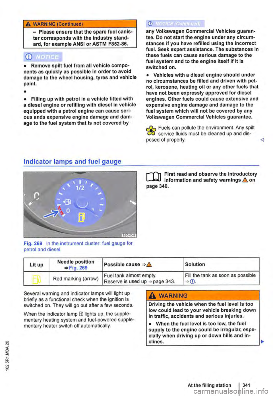
Fig. 269 In the instrument cluster: fuel gauge for petrol and diesel.
CD
any Volkswagen Commercial Vehicles guaran· tee. Do not start the engine under any circum-stances if you have refilled using the Incorrect fuel. Seek expert assistance. The substances In these fuels can cause serious damage to the fuel system and to the engine itself if it Is switched on.
• Vehicles with a diesel engine should under no circumstances be filled and driven with pet· rol, kerosene, heating oil or any other fuels that have not been expressly approved for diesel engines. Other fuels could cause extensive and expensive engine damage and damage to the fuel system which will not be covered by any Volkswagen Commercial Vehicles guarantee.
r.:Gh Fuels can pollute the environment. Any spilt W service fluids must be cleaned up and dis· posed of properly.
Lit up Needle position Possible cause & Solution 269
b Red marking (arrow) Fuel tank almost empty. Fill the tank as soon as possible Reserve is used up 343.
Several warning and indicator lamps will light up briefly as a functional check when the ignition is switched on. They will go out after a few seconds.
When the Indicator lamp Blllghts up, the supple-mentary heating system and fuel-powered supple-mentary heater switch off automatically.
A WARNING
Driving the vehicle when the fuel level is too low could lead to your vehicle breaking down In traffic, accidents and serious injuries.
• When the fuel level is too low, the fuel supply to the engine could be Irregular, espe-cially when driving up or down hills and in-clines. .,..
At the filling station 341