check engine VOLKSWAGEN TRANSPORTER 2013 User Guide
[x] Cancel search | Manufacturer: VOLKSWAGEN, Model Year: 2013, Model line: TRANSPORTER, Model: VOLKSWAGEN TRANSPORTER 2013Pages: 486, PDF Size: 69.28 MB
Page 206 of 486
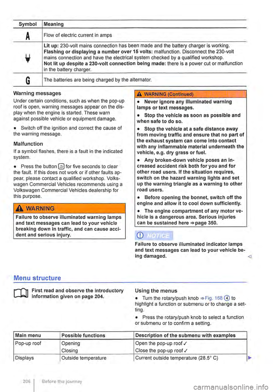
Symbol Meaning
A Flow of electric current in amps
Lit up: 230-volt mains connection has been made and the battery charger is working. Flashing or displaying a number over 15 volts: malfunction. Disconnect the 230-volt mains connection and have the electrical system checked by a qualified workshop. Not lit up despite a 230-volt connection being made: there is a power cut or malfunction in the battery charger.
G The batteries are being charged by the alternator.
Warning messages
Under certain conditions, such as when the pop-up roof is open, warning messages appear on the dis-play when the engine is started. These warn against possible vehicle or equipment damage.
• Switch off the ignition and correct the cause of the warning message.
Malfunction
If a symbol flashes, there is a fault in the indicated system.
• Press the button G?) for five seconds to clear the fault. If this does not work or if other faults ap-pear, please contact a qualified workshop. Volks-wagen Commercial Vehicles recommends using a Volkswagen Commercial Vehicles dealership for this purpose.
A WARNING
Failure to observe illuminated warning lamps and text messages can lead to your vehicle breaking down in traffic, and can cause acci-dent and serious injury.
A WARNING (Continued)
• Never Ignore any Illuminated warning lamps or text messages.
• Stop the vehicle as soon as possible and when safe to do so.
• Stop the vehicle at a safe distance away from moving traffic and ensure that no part of the exhaust system can come Into contact with any Inflammable material underneath the vehicle, e.g. dry grass or fuel.
• Any broken-down vehicle poses an In-creased accident risk both for you and for other road users. If the situation requires, switch on the hazard warning lights and set up the warning triangle as a warning to other road users.
• Before opening the bonnet, switch off the engine and allow it to cool down sufficiently.
• The engine compartment of any motor ve-hicle is a dangerous area. Serious injuries can be sustained here 350.
CD
Failure to observe illuminated indicator lamps and text messages can lead to your vehicle be-ing damaged.
J'"'""'('n First read and observe the introductory L-J,:.IJ information given on page 204.
Main menu Possible functions
Pop-up roof Opening
Closing
Displays Outside temperature
206 Before the journey
Using the menus
• Turn the rotary/push knob 168@ to highlight a function or submenu or to change a set-ting.
• Press the rotary/push knob to select a function or submenu or to confirm a setting.
Description of the submenu with examples
Open the pop-up roof .,1
Close the pop-up roof .,t
Current outside temperature (28.SO C) ...
Page 223 of 486
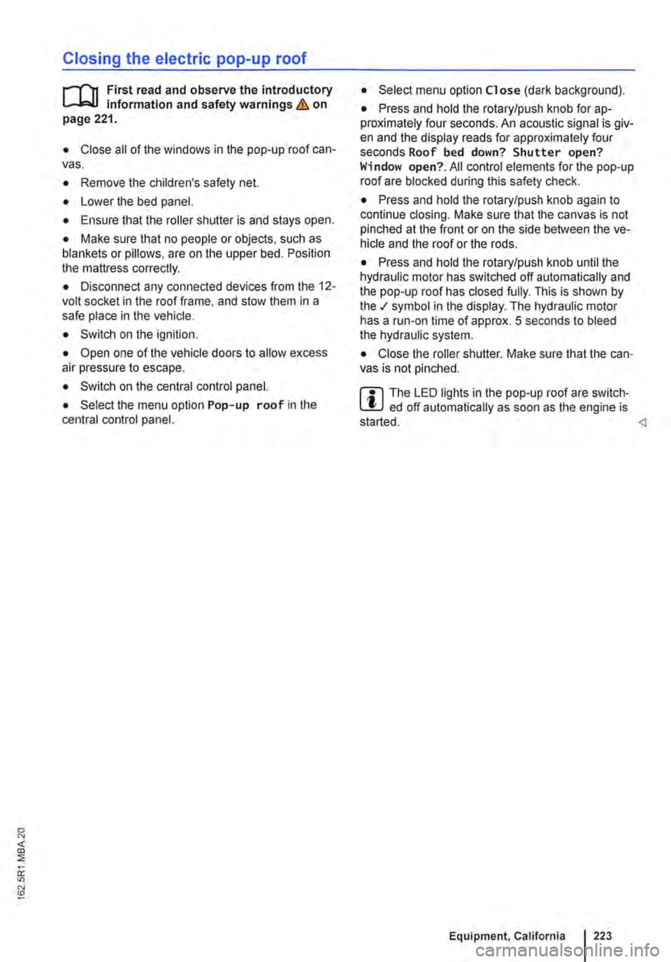
Closing the electric pop-up roof
j'"'('n First read and observe the introductory information and safety warnings & on page 221.
• Close all of the windows in the pop-up roof can-vas.
• Remove the children's safety net.
• Lower the bed panel.
• Ensure that the roller shutter is and stays open.
• Make sure that no people or objects, such as blankets or pillows, are on the upper bed. Position the mattress correctly.
• Disconnect any connected devices from the 12-volt socket in the roof frame, and stow them in a safe place in the vehicle.
• Switch on the ignition.
• Open one of the vehicle doors to allow excess air pressure to escape.
• Switch on the central control panel.
• Select the menu option Pop-up roof in the central control panel.
• Select menu option Close (dark background).
• Press and hold the rotary/push knob for ap-proximately four seconds. An acoustic signal is giv-en and the display reads for approximately four seconds Roof bed down? Shutter open? Window open?. All control elements for the pop-up roof are blocked during this safety check.
• Press and hold the rotary/push knob again to continue closing. Make sure that the canvas is not pinched at the front or on the side between the ve-hicle and the roof or the rods.
• Press and hold the rotary/push knob until the hydraulic motor has switched off automatically and the pop-up roof has closed fully. This is shown by the .t symbol in the display. The hydraulic motor has a run-on time of approx. 5 seconds to bleed the hydraulic system.
• Close the roller shutter. Make sure that the can-vas is not pinched.
m The LED lights in the pop-up roof are switch-L!..J ed off automatically as soon as the engine is
Equipment, California I 223
Page 254 of 486
Cleaning the cooker and sink
Clean the surfaces of the gas cooker and sink with commercially available non-abrasive cleaning Remove the pan supports from atop the burners to clean the surface of the gas cooker.
When cleaning the gas cooker, make sure that you do not damage or bend the heat sensors on the burners.
The gas burners should be cleaned with a brush at regular intervals.
CD
Abrasive sponges and cleaning agents can scratch and otherwise damage surfaces.
CD
Cleaning products that contain solvents, e.g. acetone, paint thinner, attack the material and can cause damage. <1
Cleaning the display of the central control panel
CD r-l'n First read and observe the Introductory L-l.::JJ information given on page 252. Do not use solvents such as turpentine or pet-
When cleaning the display, use an anti-static cloth or anti-static agent in order to prevent the build up of static charge on the display, which could render the display symbols unrecognizable
rol to clean the display, as these will damage lt.
[]J First read and observe the introductory information given on page 252.
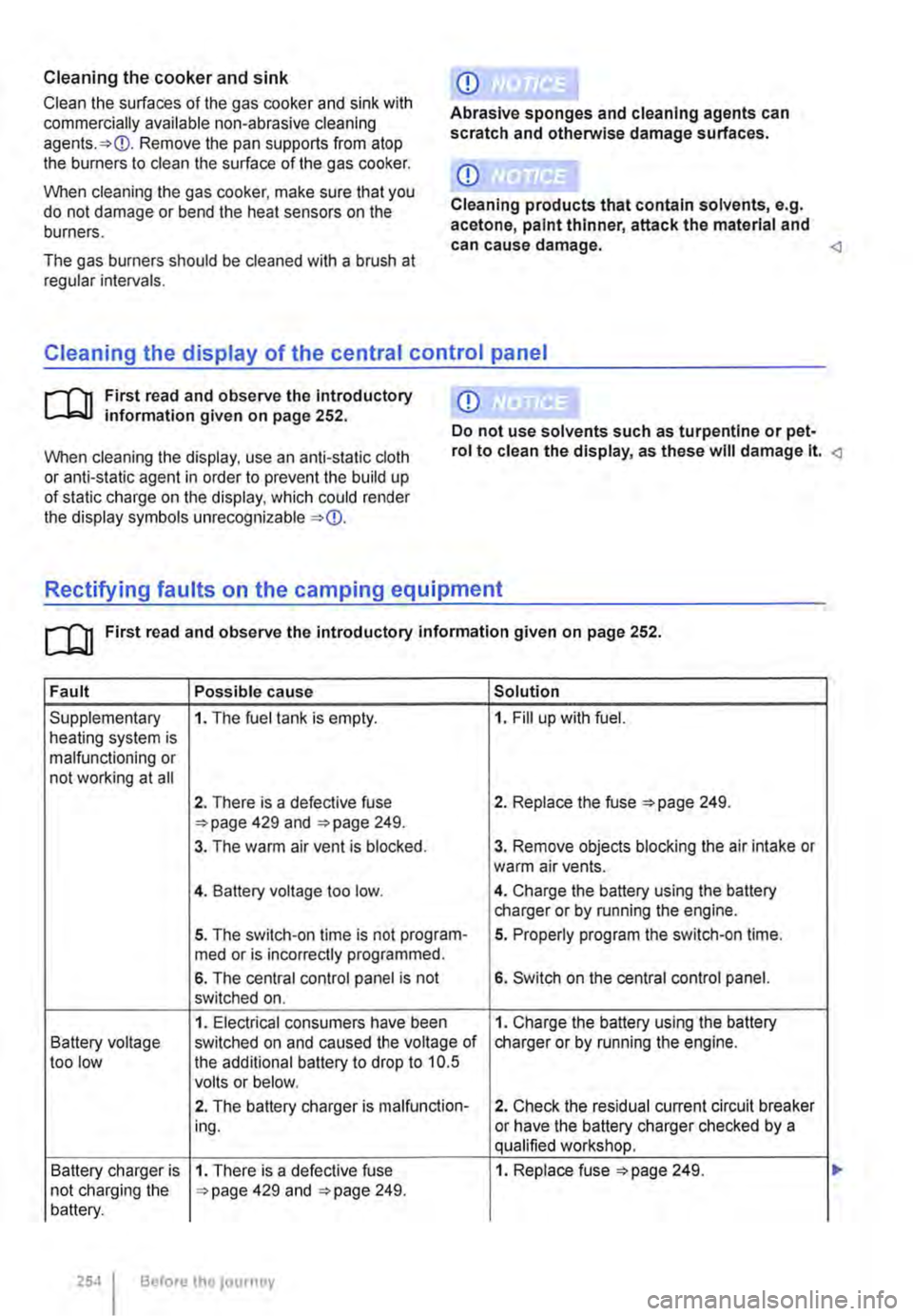
Fault Possible cause Solution
Supplementary 1. The fuel tank is empty. 1. Fill up with fuel. heating system is malfunctioning or not working at all
2. There is a defective fuse 2. Replace the fuse 249. 429 and 249.
3. The warm air vent is blocked. 3. Remove objects blocking the air intake or warm air vents.
4. Battery voltage too low. 4. Charge the battery using the battery charger or by running the engine.
5. The switch-on time is not program-5. Properly program the switch-on time. med or is incorrectly programmed.
6. The central control panel is not 6. Switch on the central control panel. switched on.
1. Electrical consumers have been 1. Charge the battery using the battery Battery voltage switched on and caused the voltage of charger or by running the engine. too low the additional battery to drop to 10.5 volts or below.
2. The battery charger is malfunction-2. Check the residual current circuit breaker ing. or have the battery charger checked by a qualified workshop.
Battery charger is 1. There is a defective fuse 1. Replace fuse =>page 249. not charging the 429 and 249. battery.
254 Before the journey
Page 255 of 486
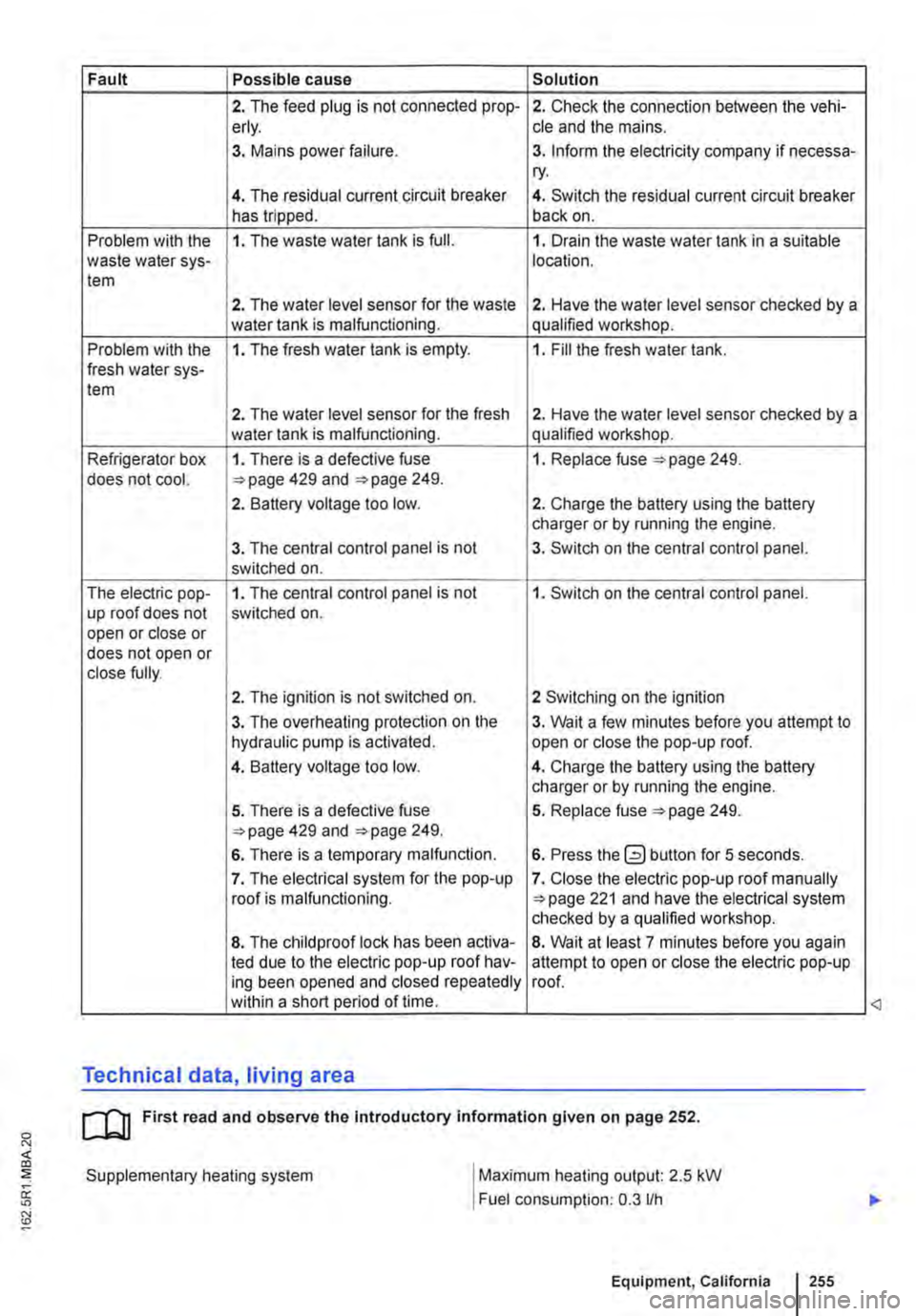
Fault Possible cause Solution
2. The feed plug is not connected prop-2. Check the connection between the vehi-erly. cle and the mains.
3. Mains power failure. 3. Inform the electricity company if necessa-ry.
4. The residual current circuit breaker 4. Switch the residual current circuit breaker has tripped. back on.
Problem with the 1. The waste water tank is full. 1. Drain the waste water tank in a suitable waste water sys-location. tem
2. The water level sensor for the waste 2. Have the water level sensor checked by a water tank is malfunctioning. qualified workshop.
Problem with the 1. The fresh water tank is empty. 1. Fill the fresh water tank. fresh water sys-tem
2. The water level sensor for the fresh 2. Have the water level sensor checked by a water tank is malfunctioning. qualified workshop.
Refrigerator box 1. There is a defective fuse 1. Replace fuse 249. does not cool. 429 and 249.
2. Battery voltage too low. 2. Charge the battery using the battery charger or by running the engine.
3. The central control panel is not 3. Switch on the central control panel. switched on.
The electric pop-1. The central control panel is not 1. Switch on the central control panel. up roof does not switched on. open or close or does not open or close fully.
2. The ignition is not switched on. 2 Switching on the ignition
3. The overheating protection on the 3. Wait a few minutes before you attempt to hydraulic pump is activated. open or close the pop-up roof.
4. Battery voltage too low. 4. Charge the battery using the battery charger or by running the engine.
5. There is a defective fuse 5. Replace fuse 249. 429 and 249.
6. There is a temporary malfunction. 6. Press the button for 5 seconds.
7. The electrical system for the pop-up 7. Close the electric pop-up roof manually roof is malfunctioning. 221 and have the electrical system checked by a qualified workshop.
8. The child proof lock has been activa-8. Wait at least 7 minutes before you again led due to the electric pop-up roof hav-attempt to open or close the electric pop-up ing been opened and closed repeatedly roof. within a short period of time.
Technical data, living area
cu First read and observe the Introductory information given on page 252.
Supplementary heating system
I
Maximum heating output: 2.5 kW
Fuel consumption: 0.3 lfh
Equipment, California I 255
<3
Page 262 of 486
Flashes Possible cause Solution
The lock button in the selector lever is not Engage the selector lever lock 265. engaged. The vehicle cannot drive off.
Dual clutch gearbox DSG®. Drive to the nearest qualified workshop immedi-
/ ./ flashes alternately with selector lever dis-ately at a low engine speed to have the system play, e.g. D.
Several warning and indicator lamps will light up briefly as a functional check when the ignition is switched on. They will go out after a few seconds.
A WARNING
Failure to observe illuminated warning lamps and text messages can lead to your vehicle breaking down in traffic, and can cause acci-dent and serious injury.
• Never ignore any illuminated warning lamps or text messages.
Pedals
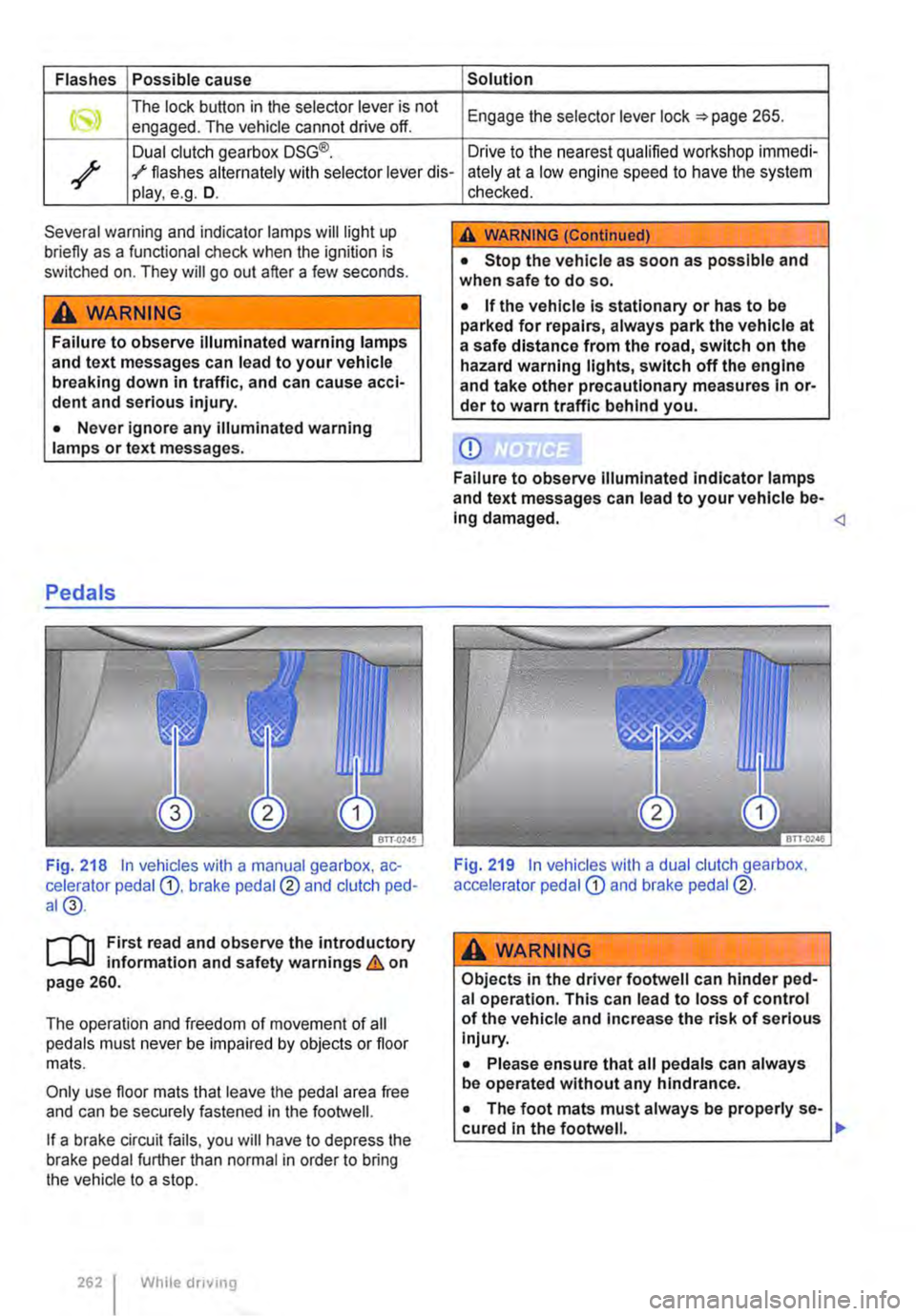
Fig. 218 In vehicles with a manual gearbox, ac-celerator pedal G), brake pedal@ and clutch ped-al@.
r-T'n First read and observe the introductory L-Wl information and safety warnings & on page 260.
The operation and freedom of movement of all pedals must never be impaired by objects or floor mats.
Only use floor mats that leave the pedal area free and can be securely fastened in the footwell.
If a brake circuit fails, you will have to depress the brake pedal further than normal in order to bring the vehicle to a stop.
262 I While driving
checked.
A WARNING (Continued)
• Stop the vehicle as soon as possible and when safe to do so.
• If the vehicle is stationary or has to be parked for repairs, always park the vehicle at a safe distance from the road, switch on the hazard warning lights, switch off the engine and take other precautionary measures In or-der to warn traffic behind you.
CD
Failure to observe Illuminated indicator lamps and text messages can lead to your vehicle be-Ing damaged.
A wARNING
Objects in the driver footwell can hinder ped-al operation. This can lead to loss of control of the vehicle and increase the risk of serious Injury.
• Please ensure that all pedals can always be operated without any hindrance.
• The foot mats must always be properly se-cured in the footwell. .,.
Page 264 of 486
Dual clutch gearbox DSG®
r-('n First read and observe the Introductory L-.lo:on Information and safety warnings & on page 260.
Description
The DSG® dual clutch gearbox is a gearbox which uses dual-clutch technology to change gear automatically. it uses a dual clutch and two independent gearboxes to enable very fast gear changes with no loss of torque. The DSG® dual clutch gearbox thus combines the performance and economy of a manual gearbox with the com-fort and convenience of a conventional automatic transmission.
How the system works
Engine power is transferred to the drive shafts via the gearbox. In order to change gears, the power transmission between the engine and the gearbox has to be interrupted. This is what the clutch is for.
With the DSG® dual clutch system with its two complementary gearboxes, one gearbox is always connected under load to the engine. When one gear is engaged, another gear is always preselec-
led in the other gearbox. The clutch on the non-driven gear is closed and the other is opened at the same time. This is what makes very fast gear changes possible.
The DSG® dual clutch gearbox is designed to be more efficient than an automatic gearbox. In an au-tomatic gearbox, the torque converter is constantly in use, whereas in the DSG® dual clutch system the idle clutch can be opened, thus saving fuel. With its efficiency, low weight and intelligent control system, the DSG® dual clutch system usually ena-bles fuel consumption equal to or lower than a manual gearbox.
like the manual gearbox, the clutch in the DSG dual clutch system is subject to wear. Regular maintenance is necessary, varying accord-ing to what type of DSG® dual clutch system is in-stalled. For more information see the service schedule. In the DSG® dual clutch system, if one gearbox malfunctions it is deactivated and the oth-er gearbox functions alone *page 267. If this happens, have the system checked as soon as possible by a qualified workshop.
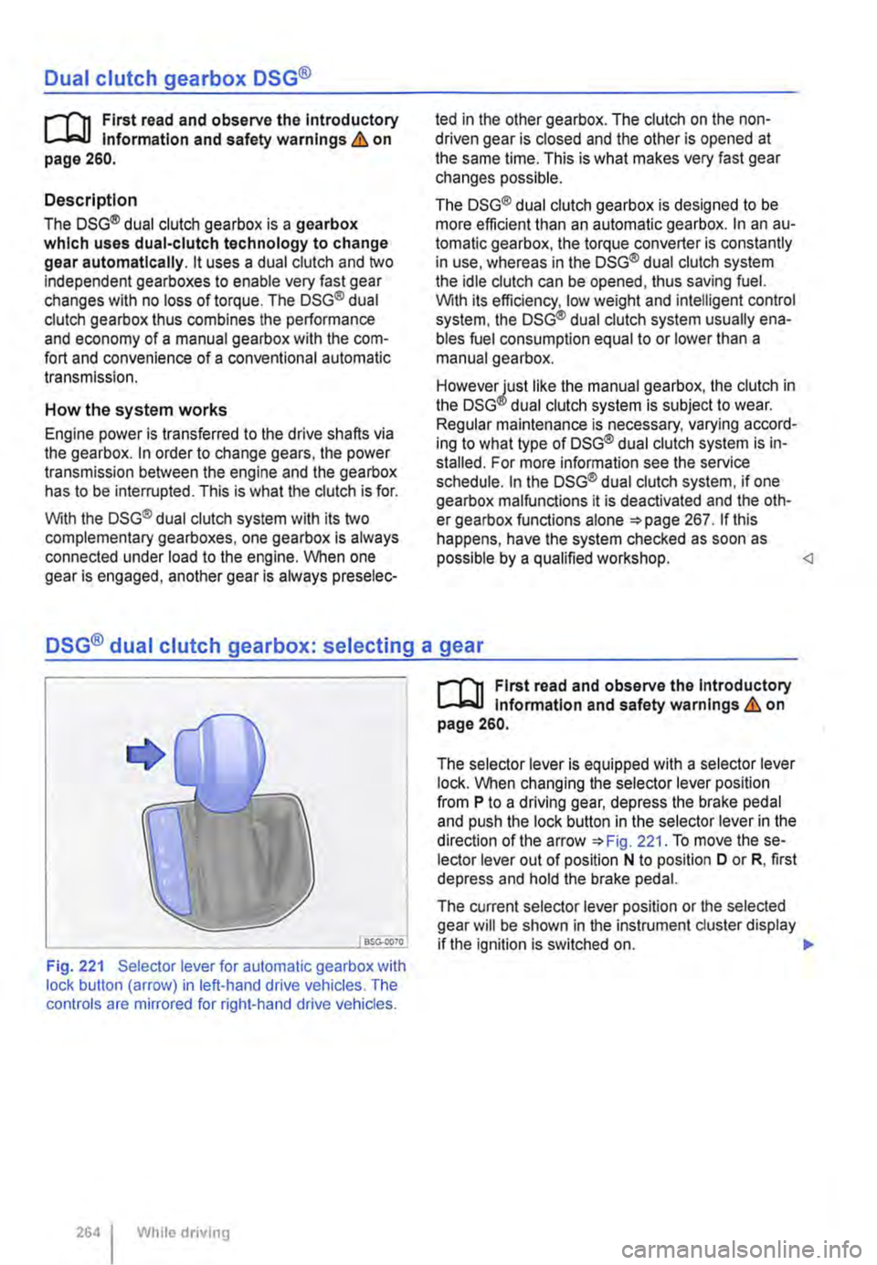
Fig. 221 Selector lever for automatic gearbox with lock button (arrow) in left-hand drive vehicles. The controls are mirrored for right-hand drive vehicles.
264 I While driving
r-('n First read and observe the Introductory L-.lo:on Information and safety warnings & on page 260.
The selector lever is equipped with a selector lever lock. When changing the selector lever position from P to a driving gear, depress the brake pedal and push the lock button in the selector lever in the direction of the arrow *Fig. 221. To move the se-lector lever out of position N to position D or R, first depress and hold the brake pedal.
The current selector lever position or the selected gear will be shown in the instrument duster display if the ignition is switched on. .,..
Page 267 of 486
• Reduce your speed.
• Push the selector lever from position D to the right into the Tiptronic gate 266.
• Gently push the selector lever to the rear to change down gear.
Stopping the vehicle and pulling away when driving uphill
The steeper the incline, the lower the gear that is required.
If you wish to stop the vehicle or pull away when driving uphill, you should use the Hill Hold Assist function 282.
Vehicles without Hill Hold Assist: when the vehi-cle is stopped on an incline and remains in gear, the vehicle must always be prevented from rolling by depressing the brake pedal or by applying the handbrake. The brake pedal or the handbrake should not be released until you start to pull away
Kickdown
The kickdown mechanism enables maximum ac-celeration in the selector lever positions D and S, or in the Tiptronic position.
If the accelerator pedal is depressed fully, the gear-box will automatically shift to a lower gear, depend-ing on the speed and engine revs. This will make use of the full vehicle acceleration &.
The gearbox does not shift up to the next gear until the engine reaches the maximum engine speed for the gear.
Freewheel driving with 7-speed dual clutch gearbox DSG®
In coasting mode, the momentum of the vehicle can be used to save fuel in conjunction with a fore-sighted driving style. The engine is declutched and no longer brakes the vehicle -the vehicle can roll out over a longer distance.
Switch-on condition: the selector lever must be in position D.
Fault in the DSG® dual clutch gearbox
r-f"'n First read and observe the introductory l-J::,JJ information and safety warnings & on page 260.
Emergency programme
There is a fault in the system if all the displays on the instrument cluster for the selector lever posi-tions have a light background. The automatic gear-
Triggering coasting
• Remove foot from accelerator pedal. The en-gine will be disengaged and run in freewheel mode. The vehicle rolls without the braking effect of the engine.
Cancelling coasting mode
• Depress the brake pedal briefly.
Coasting can be switched on and off in the Set-tings menu of the Volkswagen Information sys-tem 24.
A WARNING
Rapid acceleration can cause loss of traction and skidding, particularly on slippery roads. This can cause you to lose control of the ve-hicle, which can lead to accidents and seri-ous injuries.
• Always adjust your driving style in ac-cordance with the flow of traffic.
• Only use kickdown or fast acceleration if visibility, weather, road and traffic conditions permit, and other road users are not put at risk due to the acceleration and the driving style.
• You should never endanger other road users through the acceleration of your vehi-cle or through your driving style.
CD
• If you stop the vehicle on an incline, do not attempt to stop it from rolling back by depress-Ing the accelerator while a position is still se-lected. The automatic gearbox could overheat and be damaged.
• Never allow the vehicle to roll in position N, particularly if the ignition is switched off. The automatic gearbox will not be lubricated and could be damaged. <1
box is running in an emergency programme. The vehicle can still be driven in the emergency pro-gramme, but only at reduced speed and not in all gears.
In vehicles with a DSG® dual clutch gearbox, you may no longer be able to select reverse gear. The gearbox should be checked by a qualified workshop as soon as possible. .,..
Starting the engine, changing gear and parking 267
Page 268 of 486
In all cases the automatic gearbox should be checked by a qualified workshop Immediately.
Overheating of the DSG® dual clutch gearbox
The dual clutch gearbox can overheat when the vehicle pulls off regularly, travels at a crawl for long periods, or in stop and go traffic. Gearbox over-heating is indicated by the warning lamp (j) and in some cases by a text message in the instrument cluster display. A signal tone may also be given. Stop the vehicle and allow the gearbox to cool down
The vehicle will not move forwards or backwards even though a gear has been selected
If the vehicle will not move in the required direc-tion, the system may have selected the position in-correctly. Depress the brake pedal and reselect the position.
Gear-change indicator
r--f"'n First read and observe the Introductory L-lo:.l.l information and safety warnings & on page 260.
Depending on the vehicle equipment level, the in-strument cluster may indicate the gear which you should select in order to reduce fuel consumption while the vehicle is in motion.
Display Meaning
• The current gear is optimal.
f A higher gear is recommended.
! A lower gear is recommended.
In vehicles with a manual gearbox the recommen-ded gear will be indicated in the form of a number and a recommendation to shift up or down into the recommended gear will be displayed in the form of an arrow 263.
In vehicles with a OSG® dual clutch gearbox if the selector lever is in the Tiptronic position, the cur-rent gear will be indicated in the form of a number and a recommendation to shift up or down a gear will be displayed in the form of an arrow 266.
268 While driving
If the vehicle still does not move in the required di-rection, there is a system fault. Seek expert assis-tance and have the system checked.
CD
• If the display Indicates that the gearbox Is overheating for the first time, the vehicle will have to be parked safely or driven faster than 20 kmlh (12 mph).
• Safely park the vehicle immediately and switch the engine off if the text message and signal tone are repeated approximately every 10 seconds. Allow the gearbox to cool down.
• In order to prevent damage to the gearbox, you should not drive on until the acoustic warning stops. You should not pull away or drive the vehicle at very low speeds while the gearbox is overheated.
The exhaust management system detects when a diesel particulate filter is filling up and aids the fil-ter's self-cleaning process by recommending the most suitable gear when driving. This may mean driving with Increased engine speed in exceptional cases 407.
A CAUTION
The gear-change Indicator Is only designed to assist the driver and cannot replace the driver's own judgement.
• The driver has full responsibility for se-lecting the correct gear In all situations (e.g. when overtaking, driving up and down hills and when towing a trailer).
Driving in the correct gear can help to reduce fuel consumption.
m On vehicles with a dual clutch gearbox W DSG®, the information on the gear-change indicator disappears when disengaging from the Tiptronic position.
m On vehicles with a manual gearbox, the dis-W play on the gear-change indicator will disap-pear when the clutch pedal is depressed.
Page 269 of 486
Braking, stopping and parking
COl Introduction
This chapter contains information on the following subjects:
Warning and indicator lamps Handbrake ............................ .
Parking . . . . . . . ............. .
Information on the brakes ................ . Brake support systems .................. .
Switching the TCS on and off ............. .
Brake fluid ............................ .
270 271
272 272
274
276
277
The brake support systems are the anti-lock brake system (ASS), the Brake Assist system (SAS), the electronic differential lock (EDS), the traction control system (TCS) and the Electronic Stability Control (ESC).
Additional information and warnings:
• Towing a trailer 139
• Pull-away assist systems 282
• Wheels and tyres 367
• Accessories, modifications, repairs and renewal of parts 394
A WARNING
Driving with worn brake pads or with a faulty brake system can cause accidents and seri-ous Injuries.
• If the warning lamp 0 lights up either on its own or with a text message In the display of the Instrument cluster, go to a qualified workshop Immediately, have the brake pads checked and any worn brake pads replaced.
A WARNING
Incorrect parking can cause serious Injuries.
• Never remove the vehicle key from the lg-nltlon lock when the vehicle Is In motion. The steering lock may be activated and you will no longer be able to steer or control the vehl-cl e.
A WARNING (Continued)
• Never park the vehicle where parts of the exhaust system can come into contact with inflammable material underneath the vehicle, e.g. undergrowth, leaves, dry grass, spilt fuel.
• Always apply the handbrake when the ve-hicle Is parked.
• Never leave children or people requiring assistance alone In the vehicle. They could release the handbrake, move the selector lev-er or gearshift lever and thus set the vehicle In motion. This can lead to accidents and se-rious injuries.
• Always take all vehicle keys with you ev-ery time you leave the vehicle. The engine can be started and electrical equipment such as the window controls can be used which could cause serious injury.
• Never leave children or people requiring assistance alone in the vehicle. They could become trapped in the vehicle in an emergen-cy and may not be able to get themselves to safety. For example, locked vehicles may be subjected to very high or very low tempera-tures, according to season. This can cause serious Injuries and illness or fatalities, espe-cially for small children.
CD
• To avoid unintentional movement when parking the vehicle, first apply the handbrake and then remove your foot from the brake ped-al.
• Always take care when driving in car parks with protruding kerbstones or bollards. Objects that protrude from the ground can damage the bumper and other components when parking the vehicle. In order to avoid any damage, stop the vehicle before the wheels can touch the bollards or kerbs.
• Drive carefully through dips in the road, over driveways, ramps, kerbstones and other objects. Low-lying vehicle components such as the bumper, spoiler and parts of the running gear, engine or exhaust system could be dam-aged.
Starting the engine, changing gear and parking I 269
Page 271 of 486
A WARNING (Continued)
• If the brake warning lamp ID does not go out, or if it lights up when driving, the brake fluid level in the reservoir is too low or there is a fault in the brake system. Stop the vehi-cle Immediately and seek expert assistance 277, Brake fluid.
• If the brake warning lamp@ lights up to-gether with the ABS indicator lamp S, the control function of the ABS may have failed. This can cause the rear wheels to lock quick-ly when you brake. Locked rear wheels can lead to a loss of control of the vehicle. If pos-sible, reduce your speed and drive carefully at low speed to the nearest qualified work-shop in order to have the brake system tes-ted. Avoid sudden braking and driving ma-noeuvres on the way.
• The ABS Is not functioning correctly if the ABS indicator lampS does not go out or comes on while the vehicle is in motion. The
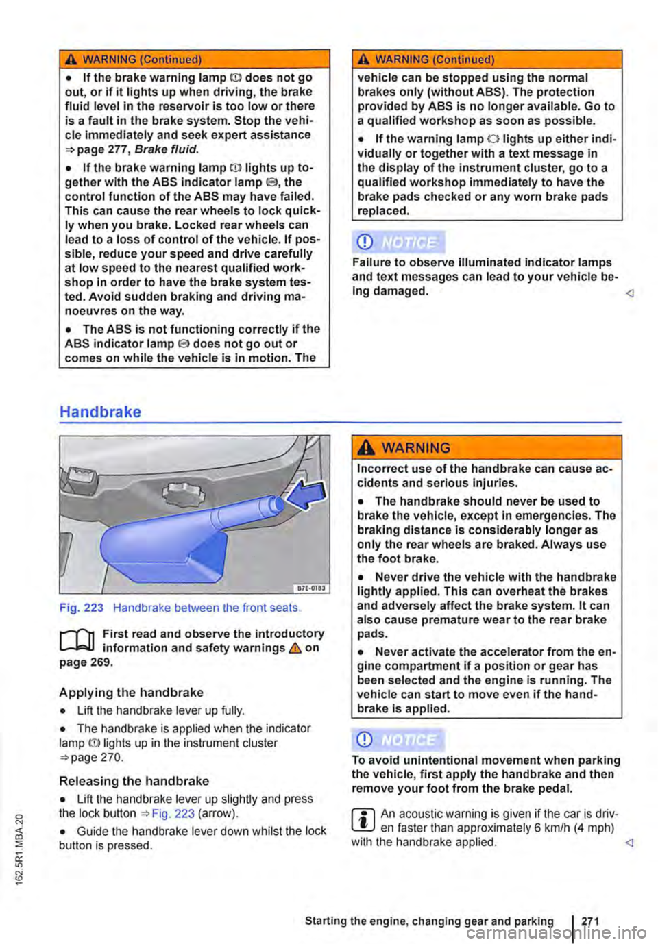
Handbrake
Fig. 223 Handbrake between the front seats.
r--fl1 First read and observe the introductory L-J,::.IJ information and safety warnings & on page 269.
Applying the handbrake
• Lift the handbrake lever up fully.
• The handbrake is applied when the indicator lamp ID lights up in the instrument cluster =-page 270.
Releasing the handbrake
• Lift the handbrake lever up slightly and press the lock button ::.Fig. 223 (arrow).
• Guide the handbrake lever down whilst the lock button is pressed.
A WARNING (Continued)
vehicle can be stopped using the normal brakes only (without ABS). The protection provided by ABS is no longer available. Go to a qualified workshop as soon as possible.
• If the warning lamp 0 lights up either indi-vidually or together with a text message in the display of the instrument cluster, go to a qualified workshop immediately to have the brake pads checked or any worn brake pads replaced.
CD
Failure to observe illuminated indicator lamps and text messages can lead to your vehicle be-Ing damaged.
Incorrect use of the handbrake can cause ac-cidents and serious Injuries.
• The handbrake should never be used to brake the vehicle, except in emergencies. The braking distance is considerably longer as only the rear wheels are braked. Always use the foot brake.
• Never drive the vehicle with the handbrake lightly applied. This can overheat the brakes and adversely affect the brake system. lt can also cause premature wear to the rear brake pads.
• Never activate the accelerator from the en-gine compartment if a position or gear has been selected and the engine is running. The vehicle can start to move even if the hand-brake Is applied.
CD
To avoid unintentional movement when parking the vehicle, first apply the handbrake and then remove your foot from the brake pedal.
r::l An acoustic warning is given if the car is driv-L.!:.J en faster than approximately 6 km/h (4 mph) with the handbrake applied.