VOLKSWAGEN TRANSPORTER 2015 Owner´s Manual
Manufacturer: VOLKSWAGEN, Model Year: 2015, Model line: TRANSPORTER, Model: VOLKSWAGEN TRANSPORTER 2015Pages: 486, PDF Size: 72.17 MB
Page 191 of 486
When the mobile telephone has been paired with the rear-seat telephony system via Bluetooth, the following applies:
• There is a connection between the mobile tele-phone and the microphone at the rear on the right in the passenger compartment headliner.
• Incoming calls are output over the vehicle loud-speaker in the rear right side trim paneL
• The digital voice enhancement (DVE) is switch-ed off during a telephone calL
When a paired mobile telephone is in the charging base (telephone holder), the following applies:
• The mobile telephone is connected to the exter-nal aerial via the charging base.
• If the vehicle key is in the ignition lock. the bat-tery in the mobile telephone will be charged, if nec-essary.
Using the telephone handset
Active telephone calls can also be conducted by means of the telephone handset 152.
• Open the storage compartment in the armrest of the 2-seat arrangement.
• Pick up the handset during an active telephone calL
The microphone and the vehicle loudspeaker in the side trim panel will then be switched off. The telephone call will only be audible via the tele-phone handset ("Private Mode").
If the handset is replaced in its holder, the micro-phone and the vehicle loudspeaker in the side trim panel will be switched on again and the telephone call will not be ended.
• To end the telephone call, press the corre-sponding button on the mobile telephone.
Deleting the list of all devices from the rear-seat telephony system
• Close the existing Bluetooth connection on the mobile telephone.
• Press and hold button 151@ for longer than 10 seconds.
• A signal will sound to confirm that the data has been deleted.
m All other functions must be carried out direct-L!J ly from the mobile telephone.
Page 192 of 486
Equipment, California
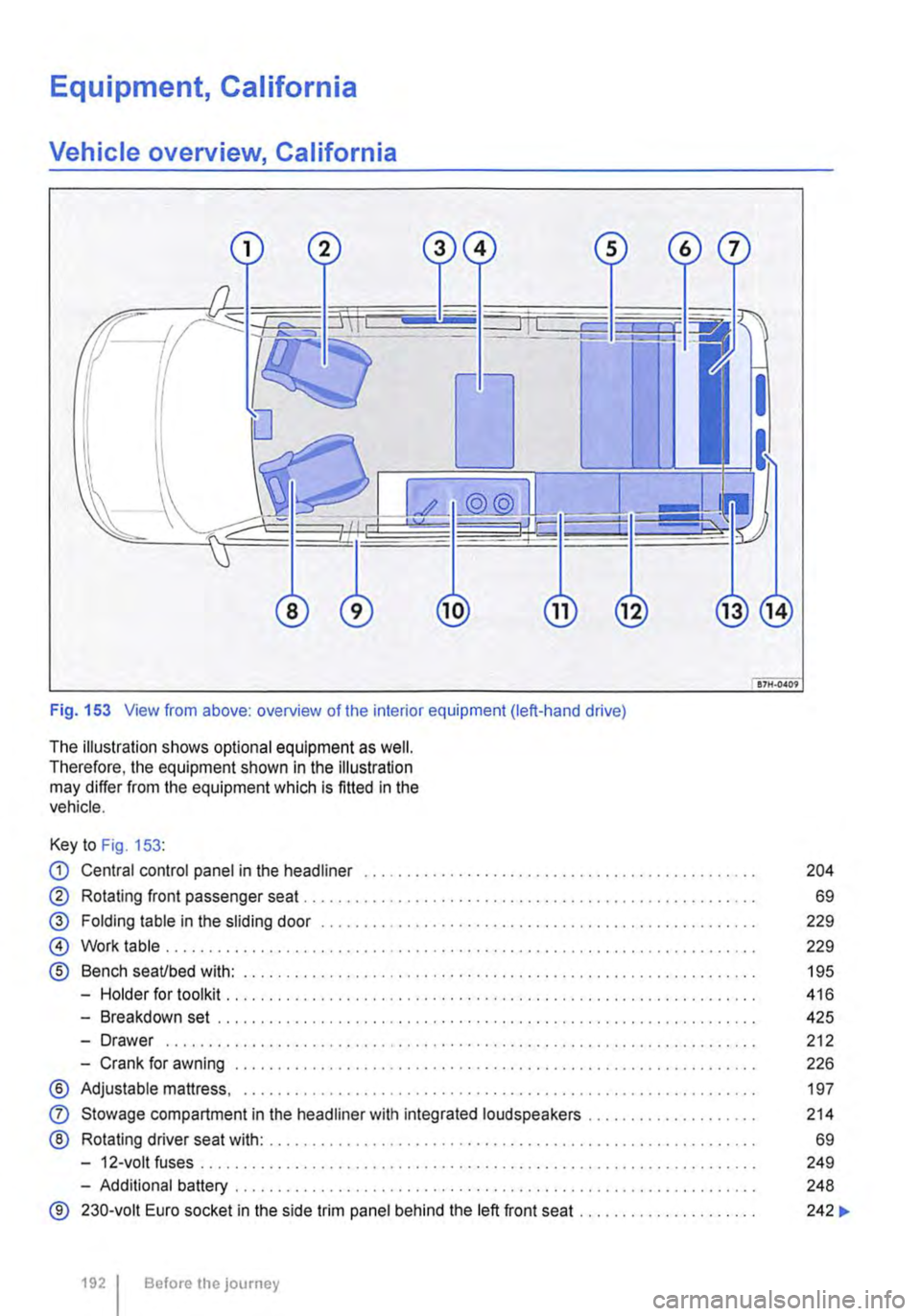
Vehicle overview, California
Fig. 153 View from above: overview of the interior equipment (left-hand drive)
The illustration shows optional equipment as well. Therefore, the equipment shown in the illustration may differ from the equipment which is fitted in the vehicle.
Key to Fig. 153:
CD Central control panel in the headliner . . . . . . . . . . . . . . . . . . . . . . . . . • . . . . . . . . . . . . . . . . . . . . 204
® Rotating front passenger seat . . . . . . . . . . . . . . . . . . . . . . . . . . . . . . . . . . . . . . . . . . . . . . . . . . . 69
@ Folding table in the sliding door . . . . . . . . . . . . . . . . . . . . . . . . . . . . . . . . . . . . . . . . . . . . . . 229
@ Work table . . . . . . . . . . . . . . . . . . . . . . . . . . . . . . . . . . . . . . . . . . . . . . . . . . . . . . . . . . . . . . . . . . 229
® Bench seaUbed with: . . . . . . . . . . . . . . . . . . . . . . . . . . . . . . . . . . . . . . . . . . . . . . . . . . . 195
-Holder for toolkit .......... .
-Breakdown set ..................................................... .
-Drawer ................................................................. · · ·
-Crank for awning .............................................•..............
® Adjustable mattress, ............................................•...............
0
®
Stowage compartment in the headliner with integrated loudspeakers ................... .
Rotating driver seat with: ........................................................ .
-12-volt fuses ..
-Additional battery ........... .
® 230-volt Euro socket in the side trim panel behind the left front seat ..
1921 Before the journey
416
425
212
226
197
214
69
249
248
242 ...
Page 193 of 486
@ Kitchen unit with:
-Gas cooker ................................... . 233
242
242
-230-volt grounded safety socket ................. .
-12-volt socket .............................•..................................
-Cupboard with two sliding doors
-Drawer
-Waste water tank with drain lever and opening for cleaning ...... . 237
-First aid kit on the rear panel of the left stowage compartment in the cupboard
@ Refrigerator box ...
@ Wardrobe with:
241
-Cleaning opening for fresh water tank . . . . . . . . . . . . . . . . . . . . . . . . . . . . . . . . . . . . . . . 237
-Second additional battery . . . . . ........ , . . . . . . . . . . . . . . . . . . . . . . . . . . 248
-Lockable stowage compartment . . . . . . . . . . . . . . . . . . . . . . . . . . . . . . . . . . . . . . . . . . . . . . . . 214
@ Stowage area with:
-Residual current circuit breaker ............... , ...... . 247
233
229
-Gas bottle holder .................. .
® Tailgate with room for stowing two camping chairs
Number of seats
The vehicle has a total of 4 seats: 2 at the front and 2 at the rear. Each seat is equipped with a seat belt.
Retrofitting seats
Additional seats can be retrofitted, provided that the maximum number of seats quoted by the man-ufacturer is not exceeded. For this purpose, seat anchor points should be fitted to the vehicle floor by a specialist workshop in accordance with Volks-wagen AG guidelines.
These additional seats must also have seat belt anchor points and suitable seat belts.
The Volkswagen Commercial Vehicles dealership can provide you with more information on retrofit-ting seats.
Furniture Catches
The flaps and doors are fitted with furniture catch-es to prevent them from opening when the vehicle is in motion.
Seat functions, rear, California
ClJ Introduction
This chapter contains information on the following subjects:
Bench seat/bed . . . . . . . . . . . . . . . . . . . . • • . . . 195
Bed (bench seat/bed) . . . . . . . . . . . 196 Mattress, bench seat/bed . . . . . . . . . . . . . . . . . 197
Components of the mattress, 3-seat bench . . 198
To open the doors in the kitchen unit, press and hold the catch. Slide the door open.
Equipment accessible only from the outside of the vehicle
• Opening for filling the fresh water tank on the rear left side of the vehicle (with lockable lid and separate key)
• 230-volt electrical feed on the rear left side of the vehicle (with flap cover)
• Fresh water tank drain opening under the vehi-cle.
• Waste water tank drain opening under the vehi-cle.
• Awning rails on the left and right side of the top of the vehicle on the roof frame.
• Awning adapter on left (if vehicle is fitted with an awning) and on right in the awning rail.
• Awning: attach to aluminium rail on right side over sliding door only.
Mattress for a medium-length bed, 3-seat bench . . . . . . . . . . . . . . . . . . . . . . . . . . . . 199 Mattress for a long bed, 3-seat bench . . . . . . . 201 Stowing the mattress, 3-seat bench . . . . . . . . 203 .,..
Equipment, California 1193
Page 194 of 486
Additional information and warnings:
• Sitting correctly and safely 61
. • Seat functions, rear 72
• Seat belts 79
• Airbag system 87
• Child seats (accessories) 96
• Luggage compartment 130
• Stowage 150
• Central table 155
,A WARNING
Incorrect use of the seat functions can cause serious Injuries.
• Always assume a correct sitting position before you drive and maintain this position throughout the trip. This also applies to all passengers.
• Keep hands, fingers, feet and other body parts away from the moving parts of the seats.
,A WARNING
Incorrect adjustment or removing and fitting single seats and/or the bench seat can cause accidents and severe injuries.
• All adjustments as well as removing/fitting should be carried out only when the vehicle is stationary; otherwise the single seats and/ or the bench seat could move suddenly when the vehicle is in motion. Furthennore, an in-correct seating position is adopted while ad-justing the seat.
• All single seats and the bench seat must always be fitted in their seat rails and must be securely engaged.
194 I Before the journey
A WARNING (Continued)
• Never use the table or the bed while the vehicle Is In motion. All backrests must be In the upright position and securely engaged In this position while the vehicle Is In motion.
• Never fit single seats behind the bench seat.
• Never fit two 3-seat benches In the vehi-cle.
• While the vehicle is In motion the feet of the fitted single seats and/or the bench seat must not be positioned close to the remova-ble covers of the seat rails.
• Never move single seats and/or the bench seat when the vehicle Is on a steep slope. The single seats and/or the bench seat could move automatically and cause Injuries.
• The area for adjustment of the single seats and/or the bench seat should not be re-stricted by any Items.
• While fitting and removing the single seats and/or the bench seat, make sure that the seat feet are not soiled or damaged.
• The rotating single seats in the passenger compartment can be engaged securely only when facing either the front or rear of the ve-hicle.
• Never use child seats in the groups 0 or 0+ on single seats that face the rear of the vehicle.
A CAUTION
Improper use of the bed can cause Injury.
• Never step in the area between the seat Lc_u_s_h_io_n __ a_n_d_t_h_e_b_a_c_kr_e_s_t. ______________
Page 195 of 486
Bench seat/bed
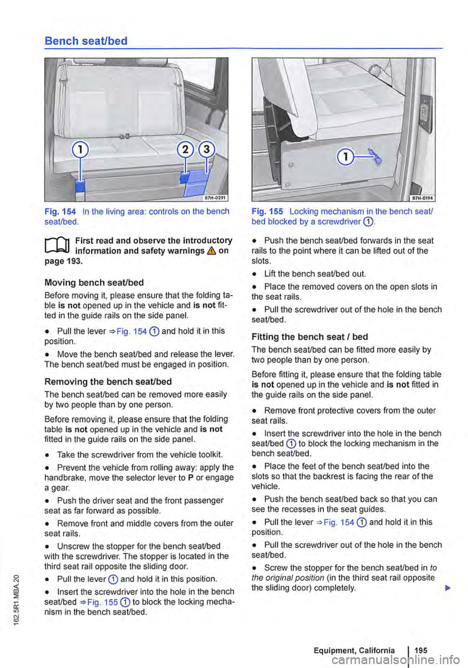
Fig. 154 In the living area: controls on the bench seat/bed.
ill1 First read and observe the introductory l-J::,jJ information and safety warnings & on page 193.
Moving bench seat/bed
Before moving it, please ensure that the folding ta-ble is not opened up in the vehicle and is not fit-ted in the guide rails on the side panel.
• Pull the lever '*Fig. 154 CD and hold it in this position.
• Move the bench seat/bed and release the lever. The bench seat/bed must be engaged in position.
Removing the bench seat/bed
The bench seat/bed can be removed more easily by two people than by one person.
Before removing it, please ensure that the folding table is not opened up in the vehicle and is not fitted in the guide rails on the side panel.
• Take the screwdriver from the vehicle tool kit.
• Prevent the vehicle from rolling away: apply the handbrake, move the selector lever to P or engage a gear.
• Push the driver seat and the front passenger seat as far forward as possible.
• Remove front and middle covers from the outer seat rails.
• Unscrew the stopper for the bench seat/bed with the screwdriver. The stopper is located in the third seat rail opposite the sliding door.
• Pull the lever G) and hold it in this position.
• Insert the screwdriver into the hole in the bench seat/bed =>Fig. 155 G) to block the locking mecha-nism in the bench seat/bed.
Fig. 155 Locking mechanism in lhe bench seat/ bed blocked by a screwdriver G).
• Push the bench seat/bed forwards in the seat rails to the point where it can be lifted out of the slots.
• Lift the bench seat/bed out.
• Place the removed covers on the open slots in the seat rails.
• Pull the screwdriver out of the hole in the bench seat/bed.
Fitting the bench seat I bed
The bench seat/bed can be fitted more easily by two people than by one person.
Before fitting it, please ensure that the folding table is not opened up in the vehicle and is not fitted in the guide rails on the side panel.
• Remove front protective covers from the outer seat rails.
• Insert the screwdriver into the hole in the bench seat/bed G) to block the locking mechanism in the bench seat/bed.
• Place the feet of the bench seat/bed into the slots so that the backrest is facing the rear of the vehicle.
• Push the bench seat/bed back so that you can see the recesses in the seat guides.
• Pull the lever =>Fig. 154 G) and hold it in this position.
• Pull the screwdriver out of the hole in the bench seat/bed.
• Screw the stopper for the bench seat/bed in to the original position (in the third seat rail opposite the sliding door) completely. .,.
Equipment, California 195
Page 196 of 486
• Make sure that the backrest of the bench seaU bed is in the upright position and securely engag-ed.
Bed (bench seat/bed)
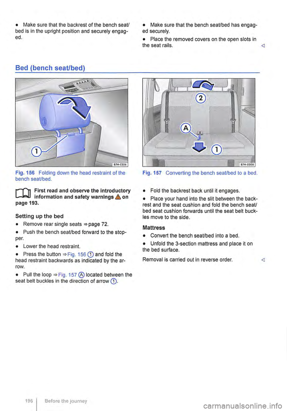
Fig. 156 Folding down the head restraint of the bench seaUbed.
r-111 First read and observe the Introductory 1-J,::JJ information and safety warnings & on page 193.
Setting up the bed
• Remove rear single seats =>page 72.
• Push the bench seaUbed forward to the stop-per.
• Lower the head restraint.
• Press the button =>Fig. 156 G) and fold the head restraint backwards as indicated by the ar-row.
• Pull the loop =>Fig. 157 ® located between the seat belt buckles in the direction of arrow G).
1961 Before the journey
• Make sure that the bench seaUbed has engag-ed securely.
• Place the removed covers on the open slots in the seat rails.
• Fold the backrest back until it engages.
• Place your hand into the slit between the back-rest and the seat cushion and fold the bench seaU bed seat cushion forwards until the seat belt buck-les move to the side.
Mattress
• Convert the bench seaUbed into a bed.
• Unfold the 3-section mattress and place it on the bed surface.
Removal is carried out in reverse order.
Page 197 of 486
Mattress, bench seat/bed
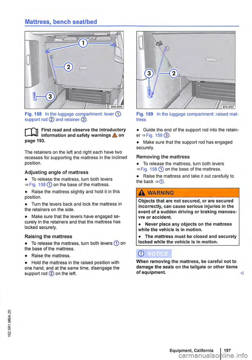
Fig. 158 In the luggage compartment: lever G), support rod @ and retainer@.
r--('n First read and observe the Introductory L.-.J,:.lJ information and safety warnings & on page 193.
The retainers on the left and right each have two recesses for supporting the mattress in the inclined position.
Adjusting angle of mattress
• To release the mattress, turn both levers 158 G) on the base of the mattress.
• Raise the mattress slightly and hold it in this position.
• Turn the levers back and lock the mattress in the retainers on the side.
• Make sure that the levers have engaged se-curely in the retainers and that the mattress has locked securely.
Raising the mattress
• To release the mattress, turn both levers G) on the base of the mattress.
• Raise the mattress.
• Hold the mattress in the raised position with one hand, and at the same time, disengage the support rod@ on the left.
Fig. 159 In the luggage compartment: raised mat-tress
• Guide the end of the support rod into the retain-er 159@.
• Make sure that the support rod has engaged securely.
Removing the mattress
• To release the mattress, turn both levers 158 G) on the base of the mattress.
• Raise the mattress and take it out carefully to the back
A WARNING
Objects that are not secured, or are secured Incorrectly, can cause serious injuries in the event of a sudden driving or braking manoeu-vre or accident.
• Never place any objects on the mattress while the vehicle Is In motion.
• The mattress must be closed and securely locked while the vehicle is In motion.
CD
When removing the mattress, be careful not to damage the seals on the tailgate or other items of equipment.
Page 198 of 486
Components of the mattress, 3-seat bench
87E-0263
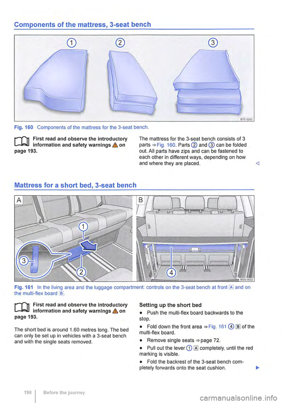
Fig. 160 Components of the mattress for the 3-seat bench .
.--m First read and observe the introductory l.-l=.U information and safety warnings & on page 193.
Mattress for a short bed, 3-seat bench
The mattress for the 3-seat bench consists of 3 parts 160. Parts@ and@ can be folded out. All parts have zips and can be fastened to each other in different ways, depending on how and where they are placed.
.--m First read and observe the Introductory l.-l=.U information and safety warnings & on page 193.
The short bed is around 1.60 metres long. The bed can only be set up in vehicles with a 3-seat bench and with the single seats removed.
198 I Before the journey
Setting up the short bed
• Push the multi-flex board backwards to the stop.
• Fold down the front area 161 @[ID of the multi-flex board.
• Remove single seats 72.
• Pull out the lever CD completely, until the red marking is visible.
• Fold the backrest of the 3-seat bench com-pletely forwards onto the seat cushion. 11>
Page 199 of 486
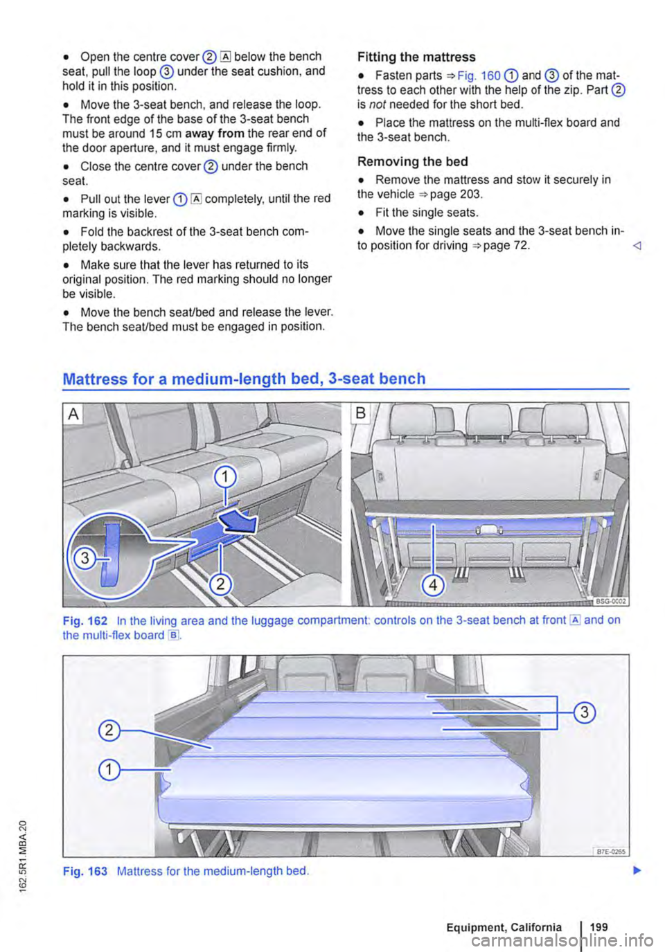
• Open the centre cover® below the bench seat, pull the loop @ under the seat cushion, and hold it in this position.
• Move the 3-seat bench, and release the loop. The front edge of the base of the 3-seat bench must be around 15 cm away from the rear end of the door aperture, and it must engage firmly.
• Close the centre cover® under the bench seat.
• Pull out the lever completely, until the red marlling is visible.
• Fold the backrest of the 3-seat bench com-pletely backwards.
• Make sure that the lever has returned to its original position. The red marking should no longer be visible.
• Move the bench seaVbed and release the lever. The bench seaVbed must be engaged in position.
Fitting the mattress
• Fasten parts =>Fig. 160 G) and @ of the mat-tress to each other with the help of the zip. Part® is not needed for the short bed.
• Place the mattress on the multi-flex board and the 3-seat bench.
Removing the bed
• Remove the mattress and stow it securely in the vehicle =>page 203.
• Fit the single seats.
• Move the single seats and the 3-seat bench in-to position for driving =>page 72.
Fig. 162 In the living area and the luggage compartment. controls on the 3-seat bench at front E and on the multi-flex board e .
Fig. 163 Mattress for the medium-length bed.
Equipment, California 199
Page 200 of 486
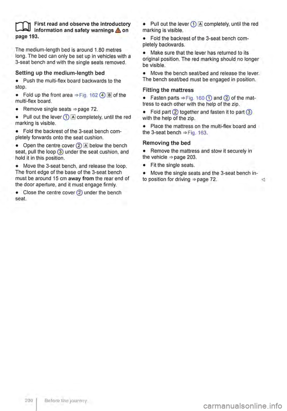
,...-m First read and observe the Introductory L--W.I Information and safety warnings & on page 193.
The medium-length bed is around 1.80 metres long. The bed can only be set up In vehicles with a 3-seat bench and with the single seats removed.
Setting up the medium-length bed
• Push the multi-flex board backwards to the stop.
• Fold up the front area 162 @!ID of the multi-flex board.
• Remove single seats 72.
• Pull out the lever completely, until the red marking is visible.
• Fold the backrest of the 3-seat bench com-pletely forwards onto the seat cushion.
• Open the centre below the bench seat, pull the loop @ under the seat cushion, and hold it in this position.
• Move the 3-seat bench, and release the loop. The front edge of the base of the 3-seat bench must be around 15 cm away from the rear end of the door aperture, and it must engage firmly.
• Close the centre cover® under the bench seat.
200 Before tho JOurney
• Pull out the lever completely, until the red marking is visible.
• Fold the backrest of the 3-seat bench com-pletely backwards.
• Make sure that the lever has returned to its original position. The red marking should no longer be visible.
• Move the bench seaUbed and release the lever. The bench seaUbed must be engaged in position.
Fitting the mattress
• Fasten parts 160 CD and® of the mat-tress to each other with the help of the zip.
• Fold part® together and fasten it to part@ with the help of the zip.
• Place the mattress on the multi-flex board and the 3-seat bench 163.
Removing the bed
• Remove the mattress and stow it securely in the vehicle 203.
• Fit the single seats.
• Move the single seats and the 3-seat bench in-to position for driving 72.