heater VOLKSWAGEN TRANSPORTER 2019 User Guide
[x] Cancel search | Manufacturer: VOLKSWAGEN, Model Year: 2019, Model line: TRANSPORTER, Model: VOLKSWAGEN TRANSPORTER 2019Pages: 486, PDF Size: 69.28 MB
Page 205 of 486
Button, control
Display
®
Additional information =>Fig. 168.
To return to initial screen or cancel a setting without saving it
To completely switch off all functions which were activated using the central control panel, e.g. supplementary heating system, refrigerator box, and wake-up time <1
1 9.5 ° c
Fr f."l11 :28
0
Pj
3
0 117H-01S9
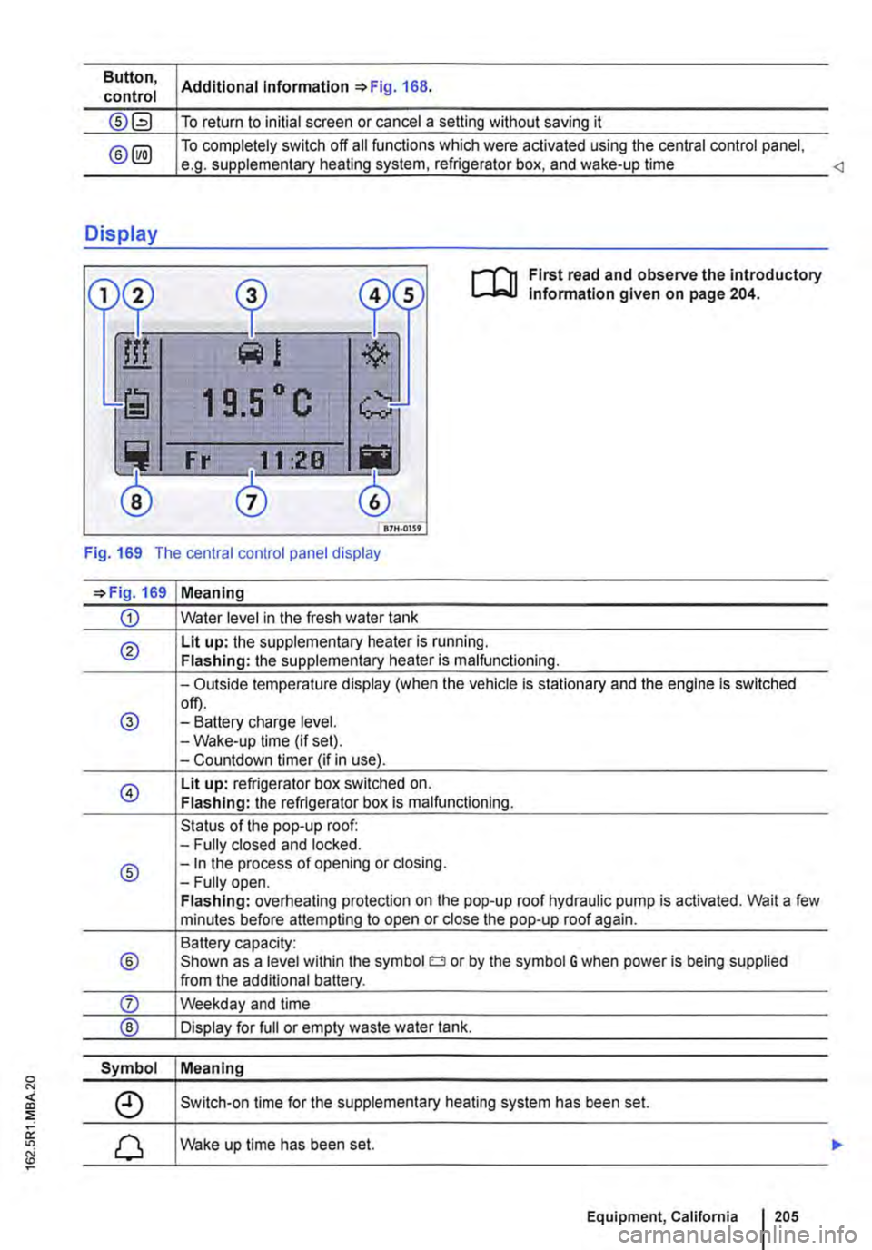
First read and observe the introductory lnfonmation given on page 204.
Fig. 169 The central control panel display
=>Fig. 169 Meaning
CD Water level in the fresh water tank
® Lit up: the supplementary heater is running. Flashing: the supplementary heater is malfunctioning.
-Outside temperature display (when the vehicle is stationary and the engine is switched
@ off). -Battery charge level. -Wake-up time (if set). -Countdown timer (if in use).
@ Lit up: refrigerator box switched on. Flashing: the refrigerator box is malfunctioning.
Status of the pop-up roof: -Fully closed and locked.
® -In the process of opening or closing. -Fully open. Flashing: overheating protection on the pop-up roof hydraulic pump is activated. Wait a few minutes before attempting to open or close the pop-up roof again.
Battery capacity:
® Shown as a level within the symbol o or by the symbol G when power is being supplied from the additional battery.
Symbol Meaning
Switch-on time for the supplementary heating system has been set.
Wake up time has been set.
Equipment, California 1205
Page 243 of 486
• Pump for fresh water
• Auxiliary heater
230-volt grounded safety socket
The 230-volt grounded safety socket is supplied with 230 V alternating current via electrical feed from the external socket 242.
The following electrical consumers are supplied from the 230-volt power supply via the external socket:
• Battery charger
• Depending on the vehicle equipment, the 230-volt grounded safety socket is located in the side trim panel behind the left front seat or on the side of the kitchen unit 246.
230-volt Euro socket
The 230-volt Euro socket is supplied via additional batteries or via an inverter and is located in the side trim panel behind the left front seat 245.
Additional information:
• Electrical sockets page 163
• Battery 362
• Cigarette lighter 161
• Accessories, modifications, repairs and renewal of parts 394
• Fuses 429
• Consumer information 404
• Rectifying faults on the camping equipment 254
High voltage in the electrical system!
• Never pour any liquid over the socket.
• Do not plug any adapters or extension ca-bles into the 230-volt Euro socket. Otherwise the built-in child lock will disengage and pow-er will be supplied to the socket.
• Do not insert any items which will conduct electricity, such as knitting needles, into the contacts of the 230-volt Euro socket.
A WARNING
Improper use of the sockets and electrical ac-cessories can cause fires and severe Injuries.
• Never leave children in the vehicle unat-tended. Sockets and the devices connected to them can be used when the ignition is switched on.
A WARNING (Continued)
• If the electrical device gets too hot, switch off the device Immediately and disconnect it from the socket.
CD
• Observe the operating instructions for any device that you plug into the socket.
• Never exceed the maximum power rating as this could damage the whole vehicle electrical system.
• Only use accessories that have been ap-proved in accordance with valid guidelines concerning electromagnetic compatibility.
• Never feed electricity into the socket.
• Do not plug any heavy devices or connec-tions, such as mains adapters, directly Into the socket.
• Only connect devices to the socket with a voltage that matches the voltage of the socket.
CD
• In order to prevent damage to the electrical system, never connect equipment that gener-ates electricity, such as solar panels or battery chargers for charging the vehicle battery, to the 12-volt socket.
• Only use accessories that have been ap-proved in accordance with current guidelines concerning electromagnetic compatibility.
• In order to avoid damage due to voltage fluctuation, always switch any electrical con-sumers connected to the 12-volt sockets off be-fore switching the ignition or the engine on or off. When the start/stop system automatically switches off and restarts the engine, it is not necessary to switch off any connected electri-cal consumers.
• Never connect electrical devices requiring more electrical power to a 12-volt socket. The vehicle's electrical system can be damaged if the maximum power output is exceeded.
CD
• Observe the operating instructions for any device that you plug Into the socket.
• 230-volt Euro socket:
-Do not plug any heavy devices or connec-tions, such as mains adapters, directly into the socket. .,..
Equipment, California I 243
Page 248 of 486
The batteries will become depleted if electrical consumers such as the auxiliary heater, refrigera-tor box or interior lights are used while the vehicle is stationary for long periods of time without re-charging the batteries. If the battery voltage falls below 11.5 volts, the auxiliary heater cannot be switched on.
The battery compartment and the battery charger are designed specifically for the factory-fitted AGM (absorbed glass mat) batteries &.
Additional batteries
r--f'n First read and observe the introductory information and safety warnings & on page 242.
The factory-fitted AGM batteries are located under the left front seat and in the wardrobe. They have deep discharge protection.
Should the additional batteries be subjected to deep discharge over a long period of time, they could be destroyed.
You can prevent deep discharge by:
• switching off the central control panel after charging,
• removing the fuses for the fresh water pump and the pop-up roof as necessary 249.
AGM batteries are maintenance free. do not leak their electrolyte, are robust and have extremely low gas emissions.
When should the additional battery be charged?
• If the additional battery is not charged by the al-ternator while the engine is running, the additional battery must be charged on the battery charger at regular intervals -every 4 weeks at the latest-for at least 12 hours.
• The additional battery must be recharged for at least 12 hours before the start of a journey if the battery has not been used for an extended period (e.g. seasonal use).
248 I Before the JOurney
A WARNING
If a conventional battery Is charged it will give off a highly explosive mixture of gases.
• Use only AGM batteries of the same type (batteries with the electrolyte absorbed Into a special fibreglass matting) and with the same specifications as the factory-fitted batteries.
• Never use conventional batteries (wet cells with liquid electrolyte).
If a conventional battery Is charged it will give off a highly explosive mixture of gases.
• Use only AGM batteries of the same type (batteries with the electrolyte absorbed into a special fibreglass matting) and with the same specifications as the factory-fitted batteries.
• Never use conventional batteries (wet cells with liquid electrolyte).
Page 251 of 486
Supplementary heater, California
o:JJ Introduction
This chapter contains information on the following subjects:
Programming the supplementary heater. . . . . 251
The supplementary heating system is supplied with fuel from the vehicle fuel tank and can be used when the vehicle is in motion or stationary.
Additional information:
• Central control panel 204
• Supplementary heaters 322
• Rectifying faults on the camping equipment 254
A WARNING
The fumes from the supplementary heating system contain carbon monoxide, which is an odourless and colourless poisonous gas. Carbon monoxide can cause people to lose consciousness. lt can also cause death.
A WARNING (Continued)
• Never start or run the supplementary heat-ing system in unventilated or closed rooms.
• Never programme the auxiliary heater so that it is switched on and run in unventilated or enclosed spaces.
A WARNING
Parts of the exhaust system of the supple-mentary heating system become very hot. This can cause fires.
• Park the vehicle so that no part of the ex-haust system can come into contact with any inflammable material underneath the vehicle, e.g. dry grass.
CD
Do not place any food, medicine or any other heat-sensitive items In front of the vents. Heat-sensitive food, medicine and other items could be either damaged or rendered useless.
,.....-('n First read and observe the introductory L-bl.l information and safety warnings & on page 251.
The built-in timer allows you to program up to sev-en switch-on times.
Functions Submenu Description
New Set daily or day of Turn the rotary/push knob 168@ to change the setting. week. Press the rotary/push knob to confirm the setting and move to the next submenu.
Set the time Set the switch-on time.
Specify the run period. Set the run period for the supplementary heating system. A low battery charge could cause the run period to be cut short.
Select temperature. Select the heating temperature.
Change Change switch-on time. Select the switch-on setting to be changed and select Change. Change the switch-on time as described under New.
Delete Delete switch-on time. Select the switch-on time to be deleted and select Delete. Con-firm entry.
Equipment, California I 251
Page 259 of 486
0 "' <(
"' ::;
oc "' N
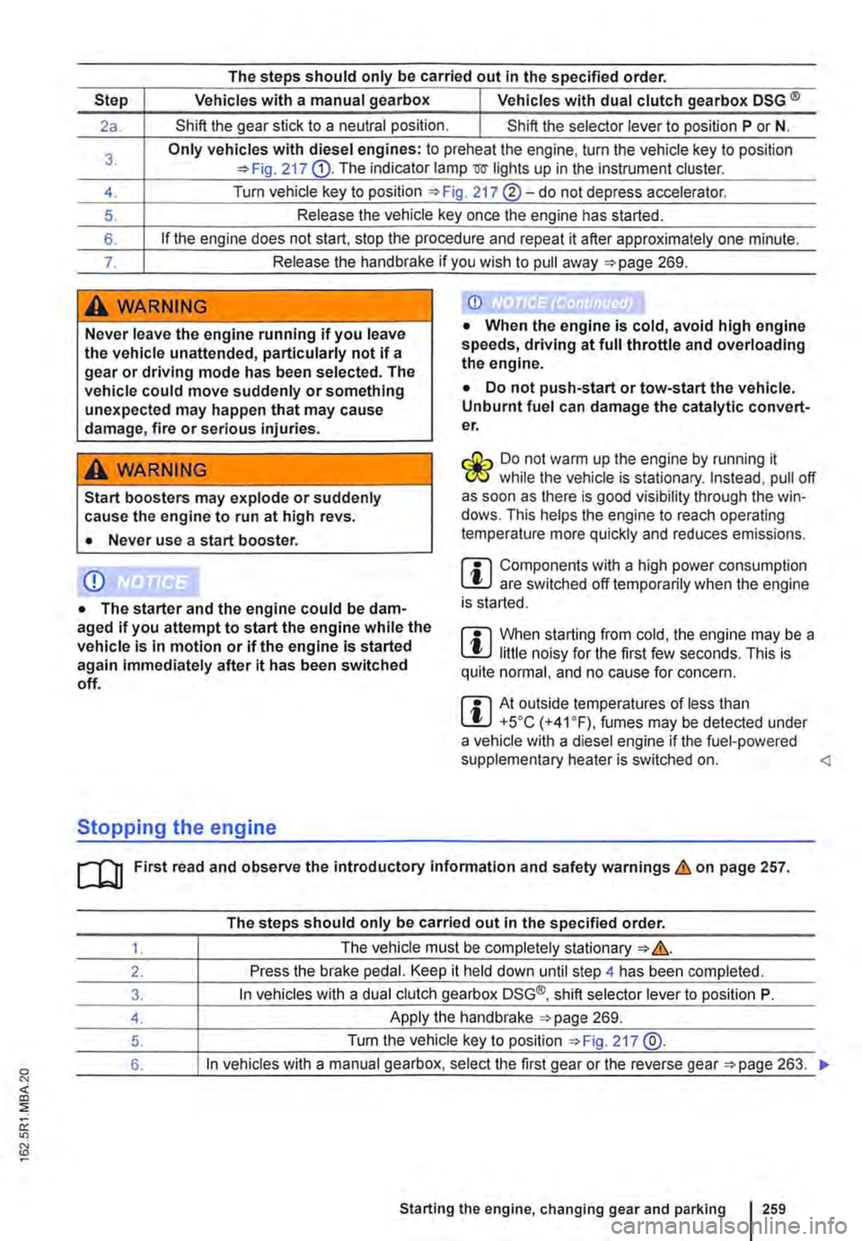
The steps should only be carried out In the specified order.
Step Vehicles with a manual gearbox I Vehicles with dual clutch gearbox DSG ®
2a. Shift the gear stick to a neutral position. I Shift the selector lever to position P or N.
3. Only vehicles with diesel engines: to preheat the engine, turn the vehicle key to position 217 G). The indicator lamp mr lights up in the instrument cluster.
4. Turn vehicle key to position 217 ®-do not depress accelerator.
5. Release the vehicle key once the engine has started.
6. If the engine does not start, stop the procedure and repeat it after approximately one minute.
7. Release the handbrake if you wish to pull away =>page 269.
A WARNING
Never leave the engine running if you leave the vehicle unattended, particularly not if a gear or driving mode has been selected. The vehicle could move suddenly or something unexpected may happen that may cause damage, fire or serious injuries.
A WARNING
Start boosters may explode or suddenly cause the engine to run at high revs.
• Never use a start booster.
CD
• The starter and the engine could be dam-aged if you attempt to start the engine while the vehicle Is In motion or if the engine is started again immediately after it has been switched off.
Stopping the engine
CD
• When the engine is cold, avoid high engine speeds, driving at full throttle and overloading the engine.
• Do not push-start or tow-start the vehicle. Unburnt fuel can damage the catalytic convert-er.
&-, Do not warm up the engine by running it W while the vehicle is stationary. Instead, pull off as soon as there is good visibility through the win· dows. This helps the engine to reach operating temperature more quickly and reduces emissions.
m Components with a high power consumption L!:J are switched off temporarily when the engine is started.
m When starting from cold, the engine may be a L!:J little noisy for the first few seconds. This is quite normal, and no cause for concern.
m At outside temperatures of less than L!:J +5oC (+41°F), fumes may be detected under a vehicle with a diesel engine if the fuel-powered supplementary heater is switched on.
The steps should only be carried out In the specified order.
1. The vehicle must be completely stationary => &.
2. Press the brake pedal. Keep it held down until step 4 has been completed.
3. In vehicles with a dual clutch gearbox DSG®, shift selector lever to position P.
4. Apply the handbrake =>page 269.
5. Turn the vehicle key to position =>Fig. 217 @.
6. In vehicles with a manual gearbox, select the first gear or the reverse gear =>page 263. .,.
Starting the engine, changing gear and parking I 259
Page 322 of 486
Air conditioning system
Heating, ventilating, cooling
o:n Introduction
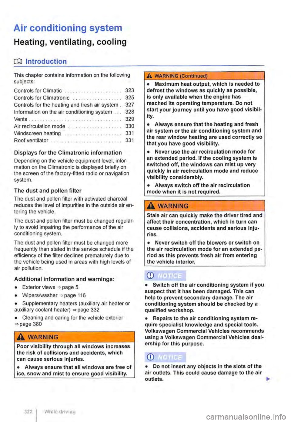
This chapter contains information on the following subjects:
Controls for Climatic . . . . . . . . . . . . . . . . . . . . 323
Controls for Climatronic . . . . . . . . . . . . . . . . . 325
Controls for the heating and fresh air system . 327
Information on the air conditioning system . . . 328
..................... m
Air recirculation mode . . . . . . . • . . . . . . . . . . . . 330
Windscreen heating . . . . . . . . . . . . . . . . . . . . . 331
Roof ventilator . . . . . . . . . . . . . . . . . . . . . . . . . . 331
Displays for the Climatronic information
Depending on the vehicle equipment level, infor-mation on the Climatronic is displayed briefly on the screen of the factory-fitted radio or navigation system.
The dust and pollen filter
The dust and pollen filter with activated charcoal reduces the level of impurities in the outside air en-tering the vehicle.
The dust and pollen filler must be changed regular-ly to avoid impairing the performance of the air conditioning system.
The dust and pollen filter must be changed more frequently than stated in the service schedule if the efficiency of the filter declines prematurely due to the vehicle being used in areas with high levels of air pollution.
Additional information and warnings:
• Exterior views 5
• Wipers/washer 116
• Supplementary heaters (auxiliary air heater or auxiliary coolant heater) 332
• Cleaning and caring for the vehicle exterior 380
A WARNING
Poor visibility through all windows increases the risk of collisions and accidents, which can cause serious injuries.
• Always ensure that all windows are free of ice, snow and mist to ensure good visibility.
3221 While driving
A WARNING (Continued)
• Maximum heat output, which Is needed to defrost the windows as quickly as possible, is only available when the engine has reached Its operating temperature. Do not start your journey until you have good visibil-Ity.
• Always ensure that the heating and fresh air system or the air conditioning system and the rear window heating are used correctly so that you have good visibility.
• Never use the air reclrculatlon mode for an extended period. If the cooling system Is switched off, the windows can mist up very quickly In air reclrculatlon mode and reduce visibility considerably.
• Always switch off the air reclrculatlon mode when it Is not required.
A WARNING
Stale air can quickly make the driver tired and affect their concentration, which In turn can cause collisions, accidents and serious Inju-ries.
• Never switch off the blowers or switch on the air recirculatlon mode for an extended pe· riod as this prevents fresh air from entering the vehicle interior.
• Repairs to the air conditioning system re-quire specialist knowledge and special tools. Volkswagen Commercial Vehicles recommends using a Volkswagen Commercial Vehicles deal-ership for this purpose.
Page 332 of 486
![VOLKSWAGEN TRANSPORTER 2019 User Guide Supplementary heaters (auxiliary air heater or auxiliary
coolant heater)
[Q] Introduction
This chapter contains information on the following subjects:
Controls . . . . . . . . . . . . . . . . . . VOLKSWAGEN TRANSPORTER 2019 User Guide Supplementary heaters (auxiliary air heater or auxiliary
coolant heater)
[Q] Introduction
This chapter contains information on the following subjects:
Controls . . . . . . . . . . . . . . . . . .](/img/18/55779/w960_55779-331.png)
Supplementary heaters (auxiliary air heater or auxiliary
coolant heater)
[Q] Introduction
This chapter contains information on the following subjects:
Controls . . . . . . . . . . . . . . . . . . . . . . . . . . . . . . . 333
Switching the supplementary heating system on and off . . . . . . . . . . . . . . . . . . . . . . . . 334
Remote control . . . . . . . . . . . . . . . . . 335
Programming the supplementary heating system . . . . . . . . . . . . . . . . . . . . . . 338 Switching the child proof lock on and off . . . . . 339
Operation . . . . . . . . . . . . . . . . . . . . . . . . 339
The supplementary heating system is supplied with fuel from the vehicle fuel tank and can be used when the vehicle is in motion or stationary. Electri-cal power is supplied by the vehicle battery.
The auxiliary air heater runs in air recirculation mode and heats the vehicle interior. it has sepa-rate vents in the passenger compartment =>Fig. 265.
The auxiliary coolant heater heats the heating circuit. Heat is guided into the vehicle interior via the vents for the heating or air conditioning system. With the auxiliary coolant heater, it is possible to switch between heating and ventilating.
Additional information and warnings:
• Supplementary heater in the California =>page 192
• Filling the tank =>page 340
• Battery =>page 362
Swallowing batteries with a diameter of 20 mm or other lithium batteries can result in severe or even fatal injuries within a very short period of time.
• Always keep the vehicle key, key ring with batteries, spare batteries, round cells and other batteries that are larger than 20 mm out of the reach of children.
332 I While driving
• Call for medical help immediately you pect that someone has swallowed a batte
A WARNING
The fumes from the supplementary heating system contain carbon monoxide, which is an odourless and colourless poisonous gas. Carbon monoxide can cause people to lose consciousness. lt can also cause death.
• Never start or run the supplementary heat-ing system In unventllated or closed rooms.
• Never program the supplementary heating system so that Is switched on and run In un-ventilated or enclosed areas.
A WARNING
Parts of the exhaust system of the supple-mentary heating system become very hot. This can cause fires.
• Park the vehicle so that no part of the ex-haust system can come Into contact with any Inflammable material underneath the vehicle, e.g. dry grass.
Q)
Do not place any food, medicine or any other temperature-sensitive items in front of the vents. Heat-sensitive food, medicine and other items could be either damaged or rendered useless.
m After starting the engine with a discharged W vehicle battery, or after the battery has been changed, system settings (time, date, personal convenience settings and programming) may have been changed or deleted. Check and correct the settings as necessary once the vehicle battery has been sufficiently charged.
Page 333 of 486
Controls
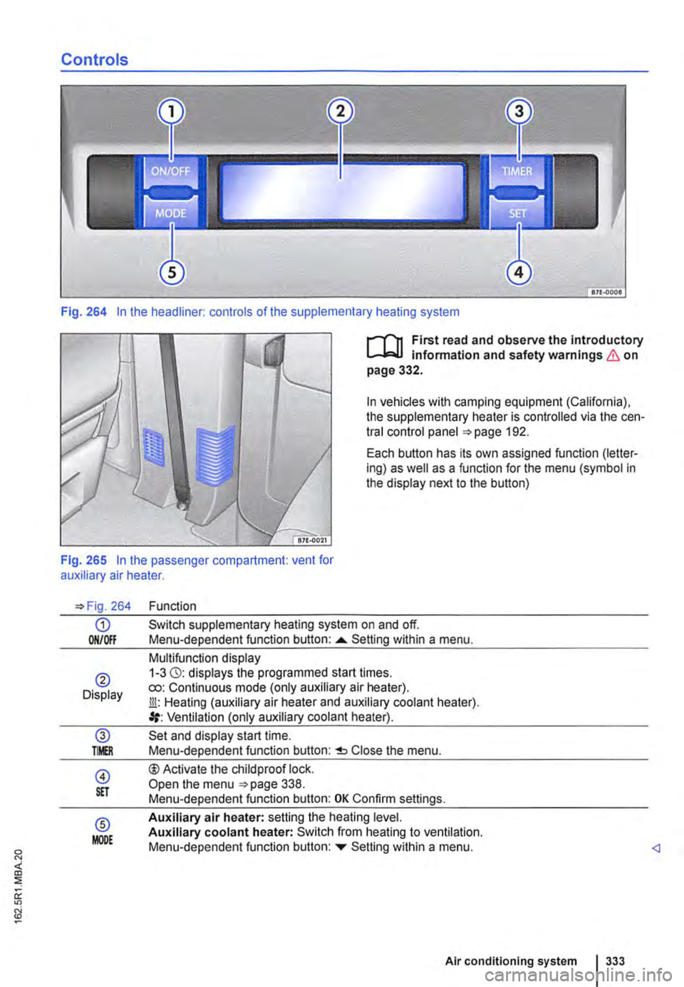
Fig. 264 In the headliner: controls of the supplementary heating system
I""""T'n First read and observe the introductory l.-..1=.1.1 infonmatlon and safety warnings & on page 332.
In vehicles with camping equipment (California), the supplementary heater is controlled via the cen-tral control panel 192.
Each button has its own assigned function (letter-ing) as well as a function for the menu (symbol in the display next to the button)
Fig. 265 In the passenger compartment: vent for auxiliary air heater.
264
G) ON/Off
® Display
@ TMR
@ S£T
® MODE
Function
Switch supplementary heating system on and off. Menu-dependent function button: ......_ Setting within a menu.
Multifunction display 1-3 (3): displays the programmed start times. ro: Continuous mode (only auxiliary air heater). Jli: Heating (auxiliary air heater and auxiliary coolant heater). Ventilation (only auxiliary coolant heater).
Set and display start time. Menu-dependent function button: Close the menu.
®Activate the child proof lock. Open the menu 338. Menu-dependent function button: OK Confirm settings.
Auxiliary air heater: setting the heating level. Auxiliary coolant heater: Switch from heating to ventilation. Menu-dependent function button: ...,. Setting within a menu.
Air conditioning system I 333
Page 334 of 486
Switching the supplementary heating system on and off
r-Y'n First read and observe the introductory L-J.:.I.I information and safety warnings & on page 332.
In vehicles with camping equipment (California), the supplementary heater is controlled via the cen-tral control panel =>page 192.
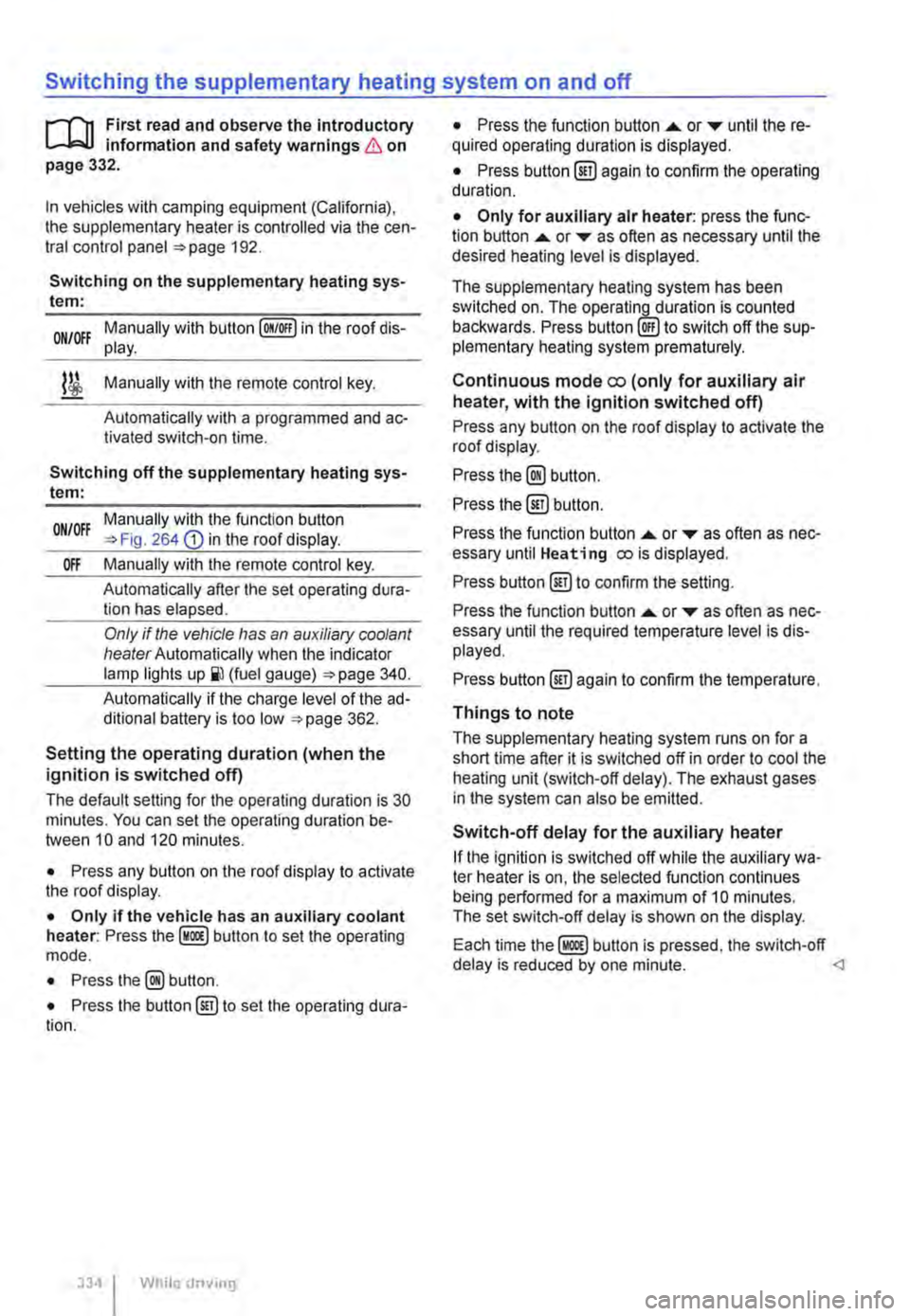
Switching on the supplementary heating sys-tem:
Manually with button [011/0IF) in the roof dis-ON/OFF play.
l/i Manually with the remote control key.
Automatically with a programmed and ac-tivated switch-on time.
Switching off the supplementary heating sys-tem:
ON/OFF Manually with the function button =>Fig. 264 CD in the roof display.
Off Manually with the remote control key.
Automatically after the set operating dura-tion has elapsed.
Only if the vehicle has an auxiliary coolant heater Automatically when the indicator lamp lights (fuel gauge) =>page 340.
Automatically if the charge level of the ad-ditional battery is too low =>page 362.
Setting the operating duration (when the ignition is switched off)
The default setting for the operating duration is 30 minutes. You can set the operating duration be-tween 10 and 120 minutes.
• Press any button on the roof display to activate the roof display.
• Only if the vehicle has an auxiliary coolant heater: Press the button to set the operating mode.
• Press the@ button.
• Press the button@) to set the operating dura-tion.
334 I While driv1ng
• Press the function button ....,. or T until the re-quired operating duration is displayed.
• Press button@) again to confirm the operating duration.
• Only for auxiliary air heater: press the func-tion button ....,. or ... as often as necessary until the desired heating level is displayed.
The supplementary heating system has been switched on. The operatin_lLduration is counted backwards. Press to switch off the sup-plementary heating system prematurely.
Continuous mode eo (only for auxiliary air heater, with the ignition switched off)
Press any button on the roof display to activate the roof display.
Press the@) button.
Press the @) button.
Press the function button ....,. or ... as often as nec-essary until Heating eo is displayed.
Press button @)to confirm the setting.
Press the function button ....,. or T as often as nec-essary until the required temperature level is dis-played.
Press button @)again to confirm the temperature.
Things to note
The supplementary heating system runs on for a short time after it is switched off in order to cool the heating unit (switch-off delay). The exhaust gases in the system can also be emitted.
Switch-off delay for the auxiliary heater
If the ignition is switched off while the auxiliary wa-ter heater is on, the selected function continues being performed for a maximum of 10 minutes. The set switch-off delay is shown on the display.
Each time button is pressed, the switch-off delay is reduced by one minute.
Page 335 of 486
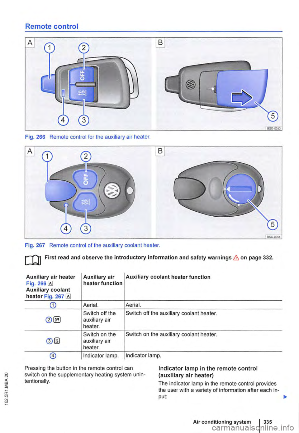
Remote control
B
BSG·OOS3
Fig. 266 Remote control for the auxiliary air heater.
A
BSG-0054
Fig. 267 Remote control of the auxiliary coolant heater.
ru First read and observe the introductory Information and safety warnings & on page 332.
Auxiliary air heater Auxiliary air Auxiliary coolant heater function Fig. heater function Auxiliary coolant heater Fig. 267
CD Aerial. Aerial.
Switch off the Switch off the auxiliary coolant heater.
0@) auxiliary air heater.
Switch on the Switch on the auxiliary coolant heater.
0@ auxiliary air heater.
@) Indicator lamp. Indicator lamp.
Pressing the button in the remote control can switch on the supplementary heating system unin-tentionally.
Indicator lamp in the remote control (auxiliary air heater)
The indicator lamp in the remote control provides the user with a variety of information after each in-put: 1>-
Air conditioning system 335