turn signal VOLKSWAGEN TRANSPORTER 2021 Owner's Manual
[x] Cancel search | Manufacturer: VOLKSWAGEN, Model Year: 2021, Model line: TRANSPORTER, Model: VOLKSWAGEN TRANSPORTER 2021Pages: 486, PDF Size: 69.28 MB
Page 305 of 486
A WARNING
Failure to switch off the adaptive cruise con-trol (ACC) in the above-mentioned situations can cause accidents and result in serious in-juries.
Special driving situations
A WARNING (Continued)
• Always switch off the adaptive cruise con-trol (ACC) in critical driving situations.
m Failure to switch off the adaptive cruise con-L!:..J trot (ACC) in the above-mentioned situations can cause a violation of legal requirements.
( B>G.0028
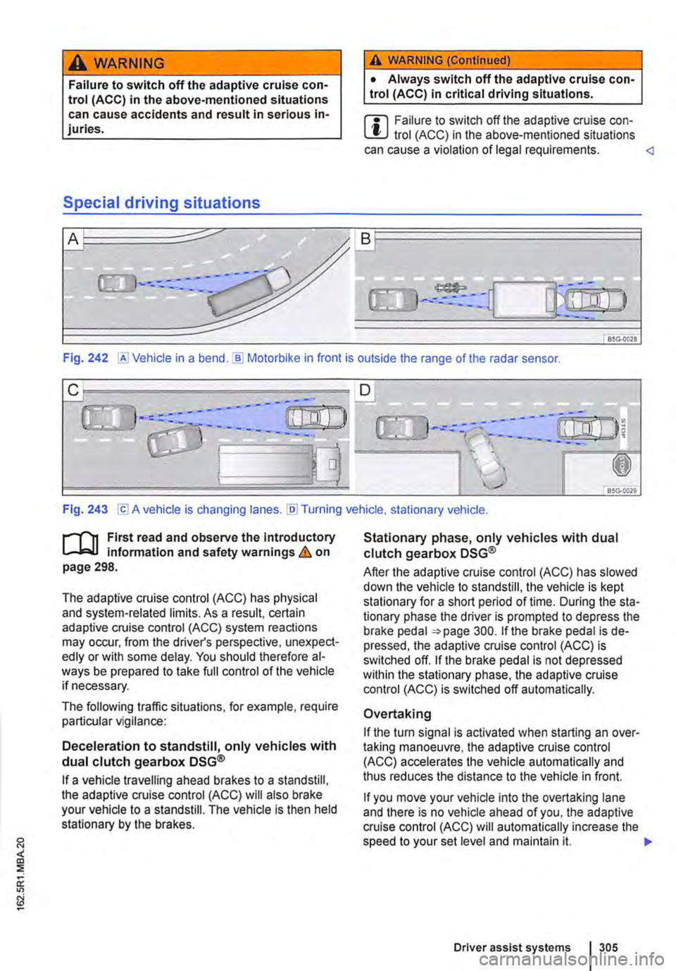
Fig. 242 @Vehicle in a bend.]) Motorbike in front is outside the range of the radar sensor.
Fig. 243 [Cl A vehicle is changing lanes. [li] Turning vehicle, stationary vehicle.
n"'n First read and observe the introductory L-J,:,.lJ information and safety warnings & on page 298.
The adaptive cruise control (ACC) has physical and system-related limits. As a result, certain adaptive cruise control (ACC) system reactions may occur, from the driver's perspective, unexpect-edly or with some delay. You should therefore al-ways be prepared to take full control of the vehicle if necessary.
The following traffic situations, for example, require particular vigilance:
Deceleration to standstill, only vehicles with dual clutch gearbox DSG®
If a vehicle travelling ahead brakes to a standstill, the adaptive cruise control (ACC) will also brake your vehicle to a standstill. The vehicle is then held stationary by the brakes.
Stationary phase, only vehicles with dual clutch gearbox DSG®
After the adaptive cruise control (ACC) has slowed down the vehicle to standstill, the vehicle is kept stationary for a short period of time. During the sta-tionary phase the driver is prompted to depress the brake pedal 300. If the brake pedal is de-pressed, the adaptive cruise control (ACC) is switched off. If the brake pedal is not depressed within the stationary phase, the adaptive cruise control (ACC) is switched off automatically.
Overtaking
If the tu m signal is activated when starting an over-taking manoeuvre, the adaptive cruise control (ACC) accelerates the vehicle automatically and thus reduces the distance to the vehicle in front.
If you move your vehicle into the overtaking lane and there is no vehicle ahead of you, the adaptive cruise control (ACC) will automatically increase the speed to your set level and maintain it. .,..
Driver assist systems I 305
Page 306 of 486
Acceleration can be stopped at any time by de-pressing the brake pedal or pressing the(@ or @ button on the multifunction steering wheel 302.
When driving through bends
While driving through bends, the radar sensor may sometimes lose the vehicle travelling ahead or may react to a vehicle in the next lane 242 !Al. In such situations, the vehicle might decelerate unnecessarily or not react to the vehicle in front. In this case the driver must override the adaptive cruise control (ACC) by depressing the accelerator, or interrupt the braking procedure by depressing the brake pedal or pressing or @ button on the multifunction steering wheel 302.
Driving in tunnels
The radar sensor function may be restricted in tun-nels. Switch off the adaptive cruise control (ACC) in tunnels.
Narrow vehicles and a zig-zag traffic situation
Narrow vehicles and vehicles travelling slightly to the left or right of your vehicle will only be recog-nised by the radar sensor once they have entered the radar range 242@ This applies in par-ticular to narrow vehicles such as motorbikes. If re-quired, brake the vehicle yourself.
Vehicles with special load or special equipment
Any load or accessories on other vehicles that pro-trude from the side, rear or over the roof of the ve-hicle may not be detected by the adaptive cruise control (ACC) .
Switch off the adaptive cruise control (ACC) when the vehicle ahead has special load or special equipment, or while overtaking vehicles of this kind. If required. brake the vehicle yourself.
When other vehicles change lanes
Vehicles that are very close when they move into your lane can only be detected by the radar sen-sors when they have moved into the sensor range. This means that the adaptive cruise control (ACC) may have a delayed reaction =>Fig. 243@]. If re-quired, brake the vehicle yourself.
Stationary vehicles
The adaptive cruise control (ACC) does not detect stationary objects during a journey, e.g. stationary traffic or a vehicle that has broken down.
306 I While driving
If a stationary vehicle is hidden behind a vehicle that has been detected by the adaptive cruise con-trol (ACC) and this vehicle turns off the road or changes lane, the adaptive cruise control (ACC) will not be able to react to the stationary vehicle 243 [Q]. If required, brake the vehicle your-self.
Oncoming vehicles and vehicles crossing your path
The adaptive cruise control (ACC) does not react to approaching vehicles or vehicles crossing your path.
Metal objects
Metal objects, such as tracks in the road or metal plates used in roadworks, can confuse the radar sensor and cause incorrect reactions from the adaptive cruise control (ACC) .
Possible radar sensor function impairments
The adaptive cruise control (ACC) will switch off temporarily if the radar sensor function is impaired, e.g. due to heavy rain, spray, snow, ice or mud. A corresponding message will appear on the instru-ment cluster display. Clean the radar sensors as required.
The adaptive cruise control (ACC) will automatical-ly be available again as soon as the radar sensors are no longer impaired. The message on the in-strument cluster display goes out, and the adaptive cruise control (ACC) can be reactivated.
Strong reflected radiation of the radar signal, e.g. in multi-storey car parks, can impair the function of the radar sensor.
Towing a trailer
The adaptive cruise control (ACC) operates with reduced dynamics when the vehicle is towing a trailer.
Overheated brakes
If the brakes overheat, e.g. following heavy braking or when driving down steep inclines for long peri-ods, the adaptive cruise control (ACC) may be de-activated temporarily. A corresponding message will appear on the instrument cluster display. lt is then not possible to activate the adaptive cruise control (ACC).
As soon as the temperature of the brakes has de-creased sufficiently, the adaptive cruise control (ACC) can be activated again. The message on the instrument cluster display goes out. If the mes-sage ACC not ava i 1 able does not go out for a long time, there is a fault. Go to a qualified work-shop. Volkswagen recommends using a Volkswa-gen dealership for this purpose.
Page 314 of 486
Operation
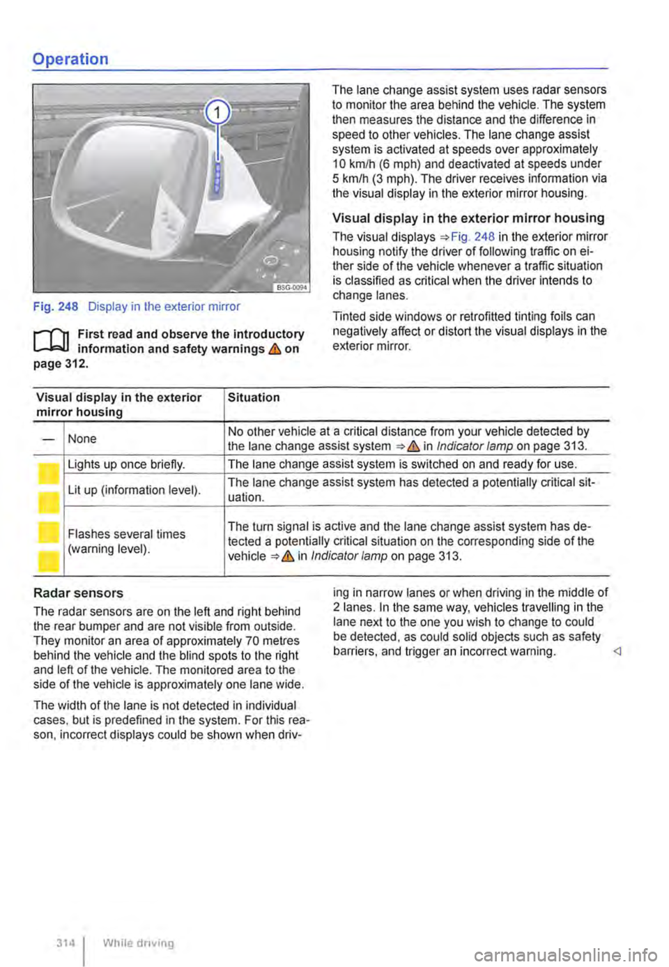
Fig. 248 Display in the exterior mirror
r-f"n First read and observe the introductory L-W! information and safety warnings & on page 312.
Visual display in the exterior Situation mirror housing
The lane change assist system uses radar sensors to monitor the area behind the vehicle. The system then measures the distance and the difference in speed to other vehicles. The lane change assist system is activated at speeds over approximately 10 km/h (6 m ph) and deactivated at speeds under 5 km/h (3 mph). The driver receives infonmation via the visual display in the exterior mirror housing.
Visual display in the exterior mirror housing
The visual displays 248 in the exterior mirror housing notify the driver of following traffic on ei-ther side of the vehicle whenever a traffic situation is classified as critical when the driver intends to change lanes.
Tinted side windows or retrofitted tinting foils can negatively affect or distort the visual displays in the exterior mirror.
None No other vehicle at a critical distance from your vehicle detected by -the lane change assist system & in Indicator lamp on page 313.
Lights up once briefly. The lane change assist system is switched on and ready for use.
Lit up (information level). The lane change assist system has detected a potentially critical sit-uation.
Flashes several times The turn signal is active and the lane change assist system has de-
(warning level). tected a potentially critical situation on the corresponding side of the in Indicator/amp on page 313.
Radar sensors
The radar sensors are on the left and right behind the rear bumper and are not visible from outside. They monitor an area of approximately 70 metres behind the vehicle and the blind spots to the right and left of the vehicle. The monitored area to the side of the vehicle is approximately one lane wide.
The width of the lane is not detected in individual cases. but is predefined in the system. For this rea-son. incorrect displays could be shown when driv-
314 I While driving
ing in narrow lanes or when driving in the middle of 2 lanes. In the same way, vehicles travelling in the lane next to the one you wish to change to could be detected, as could solid objects such as safety barriers. and trigger an incorrect warning.
Page 336 of 486
Action I Indicator lamp Fig. 266
Switch on the auxiliary air heater by pressing button @ (for approx. 2 sec-onds).
Switch off the auxiliary air heater by pressing button ® (for approx. 2 sec-onds).
Lights up, when the button is pressed, and then flashes in green in short intervals for approximately 30 seconds.
Lights up, when the button is pressed, and then flashes in red in short intervals for approximately 30 seconds.
Lights up in green, when the button is pressed, and then flashes Remote control is out of range Attempt in red in short intervals for approximately 10 seconds. The auxili-to switch on by pressing the button @. ary air heater is not switched on.
System fault. Attempt to switch on by pressing the button @.
Lights up in green, when the button is pressed, and then flashes in red in very short intervals for approximately 10 seconds. The auxiliary air heater is not switched on.
The battery in the remote control is dis-charged. Not flashing, lamps not lit up. The auxiliary air heater cannot be controlled using the radio remote control.
Indicator lamp in the remote control (auxiliary coolant heater)
The indicator lamp in the remote control provides the user with a variety of information after each in-put:
Action Indicator lamp Fig. 267
Switch on the auxiliary coolant heater by Lights up in green for approximately 2 seconds after the but-pressing button@ (for approx. 1 second). ton has been pressed.
Switch off the auxiliary coolant heater by Lights up in red for approximately 2 seconds after the button pressing button® (for approx. 1 second). has been pressed.
Attempt to switch on or off using button @ Flashes green or red in short intervals for approximately or@. No signal was received a). 2 seconds.
Attempt to switch on: flashes green in very short intervals for Attempt to switch on or off using button@ approximately 2 seconds. The switch-on signal is not pro-or@. The auxiliary coolant heater is cessed. blocked b). Attempt to switch off: lights up red for approximately 2 sec-onds. The switch-off signal is not processed.
Attempt to switch on: lights up orange for approximately
Attempt to switch on or off using button@ 2 seconds, then turns green for another 2 seconds. The
or® when the battery in the remote con-auxiliary coolant heater is switched on. Attempt to switch off: lights up orange for approximately trot is low. 2 seconds, then turns red for another 2 seconds. The auxili-ary coolant heater is switched off.
Attempt to switch on: lights up orange for approximately
Attempt to switch on or off using button @ 2 seconds, then flashes green in short intervals for another
or® when the battery in the remote con-2 seconds. The switch-on signal is not processed.
trot is low a). Attempt to switch off: lights up orange for approximately 2 seconds, then flashes red in short intervals for another 2 seconds. The switch-off signal is not processed.
336 I While droving
Page 337 of 486
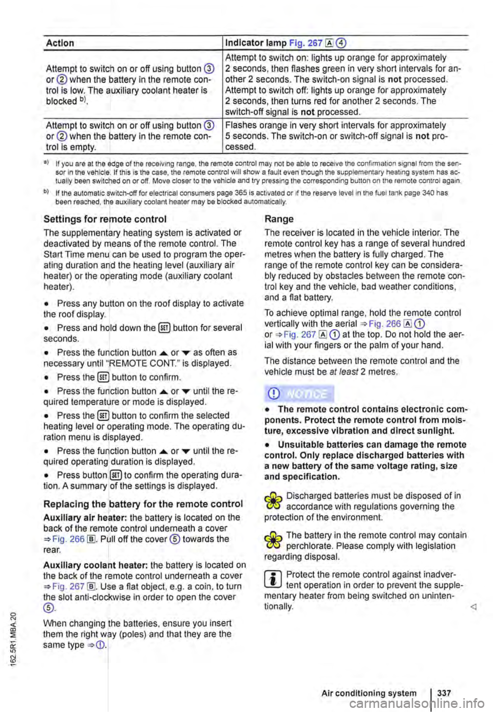
Action Indicator lamp Fig. 267
Attempt to switch on: lights up orange for approximately Attempt to switch on or off using button @ or@ when the battery in the remote con-trol is low. The auxiliary coolant heater is blocked bl.
2 seconds, then flashes green in very short intervals for an-other 2 seconds. The switch-on signal is not processed. Attempt to switch off: lights up orange for approximately 2 seconds, then turns red for another 2 seconds. The switch-off signal is not processed.
Attempt to switch on or off using button @ or@ when the battery in the remote con-trol is empty.
Flashes orange in very short intervals for approximately 5 seconds. The switch-on or switch-off signal is not pro-cessed.
•> If you are at the edge of the receiving range, the remote control may not be able to receive the confirmation signal from the sen-sor in the vehicle. If this is the case, the remote control will show a fault even though the supplementary heating system has ac-tually been switched on or off. Move closer to the vehicle and try pressing the corresponding button on the remote control again.
b) If the automatic switch-off for electrical consumers page 365 is activated or if the reserve level in lhe fuel tank page 340 has been reached, the auxiliary coolant heater may be blocked automatically.
Settings for remote control
The supplementary heating system is activated or deactivated by means of the remote control. The Start Time menu can be used to program the oper-ating duration and the heating level (auxiliary air heater) or the operating mode (auxiliary coolant heater).
• Press any button on the roof display to activate the roof display.
• Press and hold down the (ill) button for several seconds.
• Press the function button ...... or ,... as often as necessary until "REMOTE CONT." is displayed.
• Press the (ill) button to confirm.
• Press the function button ...... or ,... until the re-quired temperature or mode is displayed.
• Press the (ill) button to confirm the selected heating level or operating mode. The operating du-ration menu is displayed.
• Press the function button ...... or ,... until the re-quired operating duration is displayed.
• Press button @)to confirm the operating dura-tion. A summary of the settings is displayed.
Replacing the battery for the remote control
Auxiliary air heater: the battery is located on the back of the remote control underneath a cover 266 [ID. Pull off the cover® towards the rear.
Auxiliary coolant heater: the battery is located on the back of the remote control underneath a cover 267 [ID. Use a flat object, e.g. a coin, to turn the slot anti-clockwise in order to open the cover
®-
When changing the batteries, ensure you insert them the right way (poles) and that they are the same type
Range
The receiver is located in the vehicle interior. The remote control key has a range of several hundred metres when the battery is fully charged. The range of the remote control key can be considera-bly reduced by obstacles between the remote con-trol key and the vehicle, bad weather conditions, and a flat battery.
To achieve optimal range, hold the remote control vertically with the aerial 266 or 267 at the top. Do not hold the aer-ial with your fingers or the palm of your hand.
The distance between the remote control and the vehicle must be at least 2 metres.
CD
• The remote control contains electronic com-ponents. Protect the remote control from mois-ture, excessive vibration and direct sunlight.
• Unsuitable batteries can damage the remote control. Only replace discharged batteries with a new battery of the same voltage rating, size and specification.
Discharged batteries must be disposed of in W accordance with regulations governing the protection of the environment.
The battery in the remote control may contain W perchlorate. Please comply with legislation regarding disposal.
m Protect the remote control against inadver-L!.J tent operation in order to prevent the supple-mentary heater from being switched on uninten-
Air conditioning system I 337
Page 343 of 486
Capacities
r--('n First read and observe the introductory L-W.I information and safety warnings & on page 340.
Checks when filling the tank
r--r'n First read and observe the introductory L-W.I information and safety warnings & on page 340.
Checklist
Never carry out any work on the engine or in the engine compartment if you are not familiar with the necessary procedures and the general safety re-quirements or if the correct operating equipment, fluids and unsuitable tools are not available 350, Preparation for working in the engine compartment! The work should be carried out by a qualified workshop if you are uncertain. Please en-sure that the following are checked regular1y, pref-erably every time you fill the tank:
..( Windscreen washer fluid level 116
..( Engine oil level 353
Fuel
c:QJ Introduction
This chapter contains information on the following subjects:
Petrol
Diesel ...
344 345
Different engines require different fuels. The facto-ry-fitted sticker on the inside of the tank flap indi-cates the fuel type that is required for your particu-lar vehicle.
Volkswagen Commercial Vehicles recommends us-ing fuels with a low sulphur content or which are sulphur-free in order to reduce fuel consumption and prevent damage to the engine.
If the engine is not running smoothly or begins to judder, this can indicate poor or inadequate fuel quality, e.g. water in the fuel. If these symptoms appear, reduce the vehicle speed immediately and drive to the nearest qualified workshop at medium engine speeds, avoiding high engine loading. If these symptoms occur immediately after the vehi-
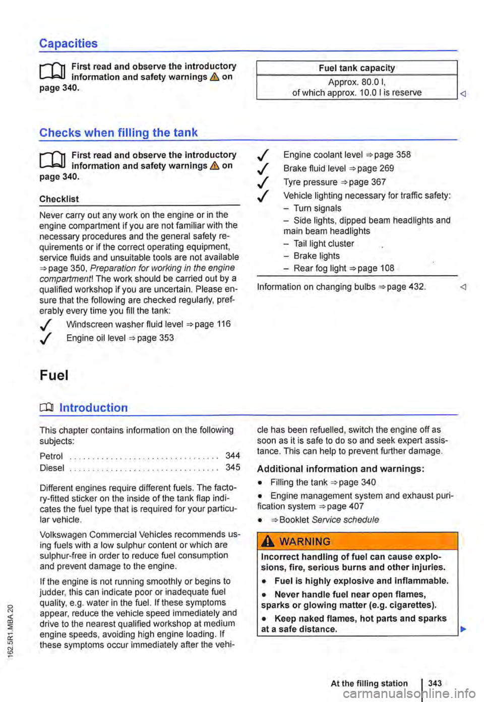
Fuel tank capacity
Approx. 80.0 I,
..( Engine coolant level 358
..( Brake fluid level 269
..( Tyre pressure 367
..( Vehicle lighting necessary for traffic safety:
-Turn signals
-Side lights, dipped beam headlights and main beam headlights
-Tail light cluster
-Brake lights
-Rear fog light 1 08
Information on changing bulbs 432.
cle has been refuelled, switch the engine off as soon as it is safe to do so and seek expert assis-tance. This can help to prevent further damage.
Additional information and warnings:
• Filling the tank 340
• Engine management system and exhaust puri-fication system 407
• Service schedule
A WARNING
Incorrect handling of fuel can cause explo-sions, fire, serious burns and other injuries.
• Fuel is highly explosive and inflammable.
• Never handle fuel near open flames, sparks or glowing matter (e.g. cigarettes).
• Keep naked flames, hot parts and sparks at a safe distance.
At the filling station 1343
Page 412 of 486
Making you and your vehicle safe
8S0.00)7
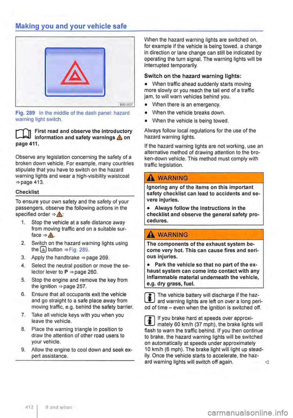
Fig. 289 In the middle of the dash panel: hazard warning light switch.
f"'""'('n First read and observe the Introductory L-lo:.U Information and safety warnings Lb. on page 411.
Observe any legislation concerning the safety of a broken down vehicle. For example, many countries stipulate that you have to switch on the hazard warning lights and wear a high-visibility waistcoat =>page 413.
Checklist
To ensure your own safety and the safety of your passengers, observe the following actions in the specified order => &:
1. Stop the vehicle at a safe distance away from moving traffic and on a suitable sur-face=>&.
2. Switch on the hazard warning lights using button =>Fig. 289.
3. Apply the handbrake =>page 269.
4. Select the neutral position or move the se-lector lever to P =>page 260.
5. Stop the engine and remove the key from the ignition =>page 257.
6. Ensure that all occupants exit the vehicle and go straight to a safe place away from moving traffic, e.g. behind the safety barrier.
7. Take all vehicle keys with you when you leave the vehicle.
8. Place the warning triangle in position to draw the attention of other road users to your vehicle.
9. Allow the engine to cool down and seek ex-pert assistance.
4121 If and when
When the hazard warning lights are switched on, for example if the vehicle is being towed, a change in direction or lane change can still be indicated by operating the turn signal. The warning lights will be interrupted temporarily.
Switch on the hazard warning lights:
• When traffic ahead suddenly starts moving more slowly or you reach the tail end of a traffic jam, to will warn vehicles behind you.
• When there is an emergency.
• When the vehicle breaks down.
• When the vehicle is being towed.
Always follow local regulations for the use of the hazard warning lights.
If the hazard warning lights are not working, use an alternative method of drawing attention to the bro-ken-down vehicle. This method must comply with traffic legislation.
A WARNING
Ignoring any of the items on this important safety checklist can lead to accidents and se-vere Injuries.
• Always follow the Instructions In the checklist and observe the general safety pro-cedures.
A wARNING
The components of the exhaust system be-come very hot. This can cause fires and seri-ous Injuries.
• Park the vehicle so that no part of the ex-haust system can come Into contact with any Inflammable material underneath the vehicle, e.g. dry grass, fuel.
m The vehicle battery will discharge if the haz-L.:!J ard warning lights are left on over a long peri-od of time -even when the Ignition is switched off.
m If you brake hard at speeds over approxi-L.:!J mately 60 km/h (37 mph), the brake lights will flash to warn the traffic behind. If you then continue to brake, the hazard warning lights will be switched on automatically at speeds under approximately 10 km/h (6 mph). The brake light will light up stead-Ily. Once the vehicle starts to accelerate, the haz-ard warning lights will switch off again.
Page 413 of 486
First aid kit, warning triangle, high-visibility waistcoat and fire
extinguisher
l"'""'('n First read and observe the introductory L.-J,::,JI Information and safety warnings & on page 411.
High-visibility waistcoat
In some vehicles there is a stowage compartment for a high-visibility waistcoat in the driver door 9.
Warning triangle
The warning triangle must comply with legal re-quirements.
First aid kit
The first aid kit must comply with legal require-ments. Comply with the expiry dates of the con-tents.
In some vehicles, there is a bag containing the warning triangle and first aid kit next to the vehicle toolkit.
To remove the bag, pull it inwards by the long end at the front while turning it downwards slightly.
Manual opening and closing
COl Introduction
This chapter contains information on the following subjects:
Unlocking the driver door manually . . . . . . . . . 414 Unlocking the tailgate manually ............ 414
Closing the sliding/tilting roof manually . . . . . 415
Unlocking the selector lever lock manually . . . 415
Should the radio signal of the remote control key or the central locking system fails, the doors, tailgate and sliding/tilting roof can be locked and, with some exceptions, unlocked manually.
Additional information and warnings:
• Vehicle key set 36
• Central locking system 39
• Doors 45
• Tailgate 49
• Sliding/tilting roof 58
• Closing the electric pop-up roof manually, Cali-fornia 192
In vehicles with a kitchenette, the first aid kit is lo-cated on the rear panel of the left stowage com-partment in the kitchen unit.
Fire extinguisher
Before using the fire extinguisher, make sure you are familiar with its operation. If an operating man-ual is supplied with the fire extinguisher, place it in the vehicle wallet.
The fire extinguisher must comply with the valid legal requirements. lt must be fully functional and checked regularly. See the test certificate on the fire extinguisher.
A WARNING
In the event of a sudden driving or braking manoeuvre or accident, loose objects could be flung though the vehicle and cause severe Injuries.
• Always secure the fire extinguisher, high-visibility waistcoat, first aid kit and warning triangle safely In the holders.
• In an emergency 411
A WARNING
Careless manual opening and closing can cause serious Injury.
• If the vehicle Is locked from the outside, the doors and windows cannot be opened from the inside.
• Never leave children or people requiring assistance alone In the vehicle. They could become trapped In the vehicle In an emergen-cy and may not be able to get themselves to safety.
• Temperatures Inside a locked vehicle may reach extremes of heat or cold, according to season. This can cause serious Injuries and Illness or fatalities, especially to small chil-dren. .,.
Practical tips 413
Page 432 of 486
Detecting a blown fuse
If the metal strip is melted this indicates that the fuse has blown 305.
Shine a torch onto the fuse. This will help you to spot the blown fuse more easily.
Changing a fuse
• If applicable, take the plastic pliers 306 G) out of the fuse box cover.
• For small fuses. push the catch on G) from above 306
• For larger fuses, push the catch G) onto the fuse from the side 306@
Changing bulbs
o::n Introduction
This chapter contains information on the following subjects:
Indicator lamp . . . . . . . . . . . . . . . . . . . . . . . . . 433
Information on changing bulbs . 433 LED lights on the vehicle . . . . . . . . . 434
Changing bulbs in H4 halogen headlights 435
Changing bulbs in H7 halogen headlights . . . 437
Changing bulbs in the LED headlights . . . 438
Changing the bulbs in the fog light . . . . . . . . . 439 Changing the bulbs in the tail light cluster on vehicles with tailgate . . . . . . . . . . . . . . . . . . . . . 440
Changing the bulbs in the tail light cluster on vehicles with wing doors .................. 441
Changing the bulbs in the LED tail light cluster . . . . . . . . . . . . . . . . . . . . . . . . . 442 Changing the side turn signal bulbs . . . . . . . . 443
Changing the vehicle bulbs requires considerable technical skill. Therefore if you do not feel confi-dent with the procedure. Volkswagen Commercial Vehicles recommends having the bulbs changed by a Volkswagen Commercial Vehicles dealership or other professional assistance. You must contact a qualified workshop if other vehicle parts around the lights need to be removed or LED lights need to be replaced.
You should keep a box with spare light bulbs for the lights that ensure the vehicle is roadworthy in the vehicle at all times. Spare bulbs are available from Volkswagen Commercial Vehicles dealers. In some countries it is a legal requirement to have these spare bulbs in the vehicle.
lt may be illegal to drive with a defective bulb in the exterior lighting.
4321 If and when
• Pull out the blown fuse.
• If the fuse has blown, replace it with a new fuse of the same amp rating (same colour and same markings) and same size
• Replace the cover.
CD
You can damage another position In the electri-cal system by using a fuse with a higher amp rating.
You can change the following bulbs yourself:
• Bulbs of the halogen headlights.
• Turn signal bulb in the LED headlights.
• Bulbs in non-LED tail light cluster.
• Turn signal and reversing light bulb in the LED tail light cluster.
• Bulb of turn signal repeater.
• Bulb of fog lights.
All LED lights in the vehicle should always be changed by an expert.
Additional bulb specifications
Some bulbs in headlights or In tail light clusters might have factory specifications that are different to standard bulbs. The designation is inscribed on the bulb, either on the glass part or on the base.
Additional information and warnings:
• Exterior views 5
• Lights and vision 106
• Preparation for working In the engine compart-ment 350
• Vehicle toolkit 416
• Fuses 429
A WARNING
Accidents can occur If roads are not suffi-ciently Illuminated and other road users have difficulty seeing the vehicle, or cannot see it atall. 11>
Page 434 of 486
Checklist (Continued)
3. Turn the light switch to position o 106.
4. Shift the tu m signal lever to neutral 106.
5. With a DSG® dual clutch gearbox, move the selector lever to position P 260.
6. Manual gearbox: select a gear 263.
7. Stop the engine and remove the key from the ignition 257.
8. Switch off the orientation lighting 106.
9. Leave the defective bulbs to cool down.
10. Check to see if a fuse has blown 429.
11. Follow the instructions to change the affec-ted bulb Always use identical bulbs of the same type. The designation is inscribed on the bulb, either on the glass part or on the base.
12. Do not touch the glass part of the bulb with unprotected fingers. The heat of the bulb would cause the fingerprint to evaporate and condense on the renector. This will im-pair the brightness of the headlight.
LED lights on the vehicle
r--f'n First read and observe the introductory L-I=J.I information and safety warnings & on page 432.
Depending on the vehicle equipment, the following lights may be LED lights:
• Dipped beam, main beam, daytime running lights and side lights on vehicles with LED head-lights.
• Tail light, brake light and fog light on vehicles with LED tail lights.
• Number plate lights.
434 If and when
13. After changing the bulb, check to ensure that the bulb is working properly. If the bulb is not working properly, the bulb may not have been inserted properly or may have failed again, or the connector may have been inserted incorrectly.
14. Any time you change a bulb in the front of the vehicle, the headlight settings should be checked by a qualified workshop.
A WARNING
Ignoring any of the items on this important safety checklist can lead to accidents and se-vere Injuries.
• Always follow the instructions in the checklist and observe the general safety pro-cedures.
CD
Always take care when removing or fitting lights in order to prevent damage to the paint-work or to other vehicle parts. <1
Owners cannot replace the LEDs themselves. If some LEDs fail, this may be an indication that more elements are on the point of failure. If this happens, have the lights checked and replaced if necessary at a qualified workshop.