set clock VOLKSWAGEN UP! 2021 Owner´s Manual
[x] Cancel search | Manufacturer: VOLKSWAGEN, Model Year: 2021, Model line: UP!, Model: VOLKSWAGEN UP! 2021Pages: 211, PDF Size: 5.98 MB
Page 10 of 211
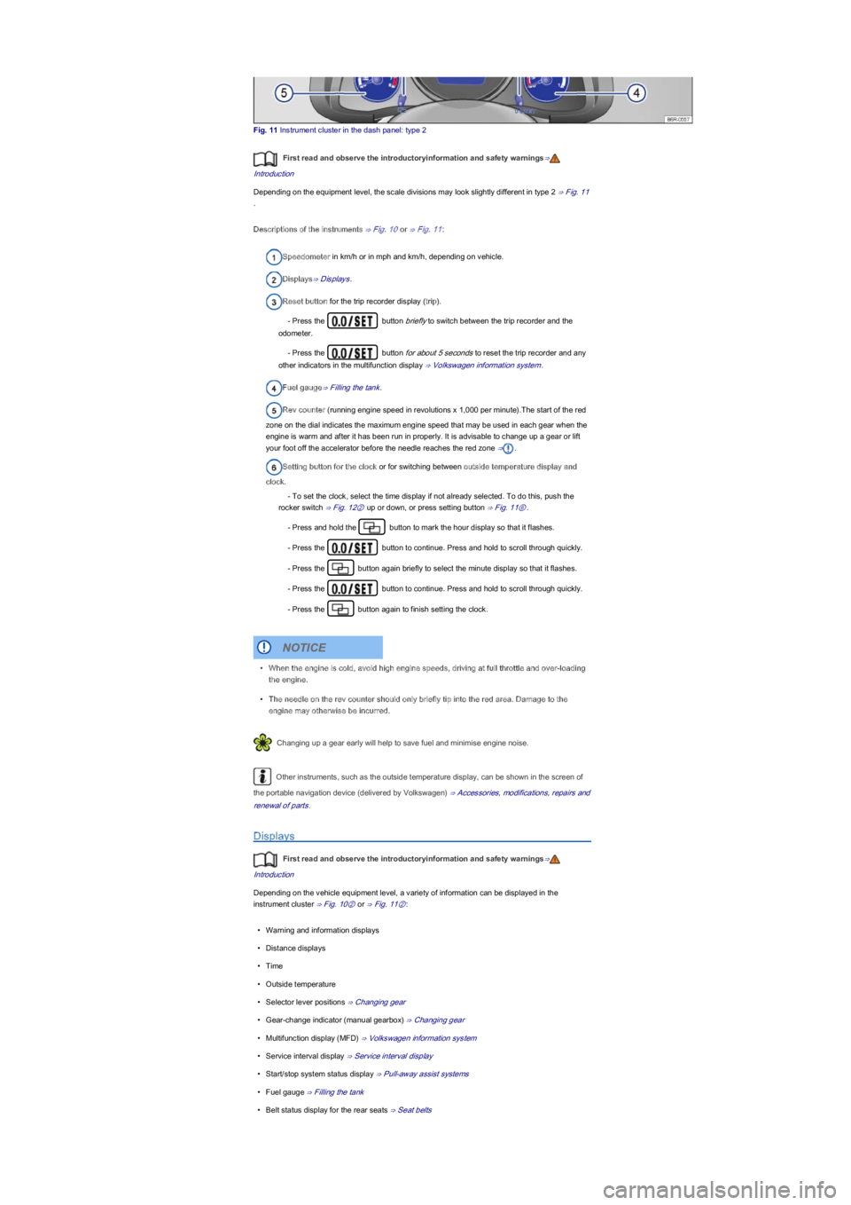
Fig. 11 Instrument cluster in the dash panel: type 2
First read and observe the introductoryinformation and safety warnings⇒
Introduction
Depending on the equipment level, the scale divisions may look slightly different in type 2 ⇒ Fig. 11
.
Descriptions of the instruments ⇒ Fig. 10 or ⇒ Fig. 11:
Speedometer in km/h or in mph and km/h, depending on vehicle.
Displays⇒ Displays.
Reset button for the trip recorder display (trip).
- Press the button briefly to switch between the trip recorder and the
odometer.
- Press the button for about 5 seconds to reset the trip recorder and any
other indicators in the multifunction display ⇒ Volkswagen information system.
Fuel gauge⇒ Filling the tank.
Rev counter (running engine speed in revolutions x 1,000 per minute).The start of the red
zone on the dial indicates the maximum engine speed that may be used in each gear when the
engine is warm and after it has been run in properly. It is advisable to change up a gear or lift
your foot off the accelerator before the needle reaches the red zone ⇒.
Setting button for the clock or for switching between outside temperature display and
clock.
- To set the clock, select the time display if not already selected. To do this, push the
rocker switch ⇒ Fig. 12② up or down, or press setting button ⇒ Fig. 11⑥.
- Press and hold the button to mark the hour display so that it flashes.
- Press the button to continue. Press and hold to scroll through quickly.
- Press the button again briefly to select the minute display so that it flashes.
- Press the button to continue. Press and hold to scroll through quickly.
- Press the button again to finish setting the clock.
Changing up a gear early will help to save fuel and minimise engine noise.
Other instruments, such as the outside temperature display, can be shown in the screen of
the portable navigation device (delivered by Volkswagen) ⇒ Accessories, modifications, repairs and
renewal of parts.
Displays
First read and observe the introductoryinformation and safety warnings⇒
Introduction
Depending on the vehicle equipment level, a variety of information can be displayed in the
instrument cluster ⇒ Fig. 10② or ⇒ Fig. 11②:
•Warning and information displays
•Distance displays
•Time
•Outside temperature
•Selector lever positions ⇒ Changing gear
•Gear-change indicator (manual gearbox) ⇒ Changing gear
•Multifunction display (MFD) ⇒ Volkswagen information system
•Service interval display ⇒ Service interval display
•Start/stop system status display ⇒ Pull-away assist systems
•Fuel gauge ⇒ Filling the tank
•Belt status display for the rear seats ⇒ Seat belts
•When the engine is cold, avoid high engine speeds, driving at full throttle and over-loading
the engine.
•The needle on the rev counter should only briefly tip into the red area. Damage to the
engine may otherwise be incurred.
NOTICE
Page 14 of 211
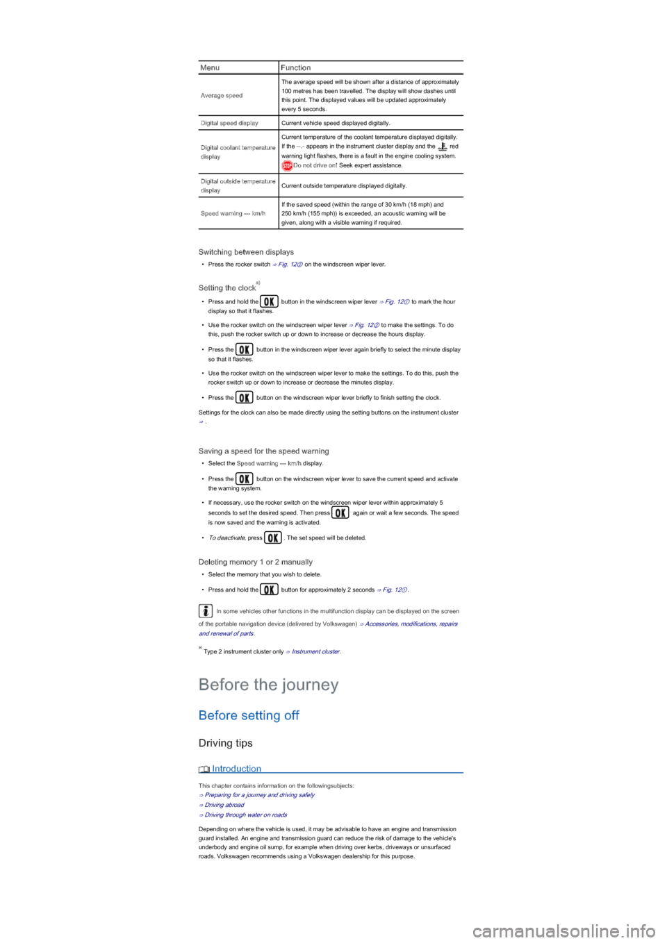
MenuFunction
Average speed
The average speed will be shown after a distance of approximately
100 metres has been travelled. The display will show dashes until
this point. The displayed values will be updated approximately
every 5 seconds.
Digital speed displayCurrent vehicle speed displayed digitally.
Digital coolant temperature
display
Current temperature of the coolant temperature displayed digitally.
If the --.- appears in the instrument cluster display and the red
warning light flashes, there is a fault in the engine cooling system.
Do not drive on! Seek expert assistance.
Digital outside temperature
displayCurrent outside temperature displayed digitally.
Speed warning --- km/h
If the saved speed (within the range of 30 km/h (18 mph) and
250 km/h (155 mph)) is exceeded, an acoustic warning will be
given, along with a visible warning if required.
Switching between displays
•Press the rocker switch ⇒ Fig. 12② on the windscreen wiper lever.
Setting the clock
•Press and hold the button in the windscreen wiper lever ⇒ Fig. 12① to mark the hour
display so that it flashes.
•Use the rocker switch on the windscreen wiper lever ⇒ Fig. 12② to make the settings. To do
this, push the rocker switch up or down to increase or decrease the hours display.
•Press the button in the windscreen wiper lever again briefly to select the minute display
so that it flashes.
•Use the rocker switch on the windscreen wiper lever to make the settings. To do this, push the
rocker switch up or down to increase or decrease the minutes display.
•Press the button on the windscreen wiper lever briefly to finish setting the clock.
Settings for the clock can also be made directly using the setting buttons on the instrument cluster
⇒ .
Saving a speed for the speed warning
•Select the Speed warning --- km/h display.
•Press the button on the windscreen wiper lever to save the current speed and activate
the warning system.
•If necessary, use the rocker switch on the windscreen wiper lever within approximately 5
seconds to set the desired speed. Then press again or wait a few seconds. The speed
is now saved and the warning is activated.
•To deactivate, press . The set speed will be deleted.
Deleting memory 1 or 2 manually
•Select the memory that you wish to delete.
•Press and hold the button for approximately 2 seconds ⇒ Fig. 12①.
In some vehicles other functions in the multifunction display can be displayed on the screen
of the portable navigation device (delivered by Volkswagen) ⇒ Accessories, modifications, repairs
and renewal of parts.
Type 2 instrument cluster only ⇒ Instrument cluster.
Before setting off
Driving tips
Introduction
This chapter contains information on the followingsubjects:
⇒ Preparing for a journey and driving safely
⇒ Driving abroad
⇒ Driving through water on roads
Depending on where the vehicle is used, it may be advisable to have an engine and transmission
guard installed. An engine and transmission guard can reduce the risk of damage to the vehicle's
underbody and engine oil sump, for example when driving over kerbs, driveways or unsurfaced
roads. Volkswagen recommends using a Volkswagen dealership for this purpose.
a)
a)
Before the journey
Page 127 of 211
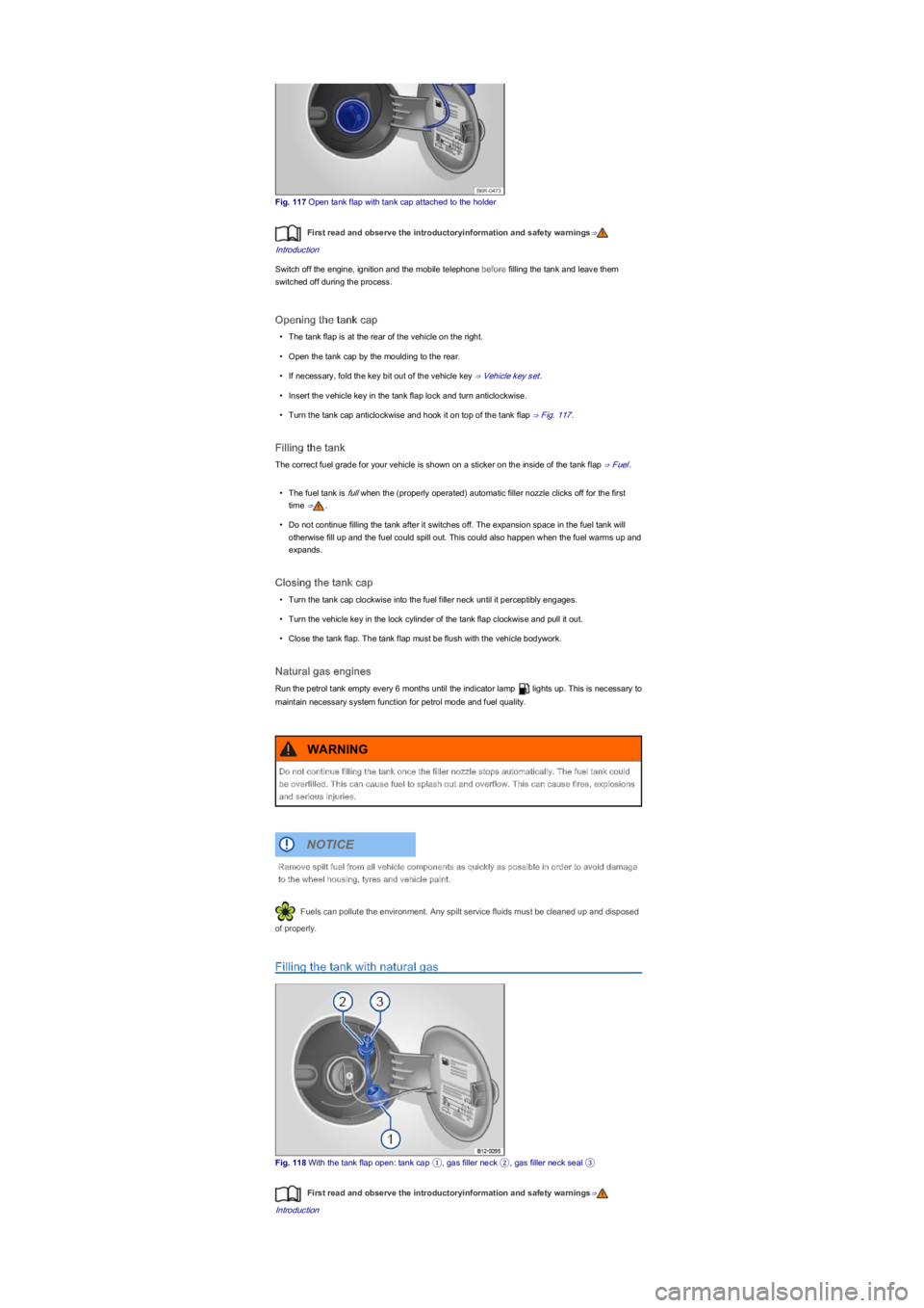
Fig. 117 Open tank flap with tank cap attached to the holder
First read and observe the introductoryinformation and safety warnings⇒
Introduction
Switch off the engine, ignition and the mobile telephone before filling the tank and leave them
switched off during the process.
Opening the tank cap
•The tank flap is at the rear of the vehicle on the right.
•Open the tank cap by the moulding to the rear.
•If necessary, fold the key bit out of the vehicle key ⇒ Vehicle key set.
•Insert the vehicle key in the tank flap lock and turn anticlockwise.
•Turn the tank cap anticlockwise and hook it on top of the tank flap ⇒ Fig. 117.
Filling the tank
The correct fuel grade for your vehicle is shown on a sticker on the inside of the tank flap ⇒ Fuel.
•The fuel tank is full when the (properly operated) automatic filler nozzle clicks off for the first
time ⇒.
•Do not continue filling the tank after it switches off. The expansion space in the fuel tank will
otherwise fill up and the fuel could spill out. This could also happen when the fuel warms up and
expands.
Closing the tank cap
•Turn the tank cap clockwise into the fuel filler neck until it perceptibly engages.
•Turn the vehicle key in the lock cylinder of the tank flap clockwise and pull it out.
•Close the tank flap. The tank flap must be flush with the vehicle bodywork.
Natural gas engines
Run the petrol tank empty every 6 months until the indicator lamp lights up. This is necessary to
maintain necessary system function for petrol mode and fuel quality.
Fuels can pollute the environment. Any spilt service fluids must be cleaned up and disposed
of properly.
Filling the tank with natural gas
Fig. 118 With the tank flap open: tank cap ①, gas filler neck ②, gas filler neck seal ③
First read and observe the introductoryinformation and safety warnings⇒
Introduction
Do not continue filling the tank once the filler nozzle stops automatically. The fuel tank could
be overfilled. This can cause fuel to splash out and overflow. This can cause fires, explosions
and serious injuries.
WARNING
Remove spilt fuel from all vehicle components as quickly as possible in order to avoid damage
to the wheel housing, tyres and vehicle paint.
NOTICE
Page 185 of 211
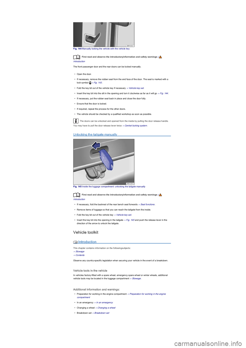
Fig. 144 Manually locking the vehicle with the vehicle key
First read and observe the introductoryinformation and safety warnings⇒
Introduction
The front passenger door and the rear doors can be locked manually.
•Open the door.
•If necessary, remove the rubber seal from the end face of the door. The seal is marked with a
lock symbol ⇒ Fig. 143.
•Fold the key bit out of the vehicle key if necessary ⇒ Vehicle key set.
•Insert the key bit into the slit in the opening and turn it clockwise as far as it will go ⇒ Fig. 144.
•If necessary, put the rubber seal back in place and close the door fully.
•Ensure that the door is locked.
•If required, repeat the process for the other doors.
•The vehicle should be checked by a qualified workshop as soon as possible.
The doors can be unlocked and opened from the inside by pulling the door release handle.
You may have to pull the door release lever twice ⇒ Central locking system.
Unlocking the tailgate manually
Fig. 145 Inside the luggage compartment: unlocking the tailgate manually
First read and observe the introductoryinformation and safety warnings⇒
Introduction
•If necessary, fold the backrest of the rear bench seat forwards ⇒ Seat functions.
•Remove items of luggage so that you can reach the tailgate from the inside.
•Fold the key bit out of the vehicle key ⇒ Vehicle key set.
•Insert the key bit into the opening in the tailgate ⇒ Fig. 145 and push the release lever in the
direction of the arrow to unlock the tailgate.
Vehicle toolkit
Introduction
This chapter contains information on the followingsubjects:
⇒ Stowage
⇒ Contents
Observe any country-specific legislation when securing your vehicle in the event of a breakdown.
Vehicle tools in the vehicle
In vehicles factory-fitted with a spare wheel, emergency spare wheel or winter wheels, additional
vehicle tools may be located in the luggage compartment ⇒ Stowage.
Additional information and warnings:
•Preparation for working in the engine compartment ⇒ Preparation for working in the engine
compartment
•In an emergency ⇒ In an emergency
•Changing a wheel ⇒ Changing a wheel
•Breakdown set ⇒ Breakdown set
Page 190 of 211
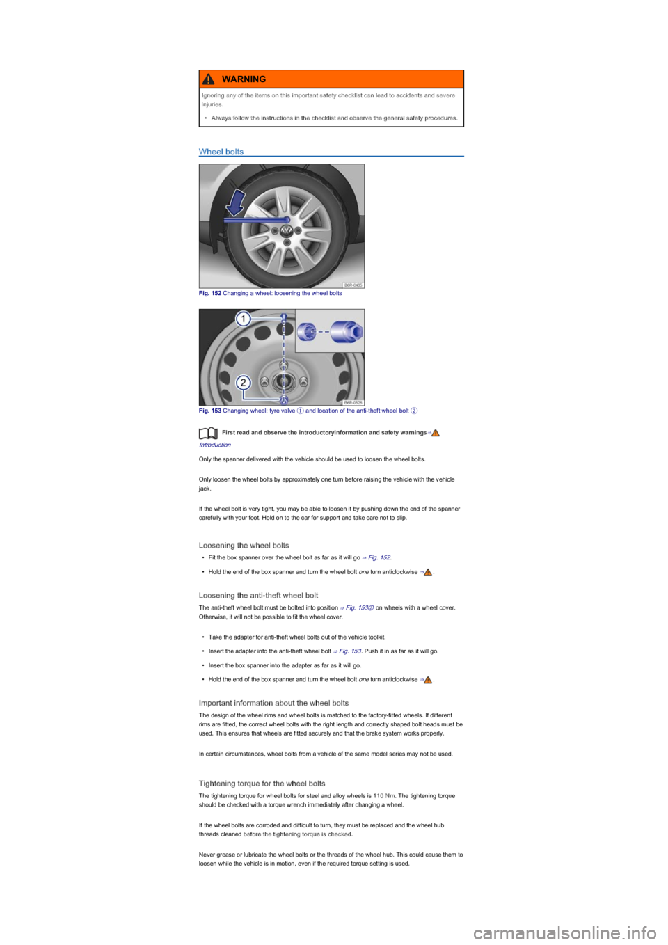
Wheel bolts
Fig. 152 Changing a wheel: loosening the wheel bolts
Fig. 153 Changing wheel: tyre valve ① and location of the anti-theft wheel bolt ②
First read and observe the introductoryinformation and safety warnings⇒
Introduction
Only the spanner delivered with the vehicle should be used to loosen the wheel bolts.
Only loosen the wheel bolts by approximately one turn before raising the vehicle with the vehicle
jack.
If the wheel bolt is very tight, you may be able to loosen it by pushing down the end of the spanner
carefully with your foot. Hold on to the car for support and take care not to slip.
Loosening the wheel bolts
•Fit the box spanner over the wheel bolt as far as it will go ⇒ Fig. 152.
•Hold the end of the box spanner and turn the wheel bolt one turn anticlockwise ⇒.
Loosening the anti-theft wheel bolt
The anti-theft wheel bolt must be bolted into position ⇒ Fig. 153② on wheels with a wheel cover.
Otherwise, it will not be possible to fit the wheel cover.
•Take the adapter for anti-theft wheel bolts out of the vehicle toolkit.
•Insert the adapter into the anti-theft wheel bolt ⇒ Fig. 153. Push it in as far as it will go.
•Insert the box spanner into the adapter as far as it will go.
•Hold the end of the box spanner and turn the wheel bolt one turn anticlockwise ⇒.
Important information about the wheel bolts
The design of the wheel rims and wheel bolts is matched to the factory-fitted wheels. If different
rims are fitted, the correct wheel bolts with the right length and correctly shaped bolt heads must be
used. This ensures that wheels are fitted securely and that the brake system works properly.
In certain circumstances, wheel bolts from a vehicle of the same model series may not be used.
Tightening torque for the wheel bolts
The tightening torque for wheel bolts for steel and alloy wheels is 110 Nm. The tightening torque
should be checked with a torque wrench immediately after changing a wheel.
If the wheel bolts are corroded and difficult to turn, they must be replaced and the wheel hub
threads cleaned before the tightening torque is checked.
Never grease or lubricate the wheel bolts or the threads of the wheel hub. This could cause them to
loosen while the vehicle is in motion, even if the required torque setting is used.
Ignoring any of the items on this important safety checklist can lead to accidents and severe
injuries.
•Always follow the instructions in the checklist and observe the general safety procedures.
WARNING
Page 195 of 211
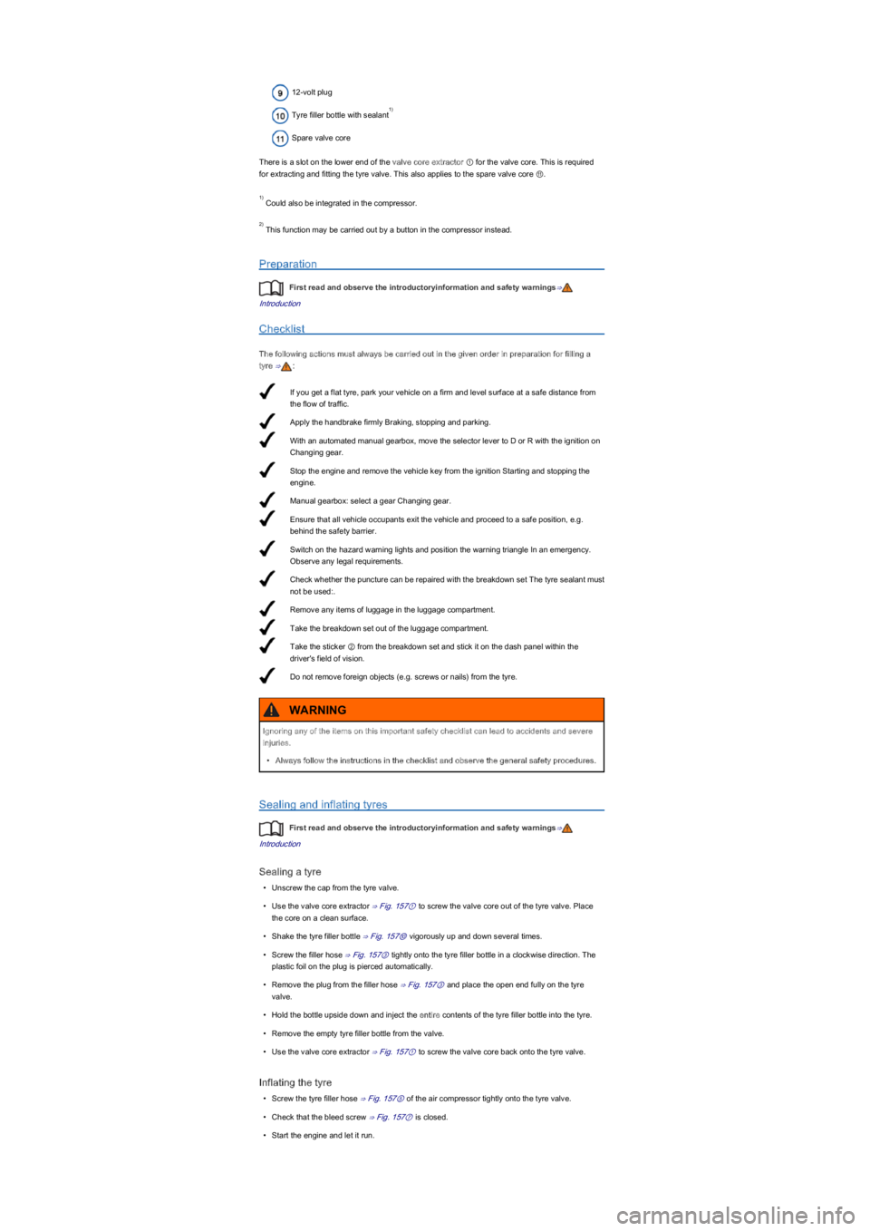
If you get a flat tyre, park your vehicle on a firm and level surface at a safe distance from
the flow of traffic.
Apply the handbrake firmly Braking, stopping and parking.
With an automated manual gearbox, move the selector lever to D or R with the ignition on
Changing gear.
Stop the engine and remove the vehicle key from the ignition Starting and stopping the
engine.
Manual gearbox: select a gear Changing gear.
Ensure that all vehicle occupants exit the vehicle and proceed to a safe position, e.g.
behind the safety barrier.
Switch on the hazard warning lights and position the warning triangle In an emergency.
Observe any legal requirements.
Check whether the puncture can be repaired with the breakdown set The tyre sealant must
not be used:.
Remove any items of luggage in the luggage compartment.
Take the breakdown set out of the luggage compartment.
Take the sticker ② from the breakdown set and stick it on the dash panel within the
driver's field of vision.
Do not remove foreign objects (e.g. screws or nails) from the tyre.
12-volt plug
Tyre filler bottle with sealant
Spare valve core
There is a slot on the lower end of the valve core extractor ① for the valve core. This is required
for extracting and fitting the tyre valve. This also applies to the spare valve core ⑪.
Could also be integrated in the compressor.
This function may be carried out by a button in the compressor instead.
Preparation
First read and observe the introductoryinformation and safety warnings⇒
Introduction
Checklist
The following actions must always be carried out in the given order in preparation for filling a
tyre ⇒:
Sealing and inflating tyres
First read and observe the introductoryinformation and safety warnings⇒
Introduction
Sealing a tyre
•Unscrew the cap from the tyre valve.
•Use the valve core extractor ⇒ Fig. 157① to screw the valve core out of the tyre valve. Place
the core on a clean surface.
•Shake the tyre filler bottle ⇒ Fig. 157⑩ vigorously up and down several times.
•Screw the filler hose ⇒ Fig. 157③ tightly onto the tyre filler bottle in a clockwise direction. The
plastic foil on the plug is pierced automatically.
•Remove the plug from the filler hose ⇒ Fig. 157③ and place the open end fully on the tyre
valve.
•Hold the bottle upside down and inject the entire contents of the tyre filler bottle into the tyre.
•Remove the empty tyre filler bottle from the valve.
•Use the valve core extractor ⇒ Fig. 157① to screw the valve core back onto the tyre valve.
Inflating the tyre
•Screw the tyre filler hose ⇒ Fig. 157⑤ of the air compressor tightly onto the tyre valve.
•Check that the bleed screw ⇒ Fig. 157⑦ is closed.
•Start the engine and let it run.
1)
1)
2)
Ignoring any of the items on this important safety checklist can lead to accidents and severe
injuries.
•Always follow the instructions in the checklist and observe the general safety procedures.
WARNING