brakes VOLVO 960 1982 Service Repair Manual
[x] Cancel search | Manufacturer: VOLVO, Model Year: 1982, Model line: 960, Model: VOLVO 960 1982Pages: 168, PDF Size: 54.28 MB
Page 3 of 168
(
)
Contents
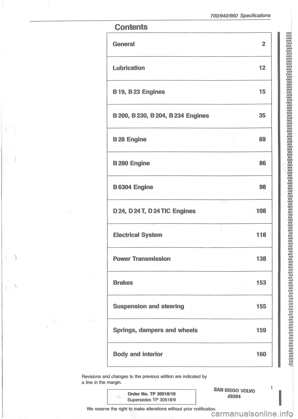
General
Lubrication B 19, B 23 Engines
B200, B230, B204, B234 Engines
B28 Engine
B280 Engine
B
6304 Engine
024, 024 T , 024 TIC Engines
Electrical System
Power Transmission
Brakes
Suspension and steering
Springs , dampers and
wheels
Body and interior
Revisions and changes to the previous edition are indicated by
a
line in the margin.
Order No. TP 30518/10
Supersedes TP 30518/9
70019401960 Specifications
'., ..
SAN DIEGO ~OLVO
tI5384
2
12
15
35
69 86
98
108
118
138
153 155
159
160
We reserve the right to make alterations without prior notification.
11111 1 1111 1111 IIII! 1111
11111 1111 1111 ·1111 1111 11111 1111 11111 1111 11111 1111 1111 1111
;::::::: 1111 1,1 ..... 1111 II,' ....
~:,:,:,: 1111 , ...... 1
1,' .... 1
1 ...... 1 1111 ·11" 1111 ,II', 1111 III'
I:':':':
'"' '"' ~ .... ,'. 1111 , .... " 1 III' 1111
:I:':',~ ·11 11,1
,"' 1111 III'
'" 1111 ...... 1 ,11' "'1 ,II'
"" I .... I~ III
"' "' ·111 1111 ,III
"' I II I
'" 1111
"' 1111
·11' 1111 I II 1 III III 11 .... 1 III 111/ ,II til. '"I III 1111 .'.'111 ,III 111/ ,II
11.'.'1
Itt'.'1
' llt
lit 'II It.'I'1 It.'.'1 III IItl 'II~ III III til "'1 " " , .... 11
'~I~'~
Page 8 of 168
I
70019401960 Specifications
Section 0 General
1
~-
'''''~''''.' .. ~. . . , .... -. . .~. ," _. , . ..... ,. . . . . VOLV o . '
VOLVO _._N
C I, c , ,. .. , . I
4 C 3
r--8280 9A 150 873
740,760 ,940 ,960
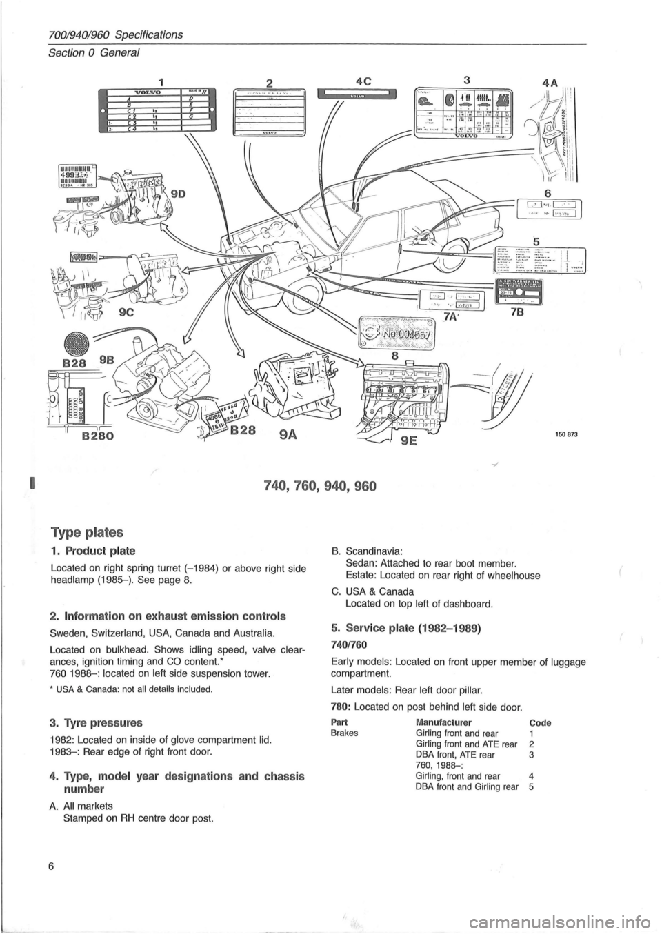
T ype p lates
1. P roduc t p la te
Located on right spring turret (-1984) or above right side
headlamp (1985-). See page 8.
2 . Inf ormation on exhau st emissio n co ntr ols
Sweden , Switzerland, USA, Canada and Australia.
Located on bulkhead. Shows idling speed, valve clear
ances, ignition timing and CO content. '
760 1988-: located on left side suspension tower.
* USA & Canada: not all details included .
3. Tyre p ress ures
1982 : Located on inside of glove compartment lid.
1983-: Rear edge of right front door.
4. Type, m ode l year des ig nat io ns a nd c hass is
numbe r
A. All markets
Stamped
on RH centre door post.
6
B. Scandinavia:
Sedan: Attached to rear boot member .
Estate: Located on rear right of
wheelhouse
C. USA & Canada
Located on top
left of dashboard.
5. Service pla te (1982-1 989 )
74 01760
Early models : Located on front upper member of luggage
compartment.
Later
models: Rear left door pillar.
780: Located on post behind left side door.
Part Brakes Manufactur er Girling front and rear Girling front and ATE rear
DBA front, ATE rear 760,1988-:
Code 1 2 3
Girling, front and rear 4
DBA front and Girling rear 5
(
Page 10 of 168
70019401960 Specifications
Section 0 General
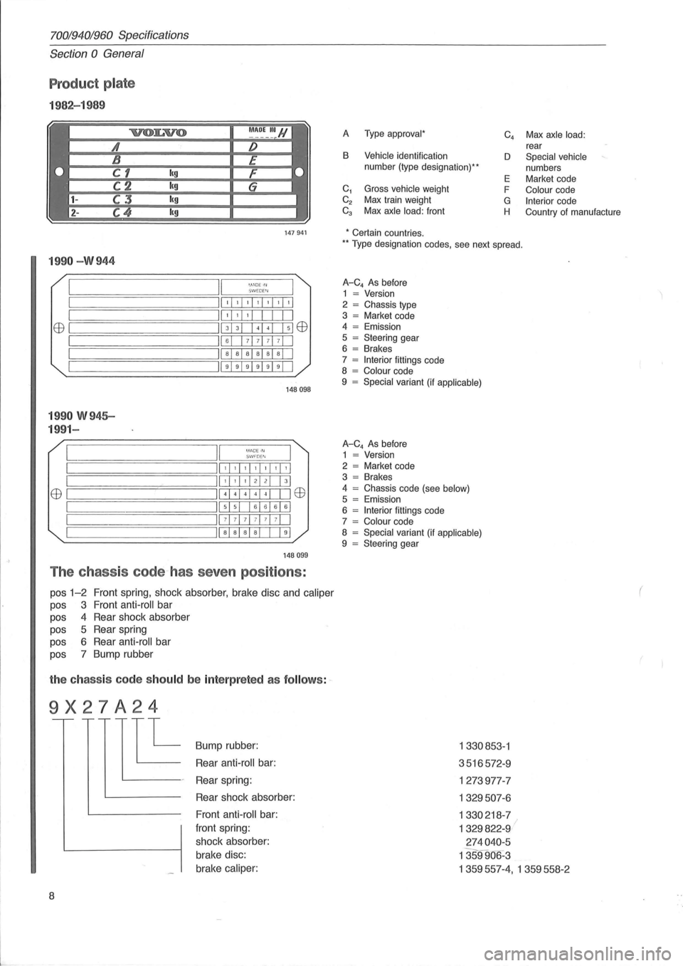
Product plate
1982-1 989
A Type approval *
B Vehicle identification
number (type designation) **
C
1 Gross vehicle weight
C
2 Max train weight Ca Max axle load: front C
4 Max axle
load: rear
D Special vehicle
numbers
E Market code
F
Colour code
G Interior code
H Country of manufacture
147941 * Certain countries.
199 0 -W 944
II '. 1.'DE Irl ~========:~===;:=:::;::;W::::,::::EW'::;:::::=r== ;==============ill, , , ,I, ,1'1 II' , , I I EEl ~===========;II 3 3 + El EEl
;==============ill 6 7 71 7 7 1 I II a a a al a al I ~===================; 11999919911
1 99 0 W 945-
199 1-
[ '.11'10E III S I.'/ FD E"I
148098
,I, ,1,1,1,1,1
EEl ~I ======== I
,I, ,I 21 21 I 31
41441414 1 I IEEl
515 161616161
71 7 7 1 71 71 71 I
Iiaia alai I 191
14 8099
The chass is code~has seven positions :
pos 1-2 Front spring, shock absorber, brake disc and caliper
pas 3 Front anti -roll bar
pas 4 Rear shock absorber
pas 5 Rear spring
pas 6 Rear anti -roll bar
pas 7 Bump rubber
the ch ass is code sh ould be inte rp reted as follow s: ~
9X27A24
E
8
Bump rubber:
Rear
anti -roll bar:
Rear spring:
Rear shock absorber:
Front
anti -roll bar:
front spring:
shock absorber:
brake disc:
brake
caliper:
** T ype designation codes, see next spread.
A-C4 As before
1 = Version
2 = Chassis type
3 = Market code
4 = Emission
5 = Steering gear
6 = Brakes
7 = Interior fittings code
8 = Colour code
9 = Special variant (if applicable)
A-C4 As before
1 = Version
2 = Market code
3 = Brakes
4
= Chassis code (see below) 5 = Emission
6 = Interior fittings code
7 = Colour code
8 = Special variant (if applicable) 9 = Steering gear
1330853 -1
3516572 -9
1273977-7
1329507 -6
1330218 -7
1329822-9 I
2 74040 -5
1359906 -3
1359557-4, 1359558- 2
(
Page 142 of 168
70019401960 Specifications
Section 4 Power Transmission
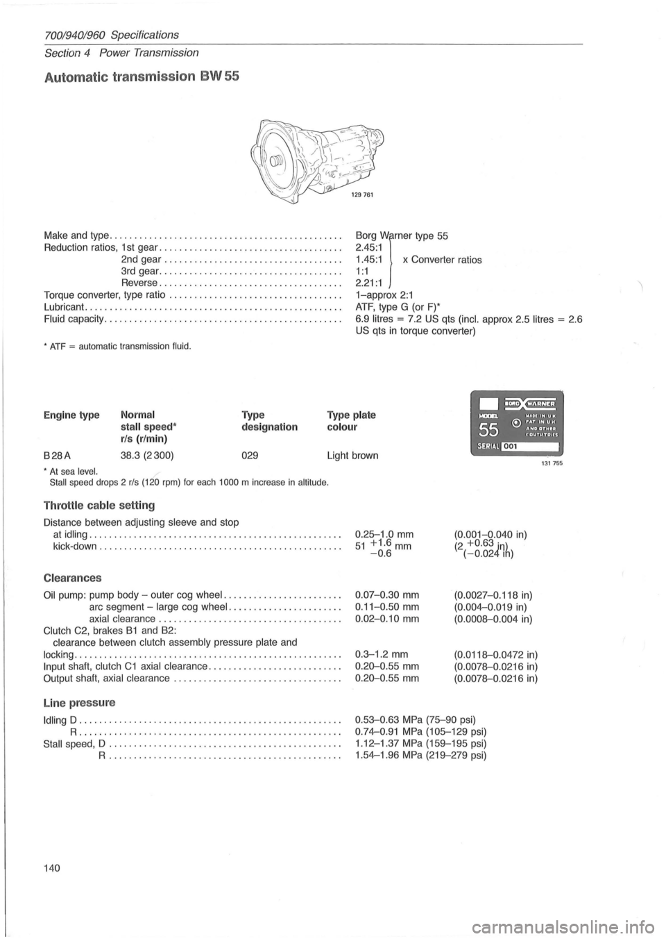
Automat ic transmission BW 55
Make and type .. ............................................ .
Reduction ratios, 1 st gear ..
................. ................. .
2nd gear
................................... .
3rd gear
................... ................. .
Reverse
.................................... .
Torque converter, type ratio
................................ .. .
Lubricant.
........................... ....................... .
Fluid capacity .................... ........................... .
* ATF = automatic transmission fluid.
1.45:1 x Converter ratios
Borg
Wirner type
55
2.45 :1
1 : 1
2.21 : 1
1-approx 2:1
ATF, type G (or F)*
6.9
litres = 7.2 US qts (inc!. approx 2.5 litres = 2 .6
US qts in torque converter)
.~ Engine type Normal
stall speed*
rls (r/min)
Type
designation
Type plate
colour
....... WAOIIHUH
55 e:> ~~D ~~~I~ f'"OUTUTAUS
B28A 38.3 (2300) 029 SERIAl~ Light brown 131755 * At sea level.
Stall speed drops 2 rls (120 rpm) for each 1000 m increase in altitude .
Throttle cable setting
Distance between adjusting sleeve and stop
at idling .................................................. .
kick -down
........................ ........................ .
C leara nces
Oil pump: pump body -outer cog wheel ....................... .
arc segment -
large cog wheel ...................... .
axial clearance .................................... .
Clutch C2, brakes B1 and B2:
clearance between
clutch assembly pressure plate and
locking ..................................................... .
Input shaft, clutch C1 axial clearance .......................... .
Output shaft,
axial clearance ................................. .
Line pressure
Idling D .................................................... .
R ..................... .... ........................... .
Stall speed, D .................. .............. ...... ........ .
R .............................................. .
140 0.25-1
.0
mm 51 +1.6mm -0.6
0.07-0.30 mm
0.11-0 .50 mm
0.02-0.10 mm
0.3-1 .2 mm
0.20-0 .55 mm
0.20-0.55 mm
(0.001-0.040 in) (2 +0.63 in) (-0.024Ih)
(0.0027-0.118 in)
(0.004-0 .019 in)
(0.0008-0.004 in)
(0.0118-0 .0472 in)
(0.0078-0.0216 in)
(0.0078-0.0216 in)
0.53-0.63 MPa (75-90 psi)
0.74-0.91 MPa (105-129 psi)
1 .12 -1.37
MPa (159-195 psi)
1.54-1.96
MPa (219-279 psi)
Page 145 of 168
(
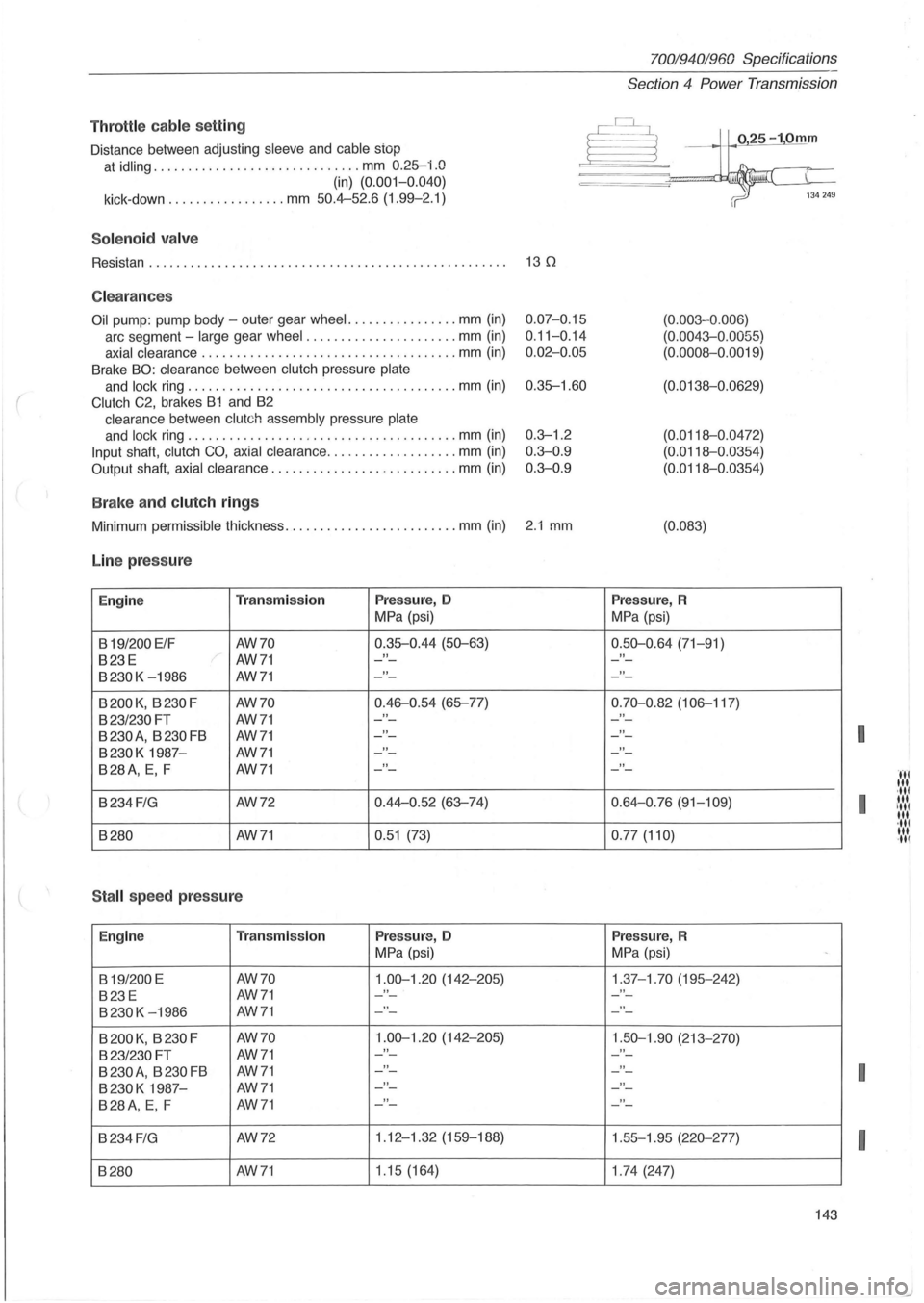
Throttl e cable se tting
Distance between adjusting sleeve and cable stop
at idling .............................. mm 0.25-i.O
(in) (0. 001-0.040)
kick-down ............. .... mm 50.4-52.6 (1.99-2.1)
Sol e n o id va lv e
Resistan . . . . . . . . . . . . . . . . . . . . . . . . . . . . . . . . . . . . . . . . . . . . . . . . . . . . 13 0
C lea ra n ces
Oil pump : pump body -outer gear wheel. ............... mm (in)
arc segment -large gear wheel ...................... mm (in)
axial clearance ................................ ..... mm (in)
Brake BO: clearance between clutch pressure plate
and lock ring ....................................... mm (in)
Clutch C2, brakes B1 and B2
clearance between clutch assembly pressure plate
and lock ring ....................................... mm (in)
Input shaft, clutch CO, axial clearance ........... ... ..... mm (in)
Output shaft, axial clearance ................. .......... mm (in)
B ra ke a nd clutch ring s
0.07-0.15
0 .
11-0.14
0 .
02-0.05
0.35-1.60
0.3--1.2
0 .
3--0.9
0.3--0 .9
Minimum permissible thickness ..................... .... mm (in) 2.1 mm
Line pr ess ure
Engine Tra nsmi ssion Press ure, 0
MPa (psi)
B
19/200 ElF AW70 0.35-0.44
(50--63)
B23E AW71 "
B230K -1986 AW71 "
B200K, B230F AW70 0.46-0.54 (65-77)
B23/230FT AW71 "
B 230 A
, B 230 FB AW71 "
B230K 1987-AW71 "
B28A, E, F AW71 "
B234 FIG AW72 0.44-0
.52 (63--74)
B280
AW71 0.51 (73)
S tall spee d press ure
Engine T
ra n smi ssion Press ure, 0
MPa (psi)
B
19/200 E AW70 1.00--1.20 (142-205)
B23E AW71 "
B230K -1986 AW71 "
B 200 K, B 230 F AW70 1.00--1.20 (142-205)
B23/230 FT AW71 "
B 230 A, B 230 FB AW71 "
B230K 1987-AW71 "
B28A, E, F AW71 "
B234 FIG AW72 1.12
-1.32 (159-188)
B280 AW71 1
.15 (164)
7001940 1960 Specifications
Section
4 Power Transmission
025-10mm
(0.003 -0 .006)
(0.0043--0 .0055)
(0.0008-0.0019)
(0.0138-0.0629)
(0.0118-0.0472)
(0.0118-0.0354)
(0.0118-0 .0354)
(0.083)
Pres sur e, R
MPa (psi)
0.50--0 .64 (71-91)
"
"
0.70--0.82 (106-117)
"
"
"
"
0.64-0.76 (91-109)
0 .
77 (110)
Press ure, R
MPa (psi)
1.37-1.70 (195-242) "
"
1.50--1.90 (213-270)
- -
"
"
"
1 .55-1.95 (220--277)
1 .
74 (247)
-
143
I
I
I
I
Page 155 of 168
70019401960 Specifications
Section
5 Brakes
Section 5 Brakes
fJy ~~
132426
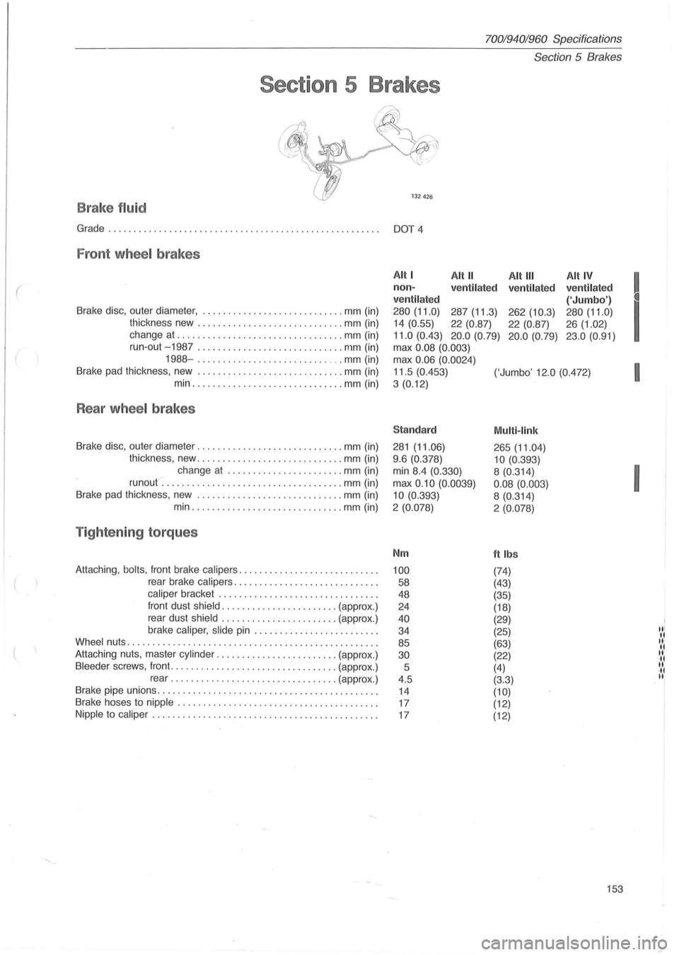
B rake fluid
Grade................................... .... ... ............ DOT 4
Fron t wheel brakes
(
Brake disc, outer diameter, .. .................... .. .... mm (in)
thickness new
............................ . mm (in)
change at
........ ........... .............. mm (in)
Alt I Alt" Alt III Alt IV
! non -
ve ntil ated
ve ntilat ed ventilated
ventil ated
('Jumbo')
I
280 (11.0) 287 (11.3) 262 (10.3) 280 (11.0)
14 (0.55)
22 (0.87)
22 (0.87) 26 (1.02)
11.0 (0.43) 20.0 (0.79) 20 .0 (0. 79) 23.0 (0.91)
run-out -1987 ... ....... .. ................. mm (in)
max 0.08 (0.003)
1988-.................. ........... mm (in)
Brake pad thickness, new .
............................ mm (in)
min
.... ............ ........... ... mm (in) max
0
.06 (0.0024)
I 11.5 (0.453)
('Jumbo' 12.0 (0.472)
3
(0. 12)
Rear wheel brakes
Sta ndard Multi -link
Brake disc, outer diameter ....... ...................... mm (in) 281 (11.06)
265 (11.04)
thickness, new ............................. mm (in)
change at
............... ........ mm (in)
runout .
...................... ............. mm (in)
Brake pad thickness , new .
..... ....... ............... . mm (in) 9
.6 (0.378)
10 (0.393)
I
min 8.4 (0.330) 8 (0.314)
max
0.10 (0.0039)
0.08 (0.003)
10
(0. 393)
8 (0.314)
min ............ .................. mm (in)
2 (0.078) 2 (0.078)
T ight enin g torque s
Nm ftlbs
Attaching , bolts , front brake calipers ........................... . 100 (74)
rear brake calipers ............................ .
58 (43)
caliper bracket ....................... ....... . .
48 (35)
front dust
shield .................... ... (approx .)
24 (18)
rear dust
shield ................ ....... (approx.)
brake
caliper, slide pin ................... ..... .
40 (29)
"I 34
(25) II Wheel nuts ................................................. .
85 (63) II II Attaching nuts, master cylinder ..... ................... (approx.) 30 (22) II II Bleeder screws, front ......................... ........ (approx .)
5 (4) II ·11 rear ...... .......... ................. (approx .)
4.5 (3.3) II
Brake pipe unions ...... .......... ............ ............... .
14 (10) Brake hoses to nipple ....................................... .
17 (12)
Nipple to caliper ......... ................................... .
17 (12)
153
Page 156 of 168
70019401960 Specifications
Section
5 Brakes
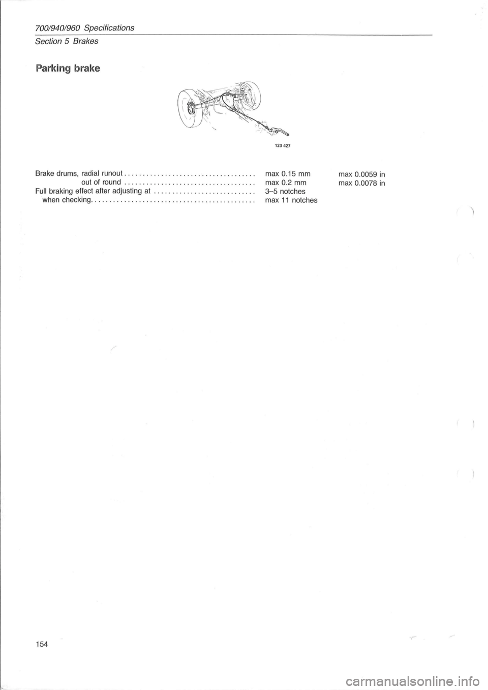
Parking brake
123427
Brake drums, radial runout . . . . . . . . . . . . . . . . . . . . . . . . . . . . . . . . . . . . max 0.15 mm
out of round . . . . . . . . . . . . . . . . . . . . . . . . . . . . . . . . . . . . max
0.2 mm
Full braking effect after adjusting at . . . . . . . . . . . . . . . . . . . . . . . . . . . . 3-5 notches
when checking. . . . . . . . . . . . . . . . . . . . . . . . . . . . . . . . . . . . . . . . . . . . . max
11 notches
154 max
0.0059 in
max 0.0078 in
-r