fuel VOLVO C30 2008 Owners Manual
[x] Cancel search | Manufacturer: VOLVO, Model Year: 2008, Model line: C30, Model: VOLVO C30 2008Pages: 234, PDF Size: 4.8 MB
Page 3 of 234
recalls43Transceiver (option)
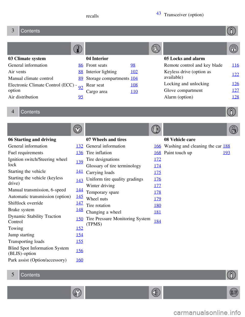
3 Contents
03 Climate system
General information86
Air vents88
Manual climate control89
Electronic Climate Control (ECC) -
option92
Air distribution
95
04 Interior
Front seats98
Interior lighting102
Storage compartments104
Rear seat108
Cargo area110
05 Locks and alarm
Remote control and key blade 116
Keyless drive (option as
available)122
Locking and unlocking
126
Glove compartment127
Alarm (option)128
4 Contents
06 Starting and driving
General information132
Fuel requirements136
Ignition switch/Steering wheel
lock139
Starting the vehicle
141
Starting the vehicle (keyless
drive)143
Manual transmission, 6-speed
144
Automatic transmission (option)145
Shiftlock override147
Brake system148
Dynamic Stability Traction
Control150
Towing
152
Jump starting154
Transporting loads155
Blind Spot Information System
(BLIS)-option156
Park assist (Option/accessory)
160
07 Wheels and tires
General information166
Tire inflation168
Tire designations172
Glossary of tire terminology174
Carrying loads175
Uniform tire quality gradings176
Winter driving177
Temporary spare178
Wheel nuts179
Tire rotation180
Changing a wheel181
Tire Pressure Monitoring System
(TPMS)184
08 Vehicle care
Washing and cleaning the car
188
Paint touch up193
5 Contents
Page 4 of 234
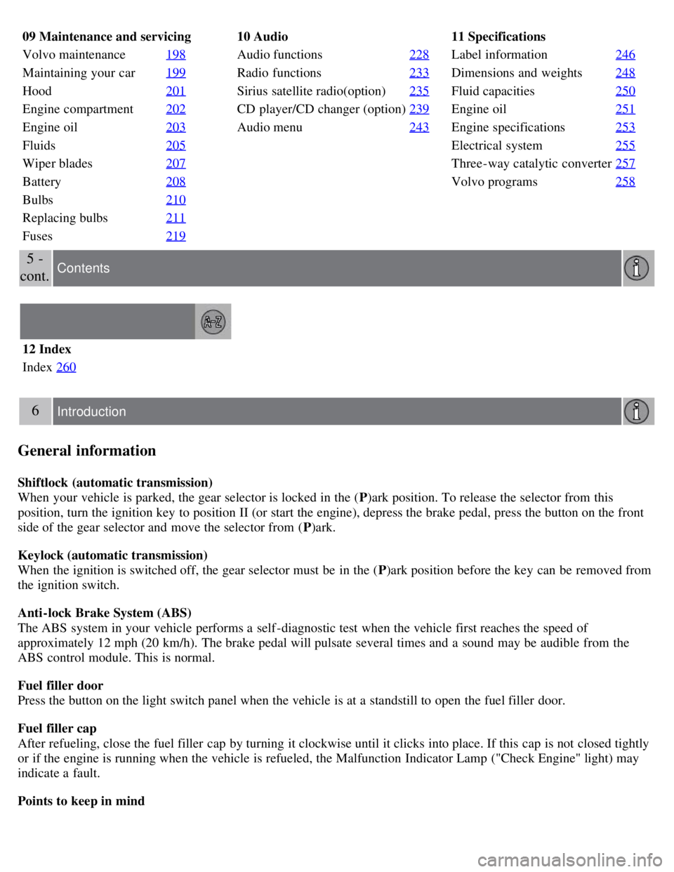
09 Maintenance and servicing
Volvo maintenance198
Maintaining your car199
Hood201
Engine compartment202
Engine oil203
Fluids205
Wiper blades207
Battery208
Bulbs210
Replacing bulbs211
Fuses219
10 Audio
Audio functions 228
Radio functions233
Sirius satellite radio(option)235
CD player/CD changer (option)239
Audio menu243
11 Specifications
Label information246
Dimensions and weights248
Fluid capacities250
Engine oil251
Engine specifications253
Electrical system255
Three-way catalytic converter257
Volvo programs258
5 -
cont. Contents
12 Index
Index 260
6 Introduction
General information
Shiftlock (automatic transmission)
When your vehicle is parked, the gear selector is locked in the ( P)ark position. To release the selector from this
position, turn the ignition key to position II (or start the engine), depress the brake pedal, press the button on the front
side of the gear selector and move the selector from ( P)ark.
Keylock (automatic transmission)
When the ignition is switched off, the gear selector must be in the ( P)ark position before the key can be removed from
the ignition switch.
Anti-lock Brake System (ABS)
The ABS system in your vehicle performs a self -diagnostic test when the vehicle first reaches the speed of
approximately 12 mph (20 km/h). The brake pedal will pulsate several times and a sound may be audible from the
ABS control module. This is normal.
Fuel filler door
Press the button on the light switch panel when the vehicle is at a standstill to open the fuel filler door.
Fuel filler cap
After refueling, close the fuel filler cap by turning it clockwise until it clicks into place. If this cap is not closed tightly
or if the engine is running when the vehicle is refueled, the Malfunction Indicator Lamp ("Check Engine" light) may
indicate a fault.
Points to keep in mind
Page 5 of 234
Before you operate your vehicle for the first time, please familiarize yourself with the new-engine oil consumption
information on page 203. You should also be familiar with the information found in the chapters "Instruments and
controls," and "Starting and driving."
Information contained in the balance of the manual is extremely useful and should be read after operating the
vehicle for the first time.
The manual is structured so that it can be used for reference. For this reason, it should be kept in the vehicle for
ready access.
Do not export your Volvo to another country before investigating that country's applicable safety and emission
control requirements. In some cases it may be difficult or impossible to comply with these requirements. Modifications
to the emission control system(s) may render your Volvo not certifiable for legal operation in the U.S., Canada and
other countries.
All information, illustrations and specifications contained in this manual are based on the latest product information
available at the time of publication. Please note that some vehicles may be equipped differently, depending on special
legal requirements. Optional equipment described in this manual may not be available in all markets.
Volvo reserves the right to make model changes at any time, or to change specifications or design without notice
and without incurring obligation.
WARNING
If your vehicle is involved in an accident, unseen damage may affect its drivability and safety.
7 Introduction
Volvo and the environment
Volvo is committed to the well being of its customers. As a natural part of this commitment, we care about the
environment in which we all live. Caring for the environment means an everyday involvement in reducing our
environmental impact. Volvo's environmental activities are based on a holistic view, which means we consider the
overall environmental impact of a product throughout its complete life cycle. In this context, design, production,
product use, and recycling are all important considerations. In production, Volvo has partly or completely phased out
several chemicals including CFCs, lead chromates, asbestos, and cadmium; and reduced the number of chemicals used
in our plants 50% since 1991.
Volvo was the first in the world to introduce into production a three-way catalytic converter with a Lambda sond, now
called the heated oxygen sensor, in 1976. The current version of this highly efficient system reduces emissions of
harmful substances (CO, HC, NOx) from the exhaust pipe by approximately 95-99% and the search to eliminate the
remaining emissions continues. Volvo is the only automobile manufacturer to offer CFC-free retrofit kits for the air
conditioning system of all models as far back as the 1975 model 240. Advanced electronic engine controls and cleaner
fuels are bringing us closer to our goal. After Volvo vehicles and parts have fulfilled their use, recycling is the next
critical step in completing the life cycle. The metal content is about 75% of the total weight of a vehicle, which makes
the vehicle among the most recycled industrial products. In order to have efficient and well-controlled recycling,
dismantling information is available for all Volvo models. For Volvo, all homogeneous plastic parts weighing more
than 3.4 oz. (100 grams) are marked with international symbols that indicate how the component is to be sorted for
recycling. In addition to continuous environmental refinement of conventional gasoline-powered internal combustion
engines, Volvo is actively looking at advanced technology alternative-fuel vehicles.
When you drive a Volvo, you become our partner in the work to lessen the car's impact on the environment. To reduce
your vehicle's environmental impact, you can:
Maintain proper air pressure in your tires. Tests have shown decreased fuel economy with improperly inflated tires.
Follow the recommended maintenance schedule in your Warranty and Service Records Information booklet.
Drive at a constant speed whenever possible.
Page 26 of 234
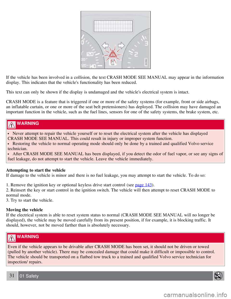
If the vehicle has been involved in a collision, the text CRASH MODE SEE MANUAL may appear in the information
display. This indicates that the vehicle's functionality has been reduced.
This text can only be shown if the display is undamaged and the vehicle's electrical system is intact.
CRASH MODE is a feature that is triggered if one or more of the safety systems (for example, front or side airbags,
an inflatable curtain, or one or more of the seat belt pretensioners) has deployed. The collision may have damaged an
important function in the vehicle, such as the fuel lines, sensors for one of the safety systems, the brake system, etc.
WARNING
Never attempt to repair the vehicle yourself or to reset the electrical system after the vehicle has displayed
CRASH MODE SEE MANUAL. This could result in injury or improper system function.
Restoring the vehicle to normal operating mode should only be done by a trained and qualified Volvo service
technician.
After CRASH MODE SEE MANUAL has been displayed, if you detect the odor of fuel vapor, or see any signs of
fuel leakage, do not attempt to start the vehicle. Leave the vehicle immediately.
Attempting to start the vehicle
If damage to the vehicle is minor and there is no fuel leakage, you may attempt to start the vehicle. To do so:
1. Remove the ignition key or optional keyless drive start control (see page 143
).
2. Reinsert the key or start control in the ignition switch. The vehicle will then attempt to reset CRASH MODE to
normal mode.
3. Try to start the vehicle.
Moving the vehicle
If the electrical system is able to reset system status to normal (CRASH MODE SEE MANUAL will no longer be
displayed), the vehicle may be moved carefully from its present position, if for example, it is blocking traffic. It
should, however, not be moved farther than is absolutely necessary.
WARNING
Even if the vehicle appears to be drivable after CRASH MODE has been set, it should not be driven or towed
(pulled by another vehicle). There may be concealed damage that could make it difficult or impossible to control.
The vehicle should be transported on a flatbed tow truck to a trained and qualified Volvo service technician for
inspection/ repairs.
31 01 Safety
Page 41 of 234
47 02 Instruments and controls
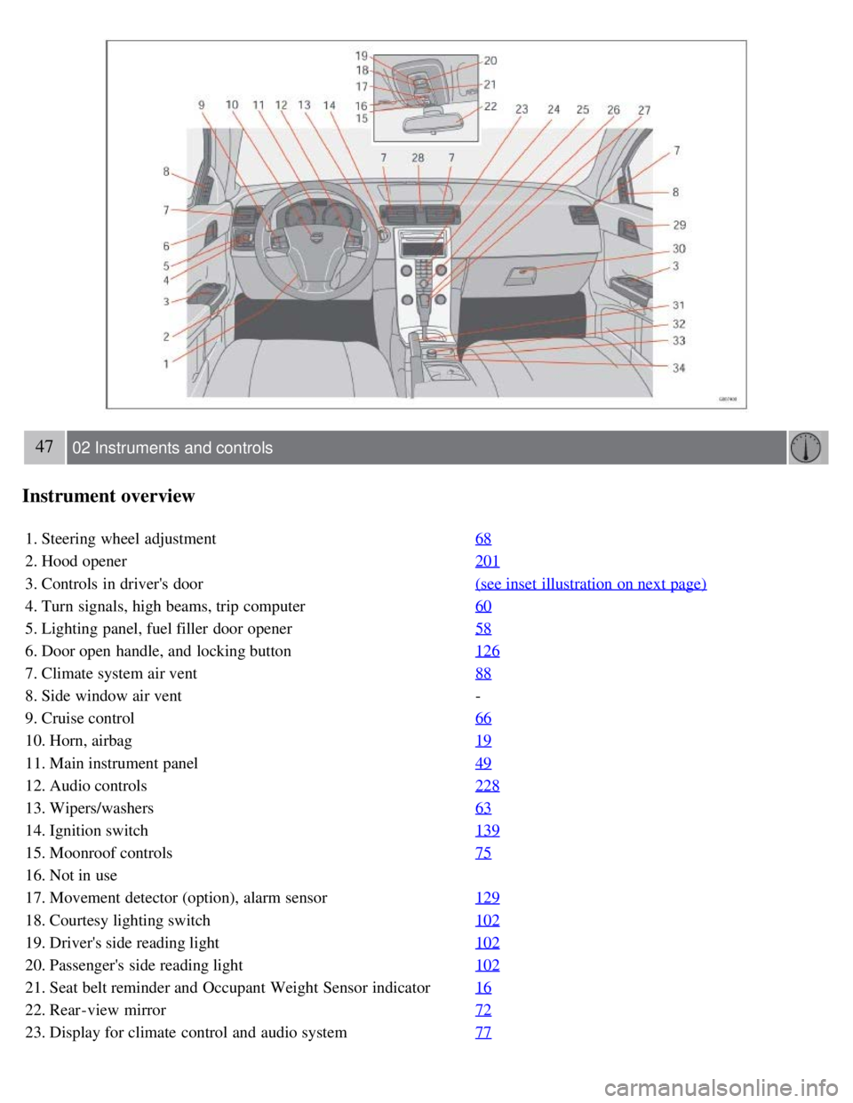
Instrument overview
1. Steering wheel adjustment68
2. Hood opener201
3. Controls in driver's door(see inset illustration on next page)
4. Turn signals, high beams, trip computer60
5. Lighting panel, fuel filler door opener58
6. Door open handle, and locking button126
7. Climate system air vent88
8. Side window air vent-
9. Cruise control 66
10. Horn, airbag19
11. Main instrument panel49
12. Audio controls228
13. Wipers/washers63
14. Ignition switch139
15. Moonroof controls75
16. Not in use
17. Movement detector (option), alarm sensor129
18. Courtesy lighting switch102
19. Driver's side reading light102
20. Passenger's side reading light102
21. Seat belt reminder and Occupant Weight Sensor indicator16
22. Rear-view mirror72
23. Display for climate control and audio system77
Page 43 of 234
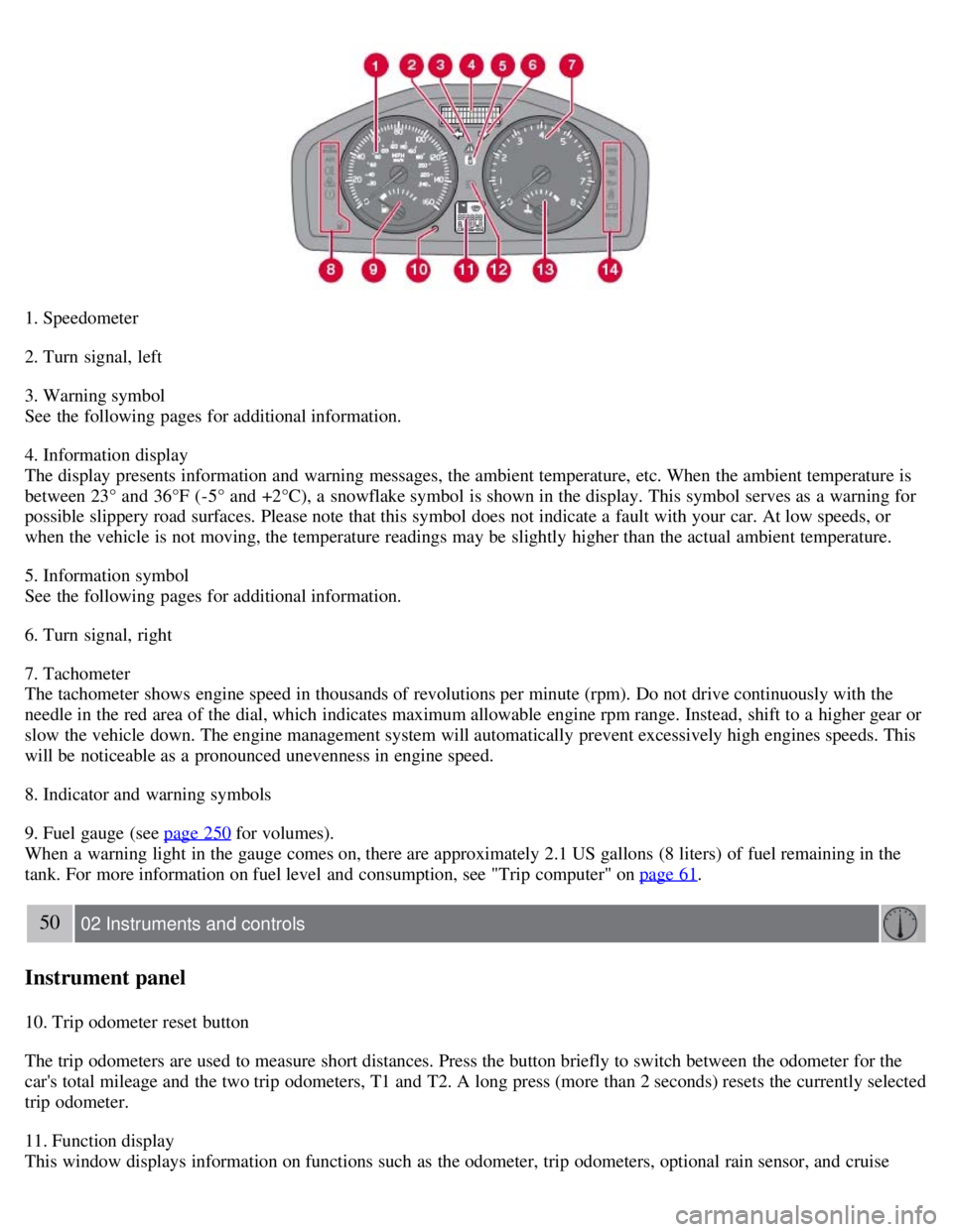
1. Speedometer
2. Turn signal, left
3. Warning symbol
See the following pages for additional information.
4. Information display
The display presents information and warning messages, the ambient temperature, etc. When the ambient temperature is
between 23° and 36°F (-5° and +2°C), a snowflake symbol is shown in the display. This symbol serves as a warning for
possible slippery road surfaces. Please note that this symbol does not indicate a fault with your car. At low speeds, or
when the vehicle is not moving, the temperature readings may be slightly higher than the actual ambient temperature.
5. Information symbol
See the following pages for additional information.
6. Turn signal, right
7. Tachometer
The tachometer shows engine speed in thousands of revolutions per minute (rpm). Do not drive continuously with the
needle in the red area of the dial, which indicates maximum allowable engine rpm range. Instead, shift to a higher gear or
slow the vehicle down. The engine management system will automatically prevent excessively high engines speeds. This
will be noticeable as a pronounced unevenness in engine speed.
8. Indicator and warning symbols
9. Fuel gauge (see page 250
for volumes).
When a warning light in the gauge comes on, there are approximately 2.1 US gallons (8 liters) of fuel remaining in the
tank. For more information on fuel level and consumption, see "Trip computer" on page 61
.
50 02 Instruments and controls
Instrument panel
10. Trip odometer reset button
The trip odometers are used to measure short distances. Press the button briefly to switch between the odometer for the
car's total mileage and the two trip odometers, T1 and T2. A long press (more than 2 seconds) resets the currently selected
trip odometer.
11. Function display
This window displays information on functions such as the odometer, trip odometers, optional rain sensor, and cruise
Page 46 of 234
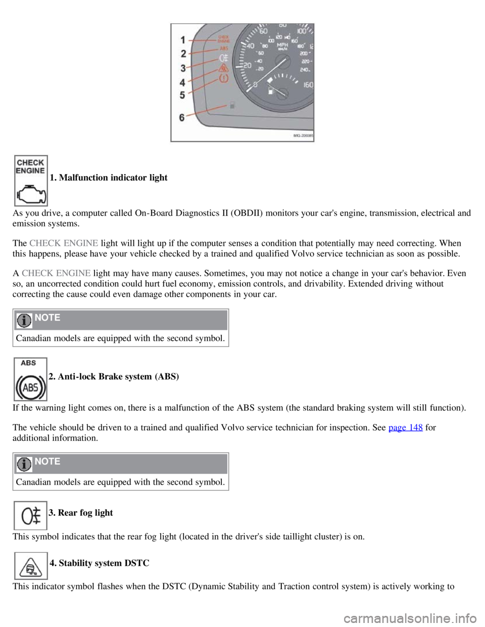
1. Malfunction indicator light
As you drive, a computer called On-Board Diagnostics II (OBDII) monitors your car's engine, transmission, electrical and
emission systems.
The CHECK ENGINE light will light up if the computer senses a condition that potentially may need correcting. When
this happens, please have your vehicle checked by a trained and qualified Volvo service technician as soon as possible.
A CHECK ENGINE light may have many causes. Sometimes, you may not notice a change in your car's behavior. Even
so, an uncorrected condition could hurt fuel economy, emission controls, and drivability. Extended driving without
correcting the cause could even damage other components in your car.
NOTE
Canadian models are equipped with the second symbol.
2. Anti-lock Brake system (ABS)
If the warning light comes on, there is a malfunction of the ABS system (the standard braking system will still function).
The vehicle should be driven to a trained and qualified Volvo service technician for inspection. See page 148
for
additional information.
NOTE
Canadian models are equipped with the second symbol.
3. Rear fog light
This symbol indicates that the rear fog light (located in the driver's side taillight cluster) is on.
4. Stability system DSTC
This indicator symbol flashes when the DSTC (Dynamic Stability and Traction control system) is actively working to
Page 47 of 234
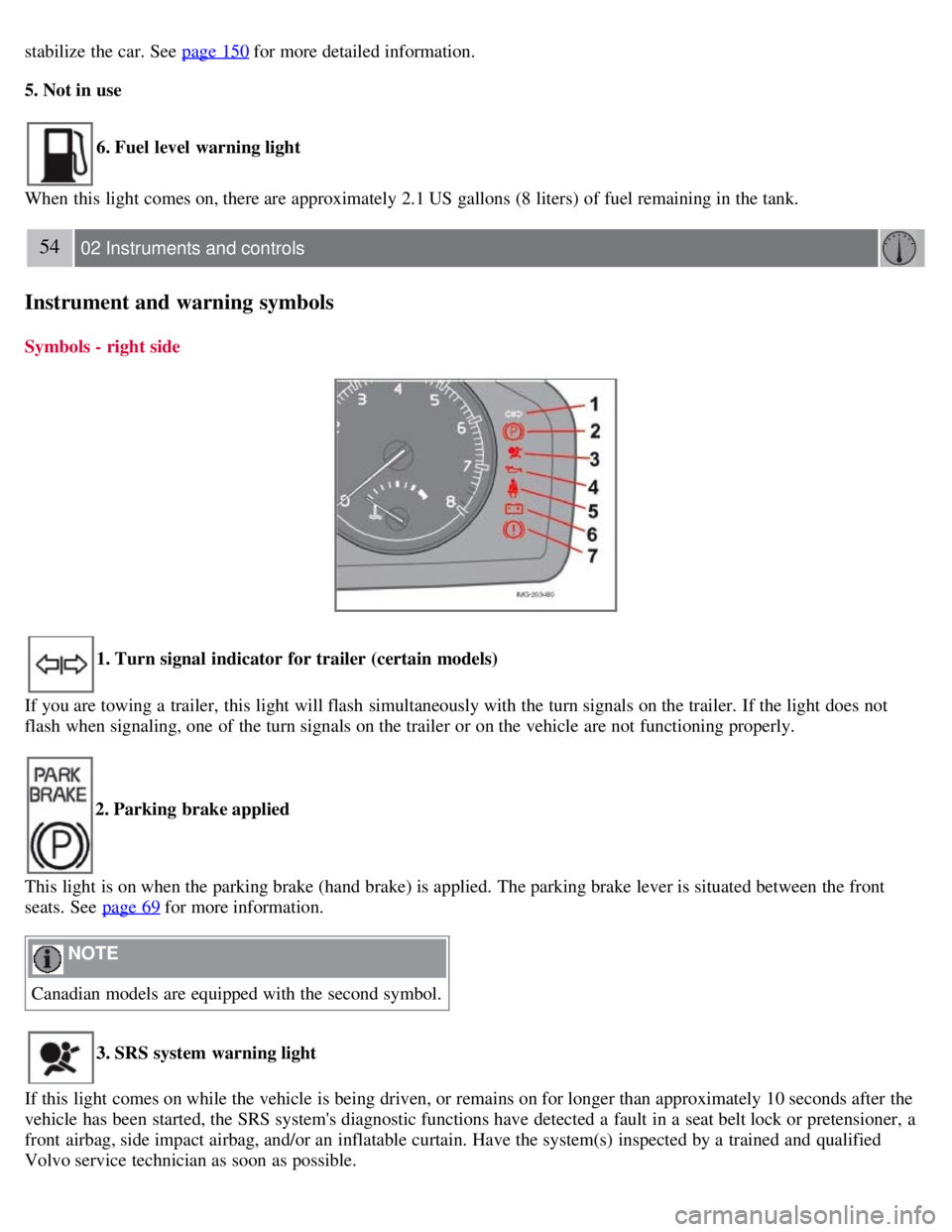
stabilize the car. See page 150 for more detailed information.
5. Not in use
6. Fuel level warning light
When this light comes on, there are approximately 2.1 US gallons (8 liters) of fuel remaining in the tank.
54 02 Instruments and controls
Instrument and warning symbols
Symbols - right side
1. Turn signal indicator for trailer (certain models)
If you are towing a trailer, this light will flash simultaneously with the turn signals on the trailer. If the light does not
flash when signaling, one of the turn signals on the trailer or on the vehicle are not functioning properly.
2. Parking brake applied
This light is on when the parking brake (hand brake) is applied. The parking brake lever is situated between the front
seats. See page 69
for more information.
NOTE
Canadian models are equipped with the second symbol.
3. SRS system warning light
If this light comes on while the vehicle is being driven, or remains on for longer than approximately 10 seconds after the
vehicle has been started, the SRS system's diagnostic functions have detected a fault in a seat belt lock or pretensioner, a
front airbag, side impact airbag, and/or an inflatable curtain. Have the system(s) inspected by a trained and qualified
Volvo service technician as soon as possible.
Page 52 of 234
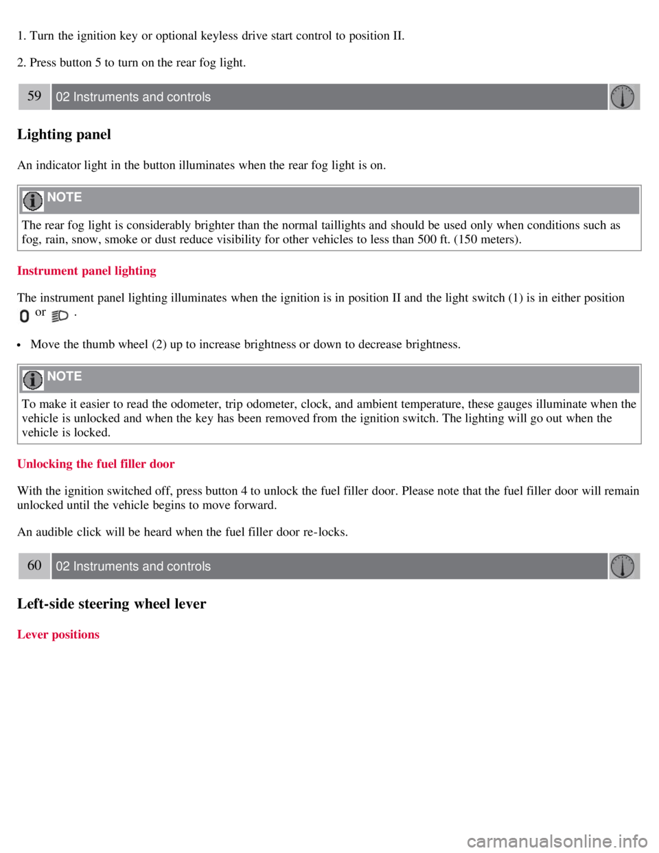
1. Turn the ignition key or optional keyless drive start control to position II.
2. Press button 5 to turn on the rear fog light.
59 02 Instruments and controls
Lighting panel
An indicator light in the button illuminates when the rear fog light is on.
NOTE
The rear fog light is considerably brighter than the normal taillights and should be used only when conditions such as
fog, rain, snow, smoke or dust reduce visibility for other vehicles to less than 500 ft. (150 meters).
Instrument panel lighting
The instrument panel lighting illuminates when the ignition is in position II and the light switch (1) is in either position
or .
Move the thumb wheel (2) up to increase brightness or down to decrease brightness.
NOTE
To make it easier to read the odometer, trip odometer, clock, and ambient temperature, these gauges illuminate when the
vehicle is unlocked and when the key has been removed from the ignition switch. The lighting will go out when the
vehicle is locked.
Unlocking the fuel filler door
With the ignition switched off, press button 4 to unlock the fuel filler door. Please note that the fuel filler door will remain
unlocked until the vehicle begins to move forward.
An audible click will be heard when the fuel filler door re-locks.
60 02 Instruments and controls
Left-side steering wheel lever
Lever positions
Page 54 of 234
of the car.
1. Remove the key from the ignition switch.
2. Pull the direction indicator lever as far as possible towards the steering wheel (to position 4) and release it.
3. Exit the vehicle and lock the doors.
The headlights and parking lights will illuminate and remain on for 30
1, 60 or 90 seconds. The time interval can be
changed according to your preferences by using the Personal Settings function, see page 78
for more information.
1Factory setting
61 02 Instruments and controls
Trip computer (option)
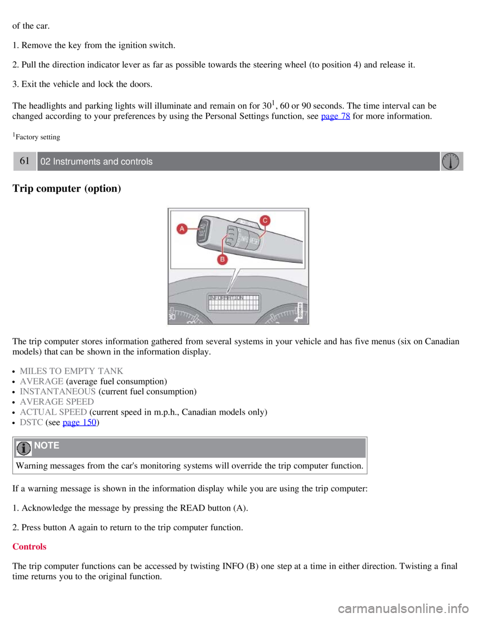
The trip computer stores information gathered from several systems in your vehicle and has five menus (six on Canadian
models) that can be shown in the information display.
MILES TO EMPTY TANK
AVERAGE (average fuel consumption)
INSTANTANEOUS (current fuel consumption)
AVERAGE SPEED
ACTUAL SPEED (current speed in m.p.h., Canadian models only)
DSTC (see page 150)
NOTE
Warning messages from the car's monitoring systems will override the trip computer function.
If a warning message is shown in the information display while you are using the trip computer:
1. Acknowledge the message by pressing the READ button (A).
2. Press button A again to return to the trip computer function.
Controls
The trip computer functions can be accessed by twisting INFO (B) one step at a time in either direction. Twisting a final
time returns you to the original function.