ignition VOLVO C30 2013 Owner´s Manual
[x] Cancel search | Manufacturer: VOLVO, Model Year: 2013, Model line: C30, Model: VOLVO C30 2013Pages: 300, PDF Size: 6.58 MB
Page 6 of 300

Contents
4* Option/accessory, for more information, see Introduction.
06
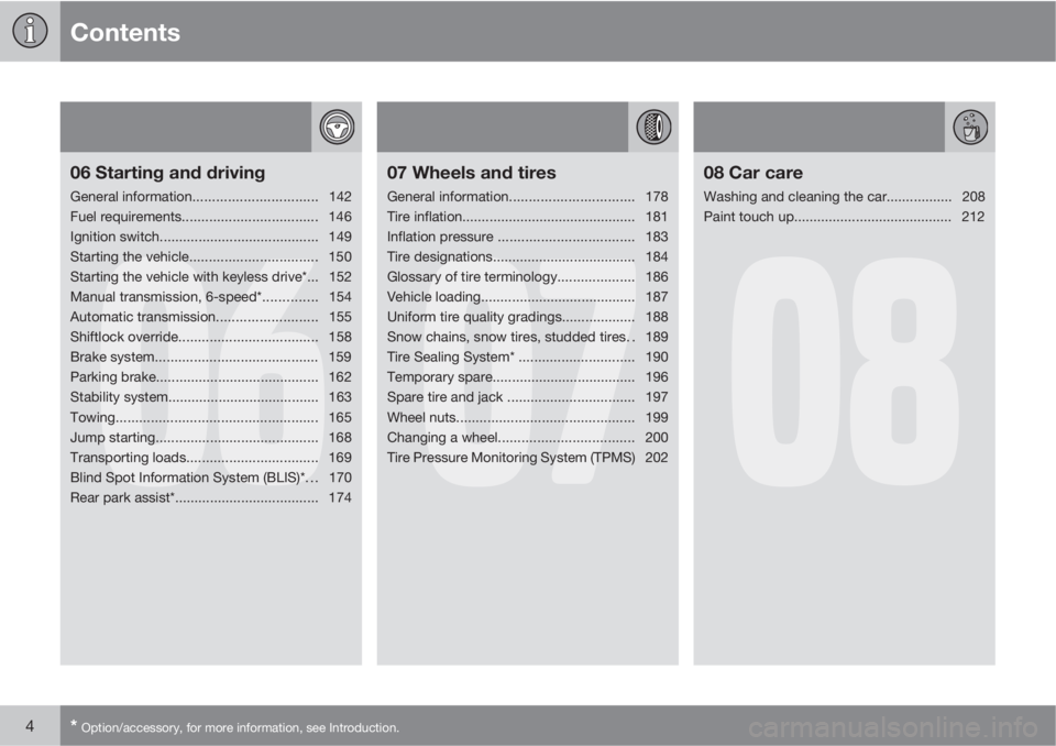
06 Starting and driving
General information................................142
Fuel requirements................................... 146
Ignition switch......................................... 149
Starting the vehicle................................. 150
Starting the vehicle with keyless drive*... 152
Manual transmission, 6-speed*.............. 154
Automatic transmission..........................155
Shiftlock override.................................... 158
Brake system.......................................... 159
Parking brake.......................................... 162
Stability system....................................... 163
Towing.................................................... 165
Jump starting.......................................... 168
Transporting loads.................................. 169
Blind Spot Information System (BLIS)*. . . 170
Rear park assist*..................................... 174
07
07 Wheels and tires
General information................................178
Tire inflation............................................. 181
Inflation pressure ...................................183
Tire designations..................................... 184
Glossary of tire terminology.................... 186
Vehicle loading........................................ 187
Uniform tire quality gradings................... 188
Snow chains, snow tires, studded tires. . 189
Tire Sealing System* .............................. 190
Temporary spare..................................... 196
Spare tire and jack .................................197
Wheel nuts.............................................. 199
Changing a wheel................................... 200
Tire Pressure Monitoring System (TPMS) 202
08
08 Car care
Washing and cleaning the car................. 208
Paint touch up......................................... 212
Page 13 of 300

Introduction
Important information
11
Shiftlock (automatic transmission)When your vehicle is parked, the gear selector
is locked in the P (Park) position. To release the
selector from this position, turn the ignition key
to position II (or start the engine), depress the
brake pedal, press the button on the front side
of the gear selector and move the selector from
P (Park).
Keylock (automatic transmission)When you switch off the ignition, the gear
selector must be in the P (Park) position before
the remote key can be removed from the igni-
tion switch.
Anti-lock Brake System (ABS)The ABS system in your vehicle performs a
self-diagnostic test when the vehicle first rea-
ches the speed of approximately 12 mph
(20 km/h). The brake pedal will pulsate several
times and a sound may be audible from the
ABS control module. This is normal.
Fuel filler doorPress the button on the light switch panel (see
the illustration on page 67) when the vehicle
is at a standstill to unlock the fuel filler door.
Please note that the fuel filler door will remain
unlocked until the vehicle begins to move for-
ward. An audible click will be heard when the
fuel filler door relocks.
Points to keep in mind
•Do not export your Volvo to another coun-
try before investigating that country's
applicable safety and exhaust emission
requirements. In some cases it may be dif-
ficult or impossible to comply with these
requirements. Modifications to the emis-
sion control system(s) may render your
Volvo not certifiable for legal operation in
the U.S., Canada and other countries.
•All information, illustrations and specifica-
tions contained in this manual are based on
the latest product information available at
the time of publication. Please note that
some vehicles may be equipped differ-
ently, depending on special legal require-
ments. Optional equipment described in
this manual may not be available in all mar-
kets.
•Volvo reserves the right to make model
changes at any time, or to change specifi-
cations or design without notice and with-
out incurring obligation.
Volvo Structural Parts Statement
Volvo has always been and continues to be a
leader in automotive safety. Volvo engineers
and manufactures vehicles designed to help
protect vehicle occupants in the event of a col-
lision.
Volvos are designed to absorb the impact of a
collision. This energy absorption system
including, but not limited to, structural compo-
nents such as bumper reinforcement bars,
bumper energy absorbers, frames, rails, fender
aprons, A-pillars, B-pillars and body panels
must work together to maintain cabin integrity
and protect the vehicle occupants.
The supplemental restraint system including
but not limited to air bags, side curtain air bags,
and deployment sensors work together with
the above components to provide proper tim-
ing for air bag deployment.
Due to the above, Volvo Cars of North America
does not support the use of aftermarket, alter-
native or anything other than original Volvo
parts for collision repair.
In addition Volvo does not support the use or
re-use of structural components from an exist-
ing vehicle that has been previously damaged.
Although these parts may appear equivalent, it
is difficult to tell if the parts have been previ-
ously replaced with non-OE parts or if the part
has been damaged as a result of a prior colli-
Page 24 of 300

01 Safety
Seat belts 01
22
steering wheel). Within this context, they
should strive to position the seat with as large
a distance as possible between their belly and
the steering wheel.
Child seats
Please refer to page 40 for information on
securing child seats with the seat belts.
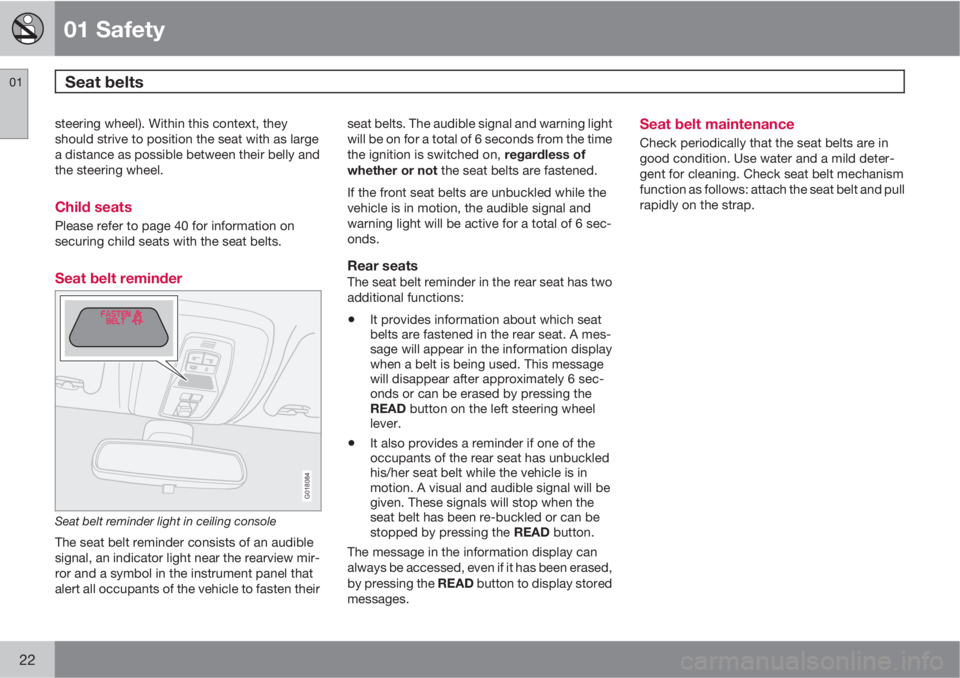
Seat belt reminder
G018084
Seat belt reminder light in ceiling console
The seat belt reminder consists of an audible
signal, an indicator light near the rearview mir-
ror and a symbol in the instrument panel that
alert all occupants of the vehicle to fasten theirseat belts. The audible signal and warning light
will be on for a total of 6 seconds from the time
the ignition is switched on, regardless of
whether or not the seat belts are fastened.
If the front seat belts are unbuckled while the
vehicle is in motion, the audible signal and
warning light will be active for a total of 6 sec-
onds.
Rear seatsThe seat belt reminder in the rear seat has two
additional functions:
•It provides information about which seat
belts are fastened in the rear seat. A mes-
sage will appear in the information display
when a belt is being used. This message
will disappear after approximately 6 sec-
onds or can be erased by pressing the
READ button on the left steering wheel
lever.
•It also provides a reminder if one of the
occupants of the rear seat has unbuckled
his/her seat belt while the vehicle is in
motion. A visual and audible signal will be
given. These signals will stop when the
seat belt has been re-buckled or can be
stopped by pressing the READ button.
The message in the information display can
always be accessed, even if it has been erased,
by pressing the READ button to display stored
messages.
Seat belt maintenance
Check periodically that the seat belts are in
good condition. Use water and a mild deter-
gent for cleaning. Check seat belt mechanism
function as follows: attach the seat belt and pull
rapidly on the strap.
Page 25 of 300

01 Safety
Supplemental Restraint System01
23 Supplemental Restraint System (SRS)
G026330
SRS warning light
As an enhancement to the three-point seat
belts, your Volvo is equipped with a Supple-
mental Restraint System (SRS). Volvo's SRS
consists of seat belt pretensioners, front air-
bags, side impact airbags, the occupant
weight sensor, and inflatable curtains. All of
these systems are monitored by the SRS con-
trol module. An SRS warning light in the instru-
ment panel (see the illustration) illuminates
when the ignition key is turned to position I, II,
or III, and will normally go out after approxi-
mately 7 seconds if no faults are detected in
the system.Where applicable, a text message will also be
displayed when the SRS warning light illumi-
nates. If this warning symbol is not functioning
properly, the general warning symbol illumi-
nates and either
SRS AIRBAG SERVICE
URGENT or SRS AIRBAG SERVICE
REQUIREDwill be displayed.
WARNING
•If the SRS warning light stays on after
the engine has started or if it illuminates
while you are driving, have the vehicle
inspected by a trained and qualified
Volvo service technician as soon as
possible.
•Never try to repair any component or
part of the SRS yourself. Any interfer-
ence in the system could cause mal-
function and serious injury. All work on
these systems should be performed by
a trained and qualified Volvo service
technician.
WARNING
If your vehicle has been subjected to flood
conditions (e.g. soaked carpeting/standing
water on the floor of the vehicle) or if your
vehicle has become flood-damaged in any
way, do not attempt to start the vehicle or
put the key in the ignition before discon-
necting the battery (see below). This may
cause airbag deployment which could result
in personal injury. Have the vehicle towed to
a trained and qualified Volvo service tech-
nician for repairs.
Automatic transmission
Before attempting to tow the vehicle, use
the following procedure to override the
shiftlock system to move the gear selector
to the neutral position:
1. Switch off the ignition for at least
10 minutes and disconnect the battery.
2. Wait at least one minute.
3. Insert the key in the ignition and turn it
to position II.
4. Press firmly on the brake pedal.
5.
Move the gear selector from Park (P) to
the Neutral (N) position, see page 158,
for information on manually overriding
the shiftlock system.
Page 30 of 300

01 Safety
Occupant Weight Sensor (OWS) 01
28
Disabling the passenger's side front
airbag
2
G018082
Occupant Weight Sensor (OWS) indicator light
Volvo recommends that ALL occupants (adults
and children) shorter than 4 feet 7 inches
(140 cm) be seated in the rear seat of any vehi-
cle with a passenger's side front airbag, and be
properly restrained. Children should always be
seated in child restraints appropriate for their
size and weight. See also the child safety rec-
ommendations on page 38.
The Occupant Weight Sensor (OWS) is
designed to meet the regulatory requirements
of Federal Motor Vehicle Safety Standard
(FMVSS) 208 and is designed to disable (willnot inflate) the passenger's side front airbag
under certain conditions.
The OWS works with sensors that are part of
the front passenger's seat and seat belt. The
sensors are designed to detect the presence of
a properly seated occupant and determine if
the passenger's side front airbag should be
enabled (may inflate) or disabled (will not
inflate).
The OWS will disable (will not inflate) the pas-
senger's side front airbag when:
•the front passenger's seat is unoccupied,
or has small/medium objects in the front
seat,
•the system determines that an infant is
present in a rear-facing infant seat that is
installed according to the manufacturer's
instructions,
•the system determines that a small child is
present in a forward-facing child restraint
that is installed according to the manufac-
turer's instructions,
•the system determines that a small child is
present in a booster seat,
•a front passenger takes his/her weight off
of the seat for a period of time,
•a child or a small person occupies the front
passenger's seat.The OWS uses a PASSENGER AIRBAG OFF
indicator lamp which will illuminate and stay on
to remind you that the passenger's side front
airbag is disabled. The PASSENGER AIRBAG
OFF indicator lamp is located in the overhead
console, near the base of the rearview mirror.
NOTE
When the ignition is switched on, the OWS
indicator light will go on for up to 10 seconds
while the system performs a self-diagnostic
test.
However, if a fault is detected in the system:
•The OWS indicator light will stay on
•The SRS warning light (see page 23) will
come on and stay on
The message
PASS. AIRBAG OFF SERVICE
URGENT will be displayed in the information
display.
Page 39 of 300

01 Safety
Crash mode01
37 Driving after a collision
G026363
If the vehicle has been involved in a collision,
the text CRASH MODE SEE MANUAL may
appear in the information display. This indi-
cates that the vehicle's functionality has been
reduced.
This text can only be shown if the display is
undamaged and the vehicle's electrical system
is intact.
CRASH MODE is a feature that is triggered if
one or more of the safety systems (for example,
front or side airbags, an inflatable curtain, or
one or more of the seat belt pretensioners) has
deployed. The collision may have damaged an
important function in the vehicle, such as thefuel lines, sensors for one of the safety sys-
tems, the brake system, etc.
WARNING
•Never attempt to repair the vehicle
yourself or to reset the electrical system
after the vehicle has displayed
CRASH
MODE SEE MANUAL. This could
result in injury or improper system func-
tion.
•Restoring the vehicle to normal operat-
ing mode should only be done by a
trained and qualified Volvo service tech-
nician.
•After CRASH MODE SEE MANUALhas been displayed, if you detect the
odor of fuel vapor, or see any signs of
fuel leakage, do not attempt to start the
vehicle. Leave the vehicle immediately.
Attempting to start the vehicleIf damage to the vehicle is minor and there is
no fuel leakage, you may attempt to start the
vehicle. To do so:
1. Remove the ignition key or optional keyless
drive start control, see page 152.
2. Reinsert the key or start control in the igni-
tion switch. The vehicle will then attempt to
reset CRASH MODE to normal mode.3. Try to start the vehicle.
Moving the vehicleIf the electrical system is able to reset system
status to normal (CRASH MODE SEE
MANUAL will no longer be displayed), the
vehicle may be moved carefully from its pres-
ent position, if for example, it is blocking traffic.
It should, however, not be moved farther than
is absolutely necessary.
WARNING
Even if the vehicle appears to be drivable
after CRASH MODE has been set, it should
not be driven or towed (pulled by another
vehicle). There may be concealed damage
that could make it difficult or impossible to
control. The vehicle should be transported
on a flatbed tow truck to a trained and quali-
fied Volvo service technician for inspection/
repairs.
Page 55 of 300

02 Instruments and controls
Instrument overview
02
* Option/accessory, for more information, see Introduction.53
Steering wheel adjustment
Hood opener
Controls in front doors
Left steering wheel lever
Lighting panel, fuel filler door opener
Door open handle and locking button
Climate system air vent
Side window air vent
Cruise control
Horn, airbag
Main instrument panel
Audio controls
Right steering wheel lever
Ignition switch
Moonroof control*
Not in use
Not is use
Courtesy lighting switch
Driver's side reading light
Passenger's side reading light
Seat belt reminder and Occupant
Weight Sensor indicator
Rear-view mirror
Display for climate control, personal
settings, and audio system
Audio system
Controls for personal settings and
audio system
Controls for climate system
Gear selector
Hazard warning flashers
Door open handle
Glove compartment
Parking brake
12-volt socket
Position for optional equipment
Position for optional equipment
Control panel in driver's door
Power windows
Door mirror button, driver's side
Door mirror adjustment control
Door mirror button, passenger's side
Page 58 of 300

02 Instruments and controls
Indicator and warning symbols
02
56
Function check
The indicator and warning symbols1 light up
when you turn the ignition key or the optional
keyless drive start control to the driving posi-
tion (position II) before starting. This shows that
the symbols are functioning.
When the engine starts, all sym-
bols go out. If the engine is not
started within 5 seconds, all of the
symbols except the malfunction
indicator light (CHECK ENGINE)
and the oil pressure warning light
will go out. Certain symbols may
not have their functions illustrated, depending
on the car's equipment.
The PARK BRAKE symbol will not go out until
the parking brake has been released.
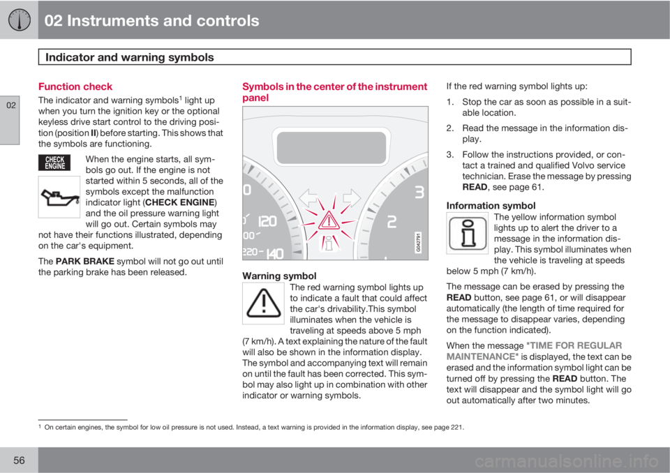
Symbols in the center of the instrument
panel
Warning symbolThe red warning symbol lights up
to indicate a fault that could affect
the car's drivability.This symbol
illuminates when the vehicle is
traveling at speeds above 5 mph
(7 km/h). A text explaining the nature of the fault
will also be shown in the information display.
The symbol and accompanying text will remain
on until the fault has been corrected. This sym-
bol may also light up in combination with other
indicator or warning symbols.
If the red warning symbol lights up:
1. Stop the car as soon as possible in a suit-
able location.
2. Read the message in the information dis-
play.
3. Follow the instructions provided, or con-
tact a trained and qualified Volvo service
technician. Erase the message by pressing
READ, see page 61.
Information symbolThe yellow information symbol
lights up to alert the driver to a
message in the information dis-
play. This symbol illuminates when
the vehicle is traveling at speeds
below 5 mph (7 km/h).
The message can be erased by pressing the
READ button, see page 61, or will disappear
automatically (the length of time required for
the message to disappear varies, depending
on the function indicated).
When the message "
TIME FOR REGULAR
MAINTENANCE" is displayed, the text can be
erased and the information symbol light can be
turned off by pressing the READ button. The
text will disappear and the symbol light will go
out automatically after two minutes.
1On certain engines, the symbol for low oil pressure is not used. Instead, a text warning is provided in the information display, see page 221.
Page 66 of 300

02 Instruments and controls
Lighting panel
02
64* Option/accessory, for more information, see Introduction.
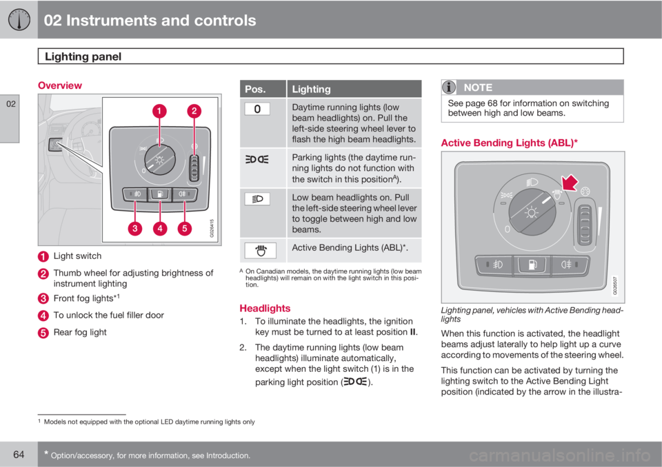
Overview
G026415
Light switch
Thumb wheel for adjusting brightness of
instrument lighting
Front fog lights*1
To unlock the fuel filler door
Rear fog light
Pos.Lighting
Daytime running lights (low
beam headlights) on. Pull the
left-side steering wheel lever to
flash the high beam headlights.
Parking lights (the daytime run-
ning lights do not function with
the switch in this position
A).
Low beam headlights on. Pull
the left-side steering wheel lever
to toggle between high and low
beams.
Active Bending Lights (ABL)*.
AOn Canadian models, the daytime running lights (low beam
headlights) will remain on with the light switch in this posi-
tion.
Headlights
1. To illuminate the headlights, the ignition
key must be turned to at least position II.
2. The daytime running lights (low beam
headlights) illuminate automatically,
except when the light switch (1) is in the
parking light position (
).
NOTE
See page 68 for information on switching
between high and low beams.
Active Bending Lights (ABL)*
G026507
Lighting panel, vehicles with Active Bending head-
lights
When this function is activated, the headlight
beams adjust laterally to help light up a curve
according to movements of the steering wheel.
This function can be activated by turning the
lighting switch to the Active Bending Light
position (indicated by the arrow in the illustra-
1Models not equipped with the optional LED daytime running lights only
Page 68 of 300

02 Instruments and controls
Lighting panel
02
66* Option/accessory, for more information, see Introduction.
tions. A light sensor then monitors the ambient
lighting conditions and automatically switches
from LED DRL to the low beam headlights in
weaker ambient light (and will switch back to
DRL when the ambient light becomes brighter).
The LED DRLs will also switch off automatically
(and the low beams will switch on) if:
•The rear fog light is switched on
•The windshield wipers are switched on for
more than 10 seconds
WARNING
•DRL is a driving aid designed to help
conserve electrical current. This system
cannot always determine if the ambient
lighting conditions are sufficient for
switching from low beams to DRL (or
vice versa). It is always the driver's
responsibility to visually determine if the
low beam headlights should be used.
•As the driver, you have full responsibility
for operating the vehicle in a safe man-
ner.
Parking lights
The front and rear parking lights can be turned
on even when the ignition is switched off.
–Turn the light switch (1) to the parking light
position.
The license plate lights also illuminate when the
parking lights are switched on.
Brake lights
The brake lights come on automatically when
the brakes are applied.
Fog lights
Front fog lights*2
The front fog lights can be used in combination
with either the headlights or the parking lights.
1.
Turn the ignition key to position II.
2. Press button (3) to turn on the front fog
lights.
An indicator light in the button illuminates when
the front fog lights are on.
Rear fog lightsThe rear fog lights are located in both taillight
clusters.The rear fogs light will only function in combi-
nation with the high/low beam headlights or the
optional front fog lights.
1.
Turn the ignition key to position II.
2. Press button (5) to turn on the rear fog
lights.
An indicator light in the button illuminates when
the rear fog lights are on.
NOTE
The rear fog lights are considerably brighter
than the normal taillights and should be
used only when conditions such as fog, rain,
snow, smoke or dust reduce visibility for
other vehicles to less than 500 ft.
(150 meters).
Instrument panel lighting
The instrument panel lighting illuminates when
the ignition is in position II and the light
switch (1) is in either position
or .
2Not available on models equipped with the optional LED Daytime Running LIGHTS