VOLVO C30 2013 Owner´s Manual
Manufacturer: VOLVO, Model Year: 2013, Model line: C30, Model: VOLVO C30 2013Pages: 300, PDF Size: 6.58 MB
Page 61 of 300
02 Instruments and controls
Symbols – instrument panel
02
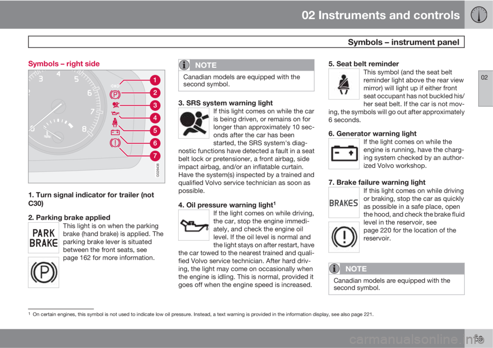
59 Symbols – right side
G026438
1. Turn signal indicator for trailer (not
C30)
2. Parking brake applied
This light is on when the parking
brake (hand brake) is applied. The
parking brake lever is situated
between the front seats, see
page 162 for more information.
NOTE
Canadian models are equipped with the
second symbol.
3. SRS system warning lightIf this light comes on while the car
is being driven, or remains on for
longer than approximately 10 sec-
onds after the car has been
started, the SRS system's diag-
nostic functions have detected a fault in a seat
belt lock or pretensioner, a front airbag, side
impact airbag, and/or an inflatable curtain.
Have the system(s) inspected by a trained and
qualified Volvo service technician as soon as
possible.
4. Oil pressure warning light1
If the light comes on while driving,
the car, stop the engine immedi-
ately, and check the engine oil
level. If the oil level is normal and
the light stays on after restart, have
the car towed to the nearest trained and quali-
fied Volvo service technician. After hard driv-
ing, the light may come on occasionally when
the engine is idling. This is normal, provided it
goes off when the engine speed is increased.
5. Seat belt reminderThis symbol (and the seat belt
reminder light above the rear view
mirror) will light up if either front
seat occupant has not buckled his/
her seat belt. If the car is not mov-
ing, the symbols will go out after approximately
6 seconds.
6. Generator warning lightIf the light comes on while the
engine is running, have the charg-
ing system checked by an author-
ized Volvo workshop.
7. Brake failure warning lightIf this light comes on while driving
or braking, stop the car as quickly
as possible in a safe place, open
the hood, and check the brake fluid
level in the reservoir, see
page 220 for the location of the
reservoir.
NOTE
Canadian models are equipped with the
second symbol.
1On certain engines, this symbol is not used to indicate low oil pressure. Instead, a text warning is provided in the information display, see also page 221.
Page 62 of 300
02 Instruments and controls
Symbols – instrument panel
02
60
WARNING
If the fluid level is below the MIN mark in the
reservoir or if a BRAKE FAILURE STOP
SAFELY message is displayed in the infor-
mation display: DO NOT DRIVE. Have the
car towed to a trained and qualified Volvo
service technician and have the brake sys-
tem inspected.
If the BRAKES and ABS warning lights come
on at the same time, this could indicate a fault
in the brake system.
In this case:
1. Stop the car in a suitable place and switch
off the engine.
2. Restart the engine.
3. If both warning lights go off, no further
action is required and the car can be
driven.
4. If both lights remain on after the engine has
been restarted, switch off the engine again
and check the brake fluid level, see
page 220 for the location of the reservoir.
Door open warning
The driver will be alerted if one of the doors, the
hood or the liftgate are open or ajar.
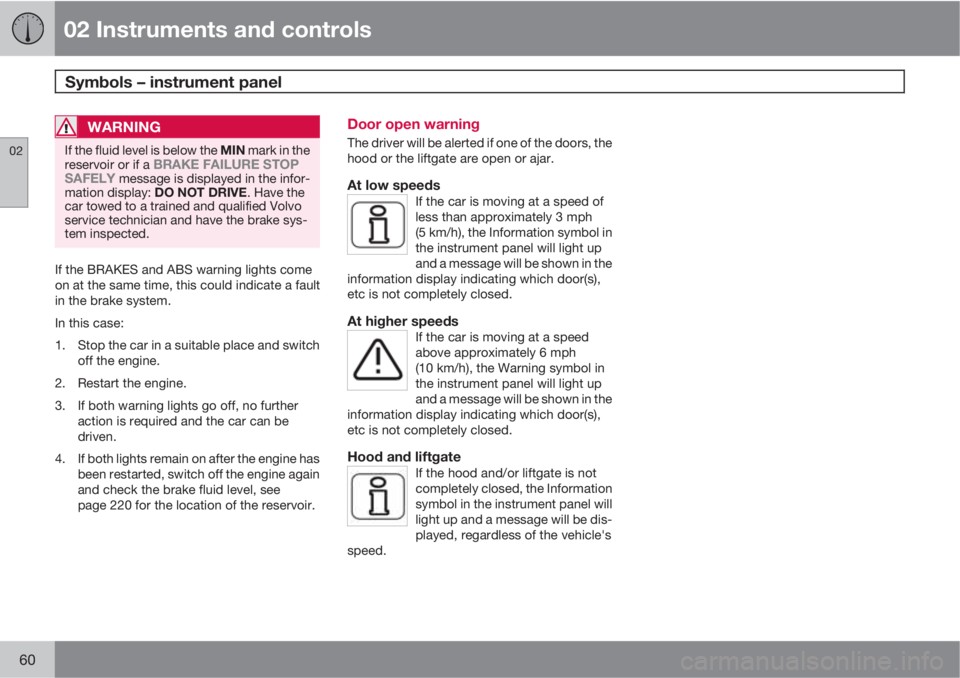
At low speedsIf the car is moving at a speed of
less than approximately 3 mph
(5 km/h), the Information symbol in
the instrument panel will light up
and a message will be shown in the
information display indicating which door(s),
etc is not completely closed.
At higher speedsIf the car is moving at a speed
above approximately 6 mph
(10 km/h), the Warning symbol in
the instrument panel will light up
and a message will be shown in the
information display indicating which door(s),
etc is not completely closed.
Hood and liftgateIf the hood and/or liftgate is not
completely closed, the Information
symbol in the instrument panel will
light up and a message will be dis-
played, regardless of the vehicle's
speed.
Page 63 of 300
02 Instruments and controls
Information display
02
61 Messages
G019617
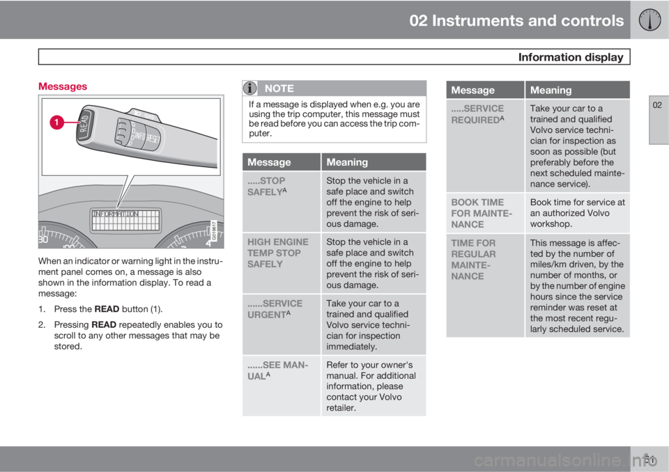
When an indicator or warning light in the instru-
ment panel comes on, a message is also
shown in the information display. To read a
message:
1.
Press the READ button (1).
2.
Pressing READ repeatedly enables you to
scroll to any other messages that may be
stored.
NOTE
If a message is displayed when e.g. you are
using the trip computer, this message must
be read before you can access the trip com-
puter.
MessageMeaning
.....STOP
SAFELYAStop the vehicle in a
safe place and switch
off the engine to help
prevent the risk of seri-
ous damage.
HIGH ENGINE
TEMP STOP
SAFELYStop the vehicle in a
safe place and switch
off the engine to help
prevent the risk of seri-
ous damage.
......SERVICE
URGENTATake your car to a
trained and qualified
Volvo service techni-
cian for inspection
immediately.
......SEE MAN-
UALARefer to your owner's
manual. For additional
information, please
contact your Volvo
retailer.
MessageMeaning
.....SERVICE
REQUIREDATake your car to a
trained and qualified
Volvo service techni-
cian for inspection as
soon as possible (but
preferably before the
next scheduled mainte-
nance service).
BOOK TIME
FOR MAINTE-
NANCEBook time for service at
an authorized Volvo
workshop.
TIME FOR
REGULAR
MAINTE-
NANCEThis message is affec-
ted by the number of
miles/km driven, by the
number of months, or
by the number of engine
hours since the service
reminder was reset at
the most recent regu-
larly scheduled service.
Page 64 of 300
02 Instruments and controls
Information display
02
62
MessageMeaning
MAINTE-
NANCE OVER-
DUEIf the vehicle is not serv-
iced according to
schedule, the warranty
may not apply to dam-
aged parts, etc.
REMINDER
CHECK OIL
LEVELStop as soon as possi-
ble and switch off the
engine, check the oil
level and top up if nec-
essary, see page 221.
AThis is part of the message. Additional information will also
be displayed.
Page 65 of 300
02 Instruments and controls
12-volt sockets
02
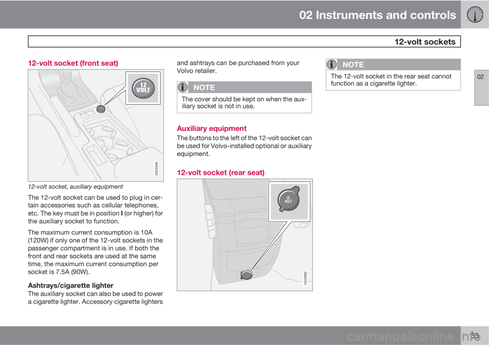
63 12-volt socket (front seat)
G026349
12-volt socket, auxiliary equipment
The 12-volt socket can be used to plug in cer-
tain accessories such as cellular telephones,
etc. The key must be in position I (or higher) for
the auxiliary socket to function.
The maximum current consumption is 10A
(120W) if only one of the 12-volt sockets in the
passenger compartment is in use. If both the
front and rear sockets are used at the same
time, the maximum current consumption per
socket is 7.5A (90W).
Ashtrays/cigarette lighterThe auxiliary socket can also be used to power
a cigarette lighter. Accessory cigarette lightersand ashtrays can be purchased from your
Volvo retailer.
NOTE
The cover should be kept on when the aux-
iliary socket is not in use.
Auxiliary equipment
The buttons to the left of the 12-volt socket can
be used for Volvo-installed optional or auxiliary
equipment.
12-volt socket (rear seat)
G029082
NOTE
The 12-volt socket in the rear seat cannot
function as a cigarette lighter.
Page 66 of 300
02 Instruments and controls
Lighting panel
02
64* Option/accessory, for more information, see Introduction.
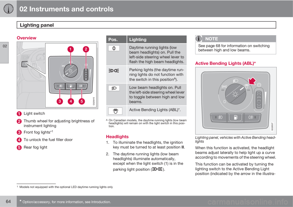
Overview
G026415
Light switch
Thumb wheel for adjusting brightness of
instrument lighting
Front fog lights*1
To unlock the fuel filler door
Rear fog light
Pos.Lighting
Daytime running lights (low
beam headlights) on. Pull the
left-side steering wheel lever to
flash the high beam headlights.
Parking lights (the daytime run-
ning lights do not function with
the switch in this position
A).
Low beam headlights on. Pull
the left-side steering wheel lever
to toggle between high and low
beams.
Active Bending Lights (ABL)*.
AOn Canadian models, the daytime running lights (low beam
headlights) will remain on with the light switch in this posi-
tion.
Headlights
1. To illuminate the headlights, the ignition
key must be turned to at least position II.
2. The daytime running lights (low beam
headlights) illuminate automatically,
except when the light switch (1) is in the
parking light position (
).
NOTE
See page 68 for information on switching
between high and low beams.
Active Bending Lights (ABL)*
G026507
Lighting panel, vehicles with Active Bending head-
lights
When this function is activated, the headlight
beams adjust laterally to help light up a curve
according to movements of the steering wheel.
This function can be activated by turning the
lighting switch to the Active Bending Light
position (indicated by the arrow in the illustra-
1Models not equipped with the optional LED daytime running lights only
Page 67 of 300
02 Instruments and controls
Lighting panel
02
* Option/accessory, for more information, see Introduction.65
tion). The indicator light in the Active
Bending Light symbol will illuminate. The func-
tion can be deactivated by turning the lighting
switch counterclockwise to one of the other
lighting positions.
G020789
Headlight pattern with ABL deactivated (left) and
activated (right)
NOTE
•This function can only be activated in
twilight or dark conditions, and only
when the vehicle is in motion.
•If the indicator light flashes, this indi-
cates a fault in the ABL system. A text
message will also be displayed.
LED Daytime Running Lights (DRL)*
To help conserve fuel by reducing the use of
electrical current in the vehicle, DRL can be
used in daylight conditions instead of the low
beam headlights, which consume more elec-
trical current. The daytime running lights are
mounted in the front spoiler and use bright,
electricity-saving LEDs (light emitting diodes).
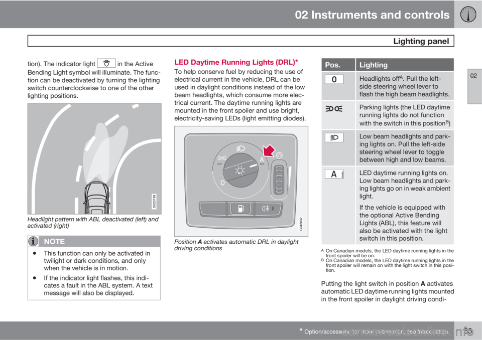
Position A activates automatic DRL in daylight
driving conditions
Pos.Lighting
Headlights offA. Pull the left-
side steering wheel lever to
flash the high beam headlights.
Parking lights (the LED daytime
running lights do not function
with the switch in this position
B)
Low beam headlights and park-
ing lights on. Pull the left-side
steering wheel lever to toggle
between high and low beams.
LED daytime running lights on.
Low beam headlights and park-
ing lights go on in weak ambient
light.
If the vehicle is equipped with
the optional Active Bending
Lights (ABL), this feature will
also be activated with the light
switch in this position.
AOn Canadian models, the LED daytime running lights in the
front spoiler will be on.
BOn Canadian models, the LED daytime running lights in the
front spoiler will remain on with the light switch in this posi-
tion.
Putting the light switch in position A activates
automatic LED daytime running lights mounted
in the front spoiler in daylight driving condi-
Page 68 of 300

02 Instruments and controls
Lighting panel
02
66* Option/accessory, for more information, see Introduction.
tions. A light sensor then monitors the ambient
lighting conditions and automatically switches
from LED DRL to the low beam headlights in
weaker ambient light (and will switch back to
DRL when the ambient light becomes brighter).
The LED DRLs will also switch off automatically
(and the low beams will switch on) if:
•The rear fog light is switched on
•The windshield wipers are switched on for
more than 10 seconds
WARNING
•DRL is a driving aid designed to help
conserve electrical current. This system
cannot always determine if the ambient
lighting conditions are sufficient for
switching from low beams to DRL (or
vice versa). It is always the driver's
responsibility to visually determine if the
low beam headlights should be used.
•As the driver, you have full responsibility
for operating the vehicle in a safe man-
ner.
Parking lights
The front and rear parking lights can be turned
on even when the ignition is switched off.
–Turn the light switch (1) to the parking light
position.
The license plate lights also illuminate when the
parking lights are switched on.
Brake lights
The brake lights come on automatically when
the brakes are applied.
Fog lights
Front fog lights*2
The front fog lights can be used in combination
with either the headlights or the parking lights.
1.
Turn the ignition key to position II.
2. Press button (3) to turn on the front fog
lights.
An indicator light in the button illuminates when
the front fog lights are on.
Rear fog lightsThe rear fog lights are located in both taillight
clusters.The rear fogs light will only function in combi-
nation with the high/low beam headlights or the
optional front fog lights.
1.
Turn the ignition key to position II.
2. Press button (5) to turn on the rear fog
lights.
An indicator light in the button illuminates when
the rear fog lights are on.
NOTE
The rear fog lights are considerably brighter
than the normal taillights and should be
used only when conditions such as fog, rain,
snow, smoke or dust reduce visibility for
other vehicles to less than 500 ft.
(150 meters).
Instrument panel lighting
The instrument panel lighting illuminates when
the ignition is in position II and the light
switch (1) is in either position
or .
2Not available on models equipped with the optional LED Daytime Running LIGHTS
Page 69 of 300
02 Instruments and controls
Lighting panel
02
67
NOTE
To make it easier to read the odometer, trip
odometer, clock, and ambient temperature,
these gauges illuminate when the vehicle is
unlocked and when the key has been
removed from the ignition switch. The light-
ing will go out when the vehicle is locked.
Move the thumb wheel (2) up to increase
brightness or down to decrease brightness.
Unlocking the fuel filler door
With the ignition switched off, press button (4)
to unlock the fuel filler door. Please note that
the fuel filler door will remain unlocked until the
car begins to move forward.
An audible click will be heard when the fuel filler
door re-locks.
Page 70 of 300
02 Instruments and controls
Left-side steering wheel lever
02
68* Option/accessory, for more information, see Introduction.
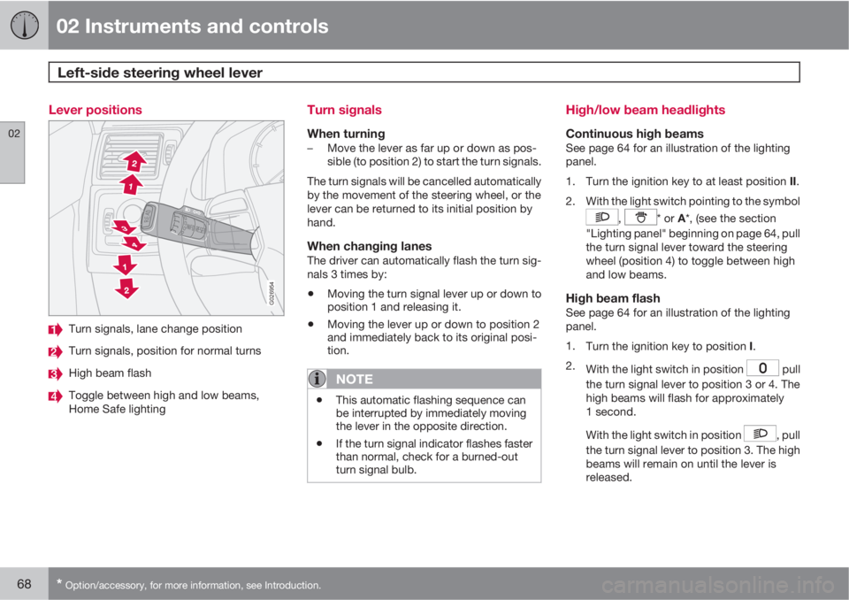
Lever positions
G026954
Turn signals, lane change position
Turn signals, position for normal turns
High beam flash
Toggle between high and low beams,
Home Safe lighting
Turn signals
When turning–Move the lever as far up or down as pos-
sible (to position 2) to start the turn signals.
The turn signals will be cancelled automatically
by the movement of the steering wheel, or the
lever can be returned to its initial position by
hand.
When changing lanesThe driver can automatically flash the turn sig-
nals 3 times by:
•Moving the turn signal lever up or down to
position 1 and releasing it.
•Moving the lever up or down to position 2
and immediately back to its original posi-
tion.
NOTE
•This automatic flashing sequence can
be interrupted by immediately moving
the lever in the opposite direction.
•If the turn signal indicator flashes faster
than normal, check for a burned-out
turn signal bulb.
High/low beam headlights
Continuous high beamsSee page 64 for an illustration of the lighting
panel.
1.
Turn the ignition key to at least position II.
2. With the light switch pointing to the symbol
, * or A*, (see the section
"Lighting panel" beginning on page 64, pull
the turn signal lever toward the steering
wheel (position 4) to toggle between high
and low beams.
High beam flashSee page 64 for an illustration of the lighting
panel.
1.
Turn the ignition key to position I.
2.
With the light switch in position
pull
the turn signal lever to position 3 or 4. The
high beams will flash for approximately
1 second.
With the light switch in position
, pull
the turn signal lever to position 3. The high
beams will remain on until the lever is
released.