steering VOLVO C70 2003 Owners Manual
[x] Cancel search | Manufacturer: VOLVO, Model Year: 2003, Model line: C70, Model: VOLVO C70 2003Pages: 98, PDF Size: 1.64 MB
Page 8 of 98
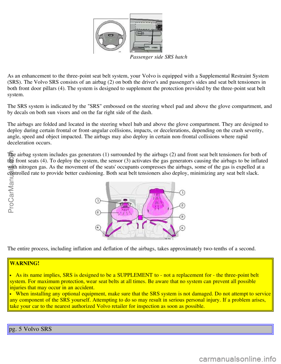
Passenger side SRS hatch
As an enhancement to the three-point seat belt system, your Volvo is equipped with a Supplemental Restraint System
(SRS). The Volvo SRS consists of an airbag (2) on both the driver's and passenger's sides and seat belt tensioners in
both front door pillars (4). The system is designed to supplement the protection provided by the three-point seat belt
system.
The SRS system is indicated by the "SRS" embossed on the steering wheel pad and above the glove compartment, and
by decals on both sun visors and on the far right side of the dash.
The airbags are folded and located in the steering wheel hub and above the glove compartment. They are designed to
deploy during certain frontal or front -angular collisions, impacts, or decelerations, depending on the crash severity,
angle, speed and object impacted. The airbags may also deploy in certain non-frontal collisions where rapid
deceleration occurs.
The airbag system includes gas generators (1) surrounded by the airbags (2) and front seat belt tensioners for both of
the front seats (4). To deploy the system, the sensor (3) activates the gas generators causing the airbags to be inflated
with nitrogen gas. As the movement of the seats' occupants compresses the airbags, some of the gas is expelled at a
controlled rate to provide better cushioning. Both seat belt tensioners also deploy, minimizing any seat belt slack.
The entire process, including inflation and deflation of the airbags, takes approximately two-tenths of a second. WARNING!
As its name implies, SRS is designed to be a SUPPLEMENT to - not a replacement for - the three-point belt
system. For maximum protection, wear seat belts at all times. Be aware that no system can prevent all possible
injuries that may occur in an accident.
When installing any optional equipment, make sure that the SRS system is not damaged. Do not attempt to service
any component of the SRS yourself. Attempting to do so may result in serious personal injury. If a problem arises,
take your car to the nearest authorized Volvo retailer for inspection as soon as possible.
pg. 5 Volvo SRS
ProCarManuals.com
Page 9 of 98
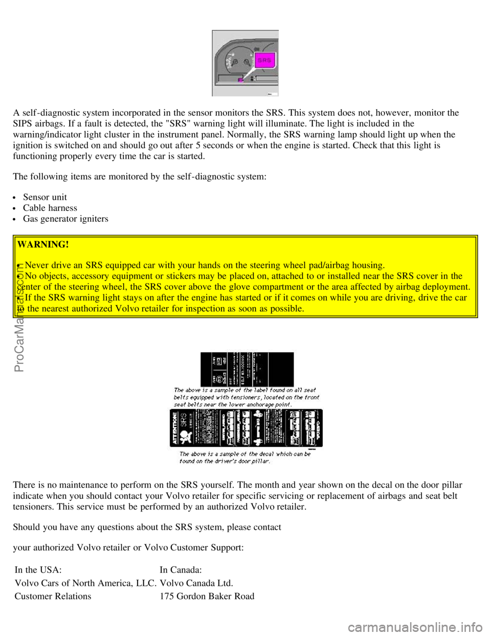
A self -diagnostic system incorporated in the sensor monitors the SRS. This system does not, however, monitor the
SIPS airbags. If a fault is detected, the "SRS" warning light will illuminate. The light is included in the
warning/indicator light cluster in the instrument panel. Normally, the SRS warning lamp should light up when the
ignition is switched on and should go out after 5 seconds or when the engine is started. Check that this light is
functioning properly every time the car is started.
The following items are monitored by the self -diagnostic system:
Sensor unit
Cable harness
Gas generator igniters
WARNING!
Never drive an SRS equipped car with your hands on the steering wheel pad/airbag housing.
No objects, accessory equipment or stickers may be placed on, attached to or installed near the SRS cover in the
center of the steering wheel, the SRS cover above the glove compartment or the area affected by airbag deployment.
If the SRS warning light stays on after the engine has started or if it comes on while you are driving, drive the car
to the nearest authorized Volvo retailer for inspection as soon as possible.
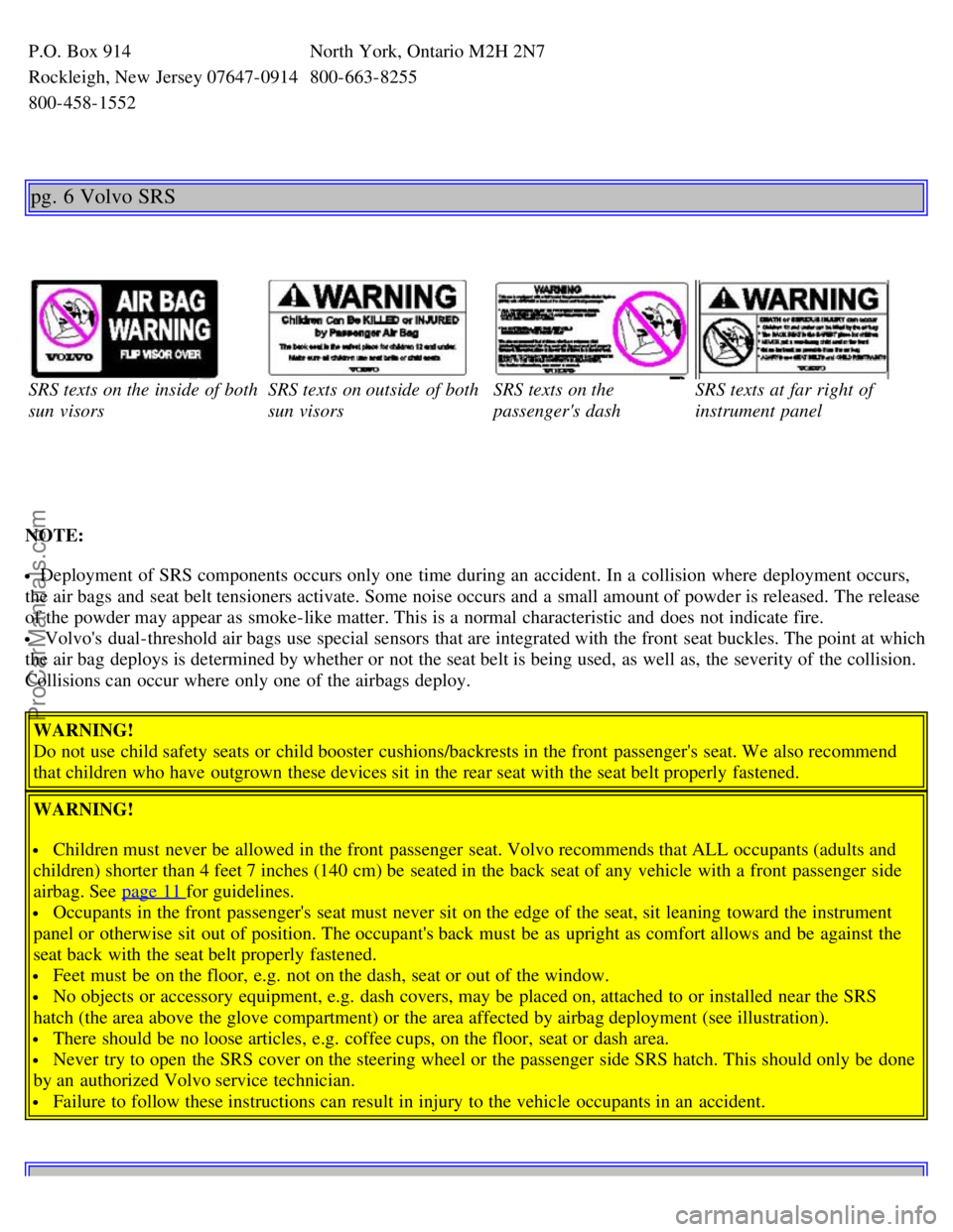
There is no maintenance to perform on the SRS yourself. The month and year shown on the decal on the door pillar
indicate when you should contact your Volvo retailer for specific servicing or replacement of airbags and seat belt
tensioners. This service must be performed by an authorized Volvo retailer.
Should you have any questions about the SRS system, please contact
your authorized Volvo retailer or Volvo Customer Support:
In the USA: In Canada:
Volvo Cars of North America, LLC. Volvo Canada Ltd.
Customer Relations 175 Gordon Baker Road
ProCarManuals.com
Page 10 of 98
P.O. Box 914North York, Ontario M2H 2N7
Rockleigh, New Jersey 07647-0914800-663-8255
800-458-1552
pg. 6 Volvo SRS
SRS texts on the inside of both
sun visorsSRS texts on outside of both
sun visorsSRS texts on the
passenger's dashSRS texts at far right of
instrument panel
NOTE:
Deployment of SRS components occurs only one time during an accident. In a collision where deployment occurs,
the air bags and seat belt tensioners activate. Some noise occurs and a small amount of powder is released. The release
of the powder may appear as smoke-like matter. This is a normal characteristic and does not indicate fire.
Volvo's dual-threshold air bags use special sensors that are integrated with the front seat buckles. The point at which
the air bag deploys is determined by whether or not the seat belt is being used, as well as, the severity of the collision.
Collisions can occur where only one of the airbags deploy.
WARNING!
Do not use child safety seats or child booster cushions/backrests in the front passenger's seat. We also recommend
that children who have outgrown these devices sit in the rear seat with the seat belt properly fastened.
WARNING!
Children must never be allowed in the front passenger seat. Volvo recommends that ALL occupants (adults and
children) shorter than 4 feet 7 inches (140 cm) be seated in the back seat of any vehicle with a front passenger side
airbag. See page 11
for guidelines.
Occupants in the front passenger's seat must never sit on the edge of the seat, sit leaning toward the instrument
panel or otherwise sit out of position. The occupant's back must be as upright as comfort allows and be against the
seat back with the seat belt properly fastened.
Feet must be on the floor, e.g. not on the dash, seat or out of the window.
No objects or accessory equipment, e.g. dash covers, may be placed on, attached to or installed near the SRS
hatch (the area above the glove compartment) or the area affected by airbag deployment (see illustration).
There should be no loose articles, e.g. coffee cups, on the floor, seat or dash area.
Never try to open the SRS cover on the steering wheel or the passenger side SRS hatch. This should only be done
by an authorized Volvo service technician.
Failure to follow these instructions can result in injury to the vehicle occupants in an accident.
ProCarManuals.com
Page 12 of 98
While holding the override button down, move the gear selector from the park position.
WARNING!
Never drive with the airbags deployed. The fact that they hang out can impair the steering of your car. Other safety
systems can also be damaged. The smoke and dust formed when the airbags are deployed can cause skin and eye
irritation in the event of prolonged exposure.
Contents | Top of Page
ProCarManuals.com
Page 14 of 98

6Space for additional equipment
7Space for additional equipment
8 Instruments 14-15
9Stability Control System - STC 23
10Trip computer (optional) 26-28
11Electrically operated convertible top 40
12Rear window demister/heated door mirrors 23
13Air mix 33
14Air vents 33
15Passenger side air bag (SRS) hatch 4-6
16Air vents 33
17Hood release 54
18Turn signals, high/low beams, exterior courtesy lights 20
18Cruise control 29
19Adjustable steering wheel 32
20Windshield wiper/washer 21
21Heated front seats (optional) 30
22Auxiliary socket 31
23Audio systems 133
24Heating and ventilation controls 33-35
25Hazard warning flashers 23
26Ashtray 31
27Coin holder 42
28Shiftlock release button (automatic transmission only) 101
29Gear selector shift positions 65-67
30Winter mode selector 67
31Parking brake 30
32Horn/SRS 4-6
33Trunk open control 55
34Power window controls 36
35Power mirror controls 51
36Fuel tank open control 37
37Central locking button 36
Some of the items above are available on certain models only.
pg. 16 Instruments
ProCarManuals.com
Page 20 of 98

With the headlight switch in position the parking lights will stay on (headlights off) with the daytime running light
screw (A) in position
.
The high beams can only be switched on if the headlight switch is in position
.
Switch from high to low beams and vice versa by moving the turn signal switch lever on the left side of steering
column towards the steering wheel.
* See page 26
for information on Daytime running lights.
Exterior courtesy lights
When you leave your car at night, you can make use of the exterior courtesy lighting function:
Remove the key from the ignition switch.
Pull the direction indicator lever towards the steering wheel (as when using the headlight flasher function).
The low beam headlights will now remain on for 30 seconds to light your way.
Turn signals
1 Lane change position. In maneuvers such as lane changing, the driver can flash the turn signals by moving the turn
signal lever to the first stop and holding it there. The lever will return to the neutral position when released.
2 Signal lever engaged for normal turns.
3 High beam/low beam switch (headlights on).
Move the lever towards the steering wheel and release it.
Headlight flasher (headlights off).
Move the lever towards the steering wheel. The headlight high beam will be on until the lever is released.
NOTE: A defective turn signal bulb will cause the turn signal indicator and remaining signal lights to flash more
rapidly than normal.
pg. 21 Windshield wipers/washers, Ignition switch
ProCarManuals.com
Page 21 of 98

Windshield wipers/washers
1 Intermittent wiper
With the switch in this position, the wipers will sweep approximately every seventh second.
2 "Single sweep" position:
The switch returns automatically when released.
3 Wipers, normal speed
4 Wipers, high speed
5 Windshield wiper/washer, headlight wiper/washer
The wipers will make 23 sweeps across the windshield and headlights (certain models) after the lever is released.
O Locked position: Remove the key to lock the steering wheel*
WARNING!
Never turn the key to position O while driving or when the car is being towed.
I Intermediate position**: Certain accessories, radio, etc. on, daytime running lights off.
II Drive position: Key position when engine is running.
III Starting position: Release the key when the engine starts. The key returns automatically to the Drive
position.
* On cars equipped with an automatic transmission the gear selector must also be in the (P)ark position.
** Please be aware that leaving the key in this position will increase battery drain.
Starting (ignition) switch/steering wheel lock
If you find it difficult to insert the key in the ignition or to move the steering wheel, the steering wheel lock might be
under tension. Turn the wheel back and forth slightly to free the ignition key.
In order to reduce car theft, make sure the steering wheel lock is engaged before leaving the car.
A chime will sound if the starting key is left in the ignition lock and the front door on the driver's side is opened.
WARNING!
Never switch off the ignition (turn the ignition key to position 0) or remove the key from the ignition switch while
the car is in motion. This could cause the steering wheel to lock, which would make the car impossible to steer.
pg. 22 Instrument illumination, Fog lights
ProCarManuals.com
Page 26 of 98

1 Glove compartment
2 Shelf under glove compartment
3 Coin holder
4 Compartment in door
5 Pocket on rear of front seat
6 Compartment between front seats
7 Cup holder
pg. 43 Keys, doors and locks
Master key
This key operates all locks (ignition switch/steering wheel lock, driver's door, trunk and glove compartment).
Service key
This key operates the driver's door and the ignition switch/steering wheel lock.
Doors and locks
Your car is equipped with a central locking system. The key, used on the driver's door, the remote control or central
locking button, will lock/unlock both doors and the trunk.
Turn the key once to unlock the driver's door only.
Turn the key again (within 10 seconds) to unlock both doors and the trunk.
ProCarManuals.com
Page 39 of 98
pedal for the first few minutes of operation. A cold engine uses more fuel and is subject to increased wear.
Whenever possible, avoid using the car for driving short distances. This does not allow the engine to reach normal
operating temperature.
Drive carefully and avoid rapid acceleration and hard braking.
Do not exceed speed limit.
Avoid carrying unnecessary items (extra load) in the car.
Maintain correct tire pressure. Check tire pressure regularly (check when tires are cold).
Remove snow tires when threat of snow or ice has ended.
Note that trunk-mounted luggage racks increase air resistance and thereby fuel consumption.
Avoid using automatic transmission kickdown feature unless necessary.
Avoid using the air conditioning when it is not required. When engaged, the air conditioner's compressor places an
additional load on the engine. However, please note that fuel consumption is lower with the air conditioning on than it
is when driving with the air conditioning switched off and the windows down.
If your car is equipped with the optional Trip Computer, utilizing the fuel consumption modes can help you "learn"
how to drive more economically.
Other factors which decrease gas mileage are:
Dirty air cleaner
Dirty engine oil and clogged oil filter
Dragging brakes
Incorrect front end alignment
Some of the above mentioned items and others are checked at the standard Maintenance Service intervals.
NOTE : (D)rive or 5th gear (manual transmissions) should be used as often as possible to help improve fuel economy.
pg. 64 Starting the Engine
Starting and stopping
1. Fasten the seat belt.
WARNING!
Before starting, check that the seat, steering wheel and mirrors are adjusted properly. Make sure the brake pedal can
be depressed completely. Move the seat closer if necessary. Refer to section "front seats".
2. Apply the parking brake, if not already set. The gear selector (automatic transmission) is locked in the (P)ark
position (SHIFT LOCK).
Manual transmission: the clutch must be fully depressed.
3. Without touching the accelerator pedal, turn the ignition key to the starting position*. Allow the starter to operate
for up to 10 seconds. Release the key as soon as the engine starts. If the engine fails to start, repeat step 3.
For cold starts at altitudes above 6000 ft (1800 meters), depress the accelerator pedal halfway and turn the key to the
starting position. Release the pedal slowly when the engine starts.
4. To release the gear selector from the (P)ark position (automatic transmission), the ignition key must be in position II
ProCarManuals.com
Page 63 of 98

2 0 0 3
VOLVO C70
Chapter 8 - Volvo Service
pg. 109 Volvo Service
Page
Label information 110
Maintenance service, Warranty111
Servicing112
Emissions maintenance113
Fuel/emissions systems114
Lubrication115
Engine oil116
Power steering fluid, Brake/clutch system fluid reservoir118
Washer fluid reservoir119
Coolant120
Engine compartment121
Battery maintenance/ Proposition 65 Warning122
Three-way catalytic converter123
pg. 110 Label information
1 Vehicle Emission Control Information
Your Volvo is designed to meet all applicable emission standards, as evidenced by the certification label on the
underside of the hood. For further information regarding these regulations, please consult your Volvo retailer.
2 Vacuum hose routing
(underside of hood)
3 Loads and Tire Pressures
(on rear edge of passenger's door)
4 Model plate
Vehicle Identification Number (VIN). Codes for color and upholstery, etc. This plate is located in the engine
compartment, on the inside of the left front fender.
5 Vehicle Identification Number (VIN) *
ProCarManuals.com