Message VOLVO S60 2016 Owner´s Manual
[x] Cancel search | Manufacturer: VOLVO, Model Year: 2016, Model line: S60, Model: VOLVO S60 2016Pages: 392, PDF Size: 10.04 MB
Page 88 of 392
||
03 Instruments and controls
03
86* Option/accessory, for more information, see Introduction.
NOTE
This function is only active in twilight or dark conditions, and only when the vehicleis in motion.
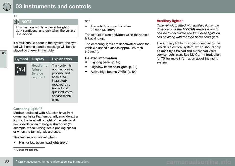
If a fault should occur in the system, the sym- bol will illuminate and a message will be dis-played as shown in the table.
SymbolDisplayExplanation
Headlamp failureServicerequiredThe system is not functioningproperly andshould beinspected/repaired by atrained andqualified Volvoservice techni-cian.
Cornering lights 18Models equipped with ABL also have front cornering lights that temporarily provide extralight to the front left or right of the vehicle atlow speeds when making a sharp turn (forexample, when turning into a parking space)or when the turn signals are used. This feature is activated when: •
High or low beam headlights are on and
• The vehicle's speed is below 20 mph (30 km/h)
The feature is also activated when the vehicle is backing up. The cornering lights are deactivated when the vehicle's speed exceeds approx. 25 mph(40 km/h).
Related information
• Lighting panel (p. 82)
• High/low beam headlights (p. 83)
• Active high beams (AHB)* (p. 84)
Auxiliary lights*
If the vehicle is fitted with auxiliary lights, the driver can use the
MY CAR menu system to
choose to deactivate and turn these lights onand off along with the high beam headlights. The auxiliary lights must be connected to the vehicle's electrical system, which should onlybe done by a trained and authorized Volvoservice technician. See My Car – introduction(p. 70) for more information about the menusystem.
18 Certain models only
Page 95 of 392
03 Instruments and controls
03
* Option/accessory, for more information, see Introduction.93
DeactivatingDeactivate the rain sensor by pressing the button
or press the lever down to
another wiper position. The rain sensor is automatically deactivated when the key is removed from the ignitionslot or five minutes after the ignition has beenswitched off.
CAUTION
The rain sensor should be deactivated when washing the car in an automatic carwash, etc. If the rain sensor function is lefton, the wipers will start inadvertently in thecar wash and could be damaged.
Windshield washer
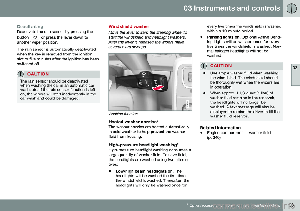
Move the lever toward the steering wheel to start the windshield and headlight washers.After the lever is released the wipers makeseveral extra sweeps.
Washing function
Heated washer nozzles*The washer nozzles are heated automatically in cold weather to help prevent the washerfluid from freezing.
High-pressure headlight washing*High-pressure headlight washing consumes alarge quantity of washer fluid. To save fluid,the headlights are washed using two alterna-tives:
• Low/high beam headlights on.
The
headlights will be washed the first time the windshield is washed. Thereafter, theheadlights will only be washed once for every five times the windshield is washedwithin a 10-minute period.
• Parking lights on.
Optional Active Bend-
ing Lights will be washed once for everyfive times the windshield is washed. Nor-mal halogen headlights will not bewashed.
CAUTION
• Use ample washer fluid when washing the windshield. The windshield shouldbe thoroughly wet when the wipers arein operation.
• When approx. 1 US quart (1 liter) ofwasher fluid remains in the reservoir,the headlights will no longer bewashed. A text message will also bedisplayed to remind the driver to fill thewasher fluid reservoir.
Related information
•
Engine compartment – washer fluid (p. 340)
Page 109 of 392
03 Instruments and controls
03
* Option/accessory, for more information, see Introduction.107
Information display – menu controls
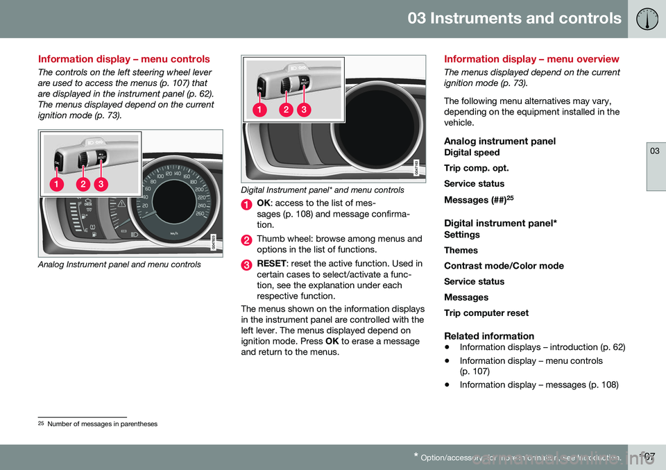
The controls on the left steering wheel lever are used to access the menus (p. 107) thatare displayed in the instrument panel (p. 62).The menus displayed depend on the currentignition mode (p. 73).
Analog Instrument panel and menu controls
Digital Instrument panel* and menu controls
OK : access to the list of mes-
sages (p. 108) and message confirma- tion.
Thumb wheel: browse among menus and options in the list of functions.
RESET : reset the active function. Used in
certain cases to select/activate a func- tion, see the explanation under eachrespective function.
The menus shown on the information displaysin the instrument panel are controlled with theleft lever. The menus displayed depend onignition mode. Press OK to erase a message
and return to the menus.
Information display – menu overview
The menus displayed depend on the current ignition mode (p. 73). The following menu alternatives may vary, depending on the equipment installed in thevehicle.
Analog instrument panelDigital speed Trip comp. opt.Service status
Messages (##) 25
Digital instrument panel*
Settings
Themes
Contrast mode /Color mode
Service status
Messages Trip computer reset
Related information
• Information displays – introduction (p. 62)
• Information display – menu controls (p. 107)
• Information display – messages (p. 108)
25
Number of messages in parentheses
Page 110 of 392
03 Instruments and controls
03
108
Information display – messages
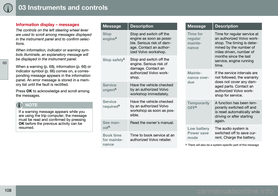
The controls on the left steering wheel lever are used to scroll among messages displayedin the instrument panel and to confirm selec-tions. When information, indicator or warning sym- bols illuminate, an explanatory message willbe displayed in the instrument panel. When a warning (p. 68), information (p. 66) or indicator symbol (p. 66) comes on, a corres-ponding message appears in the informationpanel. An error message is stored in a mem-ory list until the fault is rectified. Press OK to acknowledge and scroll among
the messages.
NOTE
If a warning message appears while you are using the trip computer, the messagemust be read and confirmed by pressingOK before the previous activity can be
resumed.
MessageDescription
Stop engineAStop and switch off the engine as soon as possi-ble. Serious risk of dam-age. Contact an author-ized Volvo workshop.
Stop safelyAStop and switch off the engine. Serious risk ofdamage. Contact anauthorized Volvo work-shop.
Service urgentAHave the vehicle checked by an authorized Volvoworkshop immediately.
Service requiredAHave the vehicle checked by an authorized Volvoworkshop as soon as pos-sible.
See man- ualARead the owner's manual.
Book time for mainte-nanceTime to book service at an authorized Volvo retailer.
MessageDescription
Time for regularmainte-nanceTime for regular service at an authorized Volvo work-shop. The timing is deter-mined by the number ofmiles driven, number ofmonths since the lastservice, engine runningtime.
Mainte- nance over-dueIf the service intervals are not followed, the warrantydoes not cover any dam-aged parts. Contact anauthorized Volvo work-shop for service.
Temporarily OFFAA function has been tem- porarily switched off andis reset automatically whiledriving or after startingagain.
Low battery Power savemodeThe audio system is switched off to save cur-rent. Charge the battery.
A There will also be a system-specific part of this message
Page 111 of 392
03 Instruments and controls
03
109
Related information
•Information displays – introduction (p. 62)
• Information display – menu overview (p. 107)
• Information display – menu controls(p. 107)
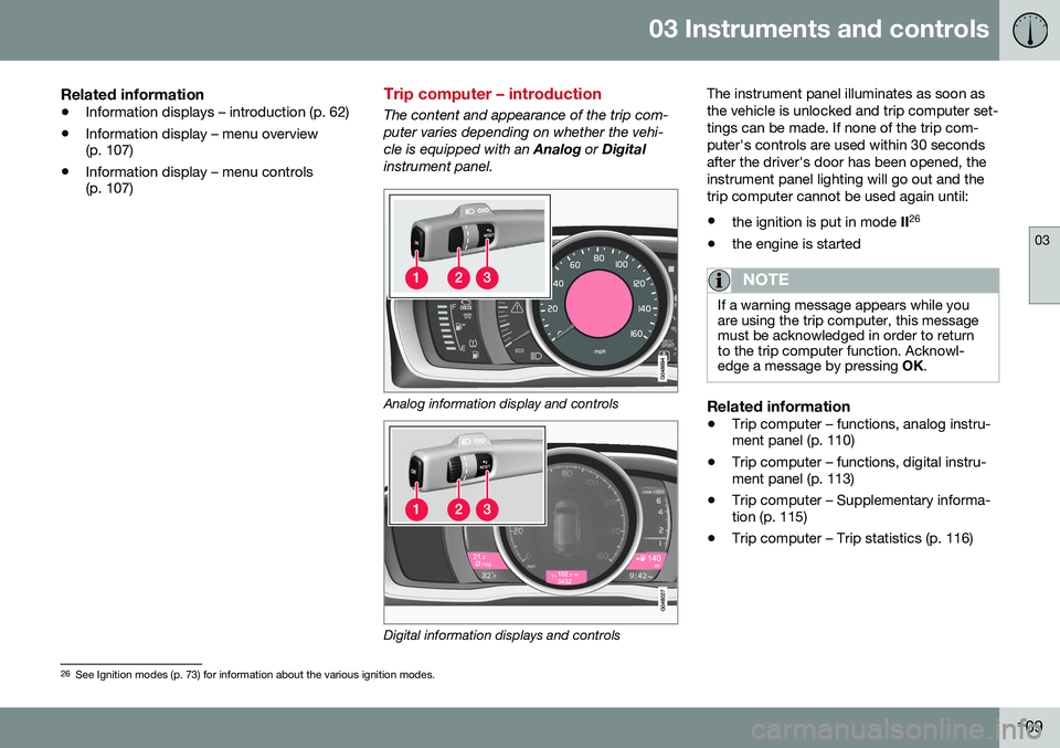
Trip computer – introduction
The content and appearance of the trip com- puter varies depending on whether the vehi-cle is equipped with an
Analog or Digital
instrument panel.
Analog information display and controls
Digital information displays and controls The instrument panel illuminates as soon as the vehicle is unlocked and trip computer set-tings can be made. If none of the trip com-puter's controls are used within 30 secondsafter the driver's door has been opened, theinstrument panel lighting will go out and thetrip computer cannot be used again until: •
the ignition is put in mode II26
• the engine is started
NOTE
If a warning message appears while you are using the trip computer, this messagemust be acknowledged in order to returnto the trip computer function. Acknowl-edge a message by pressing
OK.
Related information
• Trip computer – functions, analog instru- ment panel (p. 110)
• Trip computer – functions, digital instru-ment panel (p. 113)
• Trip computer – Supplementary informa-tion (p. 115)
• Trip computer – Trip statistics (p. 116)
26
See Ignition modes (p. 73) for information about the various ignition modes.
Page 112 of 392
03 Instruments and controls
03
110
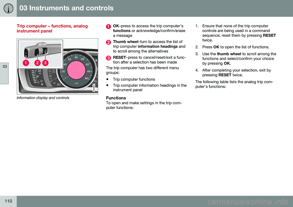
Trip computer – functions, analog instrument panel
Information display and controls
OK–press to access the trip computer's
functions or acknowledge/confirm/erase
a message
Thumb wheel –turn to access the list of
trip computer information headings and
to scroll among the alternatives
RESET –press to cancel/reset/exit a func-
tion after a selection has been made
The trip computer has two different menu groups:
• Trip computer functions
• Trip computer information headings in the instrument panel
FunctionsTo open and make settings in the trip com- puter functions: 1. Ensure that none of the trip computer
controls are being used in a commandsequence; reset them by pressing RESET
twice.
2. Press OK to open the list of functions.
3. Use the thumb wheel to scroll among the
functions and select/confirm your choiceby pressing OK.
4. After completing your selection, exit by pressing RESET twice.
The following table lists the analog trip com-puter's functions:
Page 113 of 392
03 Instruments and controls
03
}}
111
FunctionDescription
Digital speed – km/h – mph– NoneThis displays the vehicle's speed digitally in the center of the instrument panel
• Open by pressing
OK, scroll using the thumb wheel, confirm by pressing OK and exit by pressing
ENTER .
Trip comp. opt.
–
Distance to empty
– Fuel consumption
– Average speed
– Trip odometer T1 and total dist.
– Trip odometer T2 and total dist.
Selections among the trip computer information headings are made here. The symbols that have already been selected have a check mark and are displayed in white. Those not selected are not checked and
are displayed in gray:
1. Open the function by pressing OK and scroll to the desired heading using the thumb wheel.
2. Confirm by pressing OK. The symbol will change colors from gray to white and will be checked.
3. Continue this procedure or exit by pressing RESET.
Service statusShows the number of months and mileage until the next scheduled service.
Messages (##)For additional information, see Information display – menu controls (p. 107).
Information headingsAny of the information headings in the follow- ing table can be displayed. To do so:
1. Ensure that none of the trip computer
controls are being used in a command sequence; reset them by pressing RESET
twice. 2. Turn the
thumb wheel to begin display-
ing the information headings. Stop on thedesired heading.
3. See the table for an explanation of the heading or the actions that can be taken.
Page 115 of 392
03 Instruments and controls
03
}}
* Option/accessory, for more information, see Introduction.113
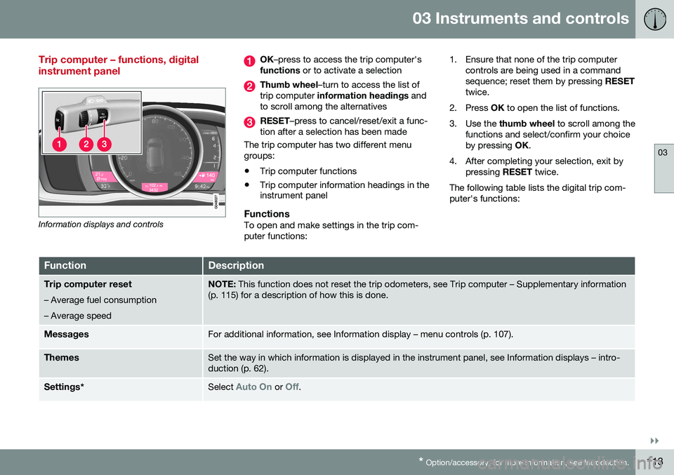
Trip computer – functions, digital instrument panel
Information displays and controls
OK –press to access the trip computer's
functions or to activate a selection
Thumb wheel –turn to access the list of
trip computer information headings and
to scroll among the alternatives
RESET –press to cancel/reset/exit a func-
tion after a selection has been made
The trip computer has two different menu groups:
• Trip computer functions
• Trip computer information headings in the instrument panel
FunctionsTo open and make settings in the trip com- puter functions: 1. Ensure that none of the trip computer
controls are being used in a commandsequence; reset them by pressing RESET
twice.
2. Press OK to open the list of functions.
3. Use the thumb wheel to scroll among the
functions and select/confirm your choiceby pressing OK.
4. After completing your selection, exit by pressing RESET twice.
The following table lists the digital trip com-puter's functions:
FunctionDescription
Trip computer reset
– Average fuel consumption – Average speedNOTE: This function does not reset the trip odometers, see Trip computer – Supplementary information
(p. 115) for a description of how this is done.
MessagesFor additional information, see Information display – menu controls (p. 107).
ThemesSet the way in which information is displayed in the instrument panel, see Information displays – intro- duction (p. 62).
Settings *Select Auto On or Off.
Page 143 of 392
06 Locks and alarm
06
}}
141
Making a settingDifferent alternatives for locking/unlocking confirmation can be selected in the menus bypressing MY CAR on the center console con-
trol panel. • To activate visual confirmation: go to
SettingsCar settingsLight
settings and select Door lock
confirmation light and/or Unlock
confirmation light by pressing OK/
MENU .
• To activate audible confirmation: go to
SettingsCar settingsLock
settings and select Audible
confirmation by pressing OK/MENU.
For a description of the menu system, see My Car – introduction (p. 70).
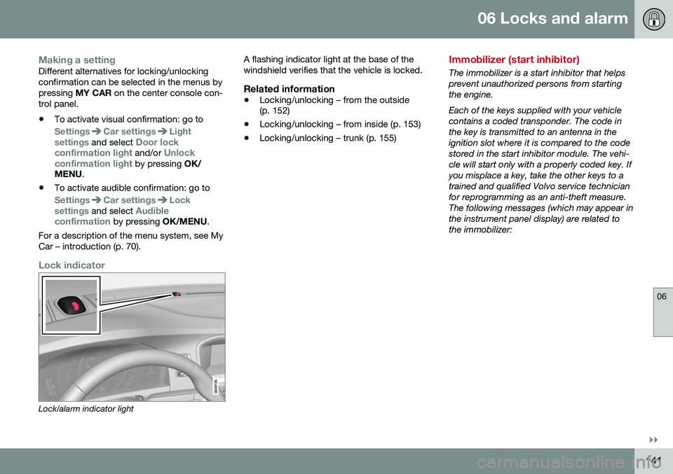
Lock indicator
Lock/alarm indicator light A flashing indicator light at the base of the windshield verifies that the vehicle is locked.
Related information
•
Locking/unlocking – from the outside (p. 152)
• Locking/unlocking – from inside (p. 153)
• Locking/unlocking – trunk (p. 155)
Immobilizer (start inhibitor)
The immobilizer is a start inhibitor that helps prevent unauthorized persons from startingthe engine. Each of the keys supplied with your vehicle contains a coded transponder. The code inthe key is transmitted to an antenna in theignition slot where it is compared to the codestored in the start inhibitor module. The vehi-cle will start only with a properly coded key. Ifyou misplace a key, take the other keys to atrained and qualified Volvo service technicianfor reprogramming as an anti-theft measure.The following messages (which may appear inthe instrument panel display) are related tothe immobilizer:
Page 144 of 392
||
06 Locks and alarm
06
142* Option/accessory, for more information, see Introduction.
MessageMeaning
Insert car keyRemote key not recognized during start. Try to start thevehicle again.
Car key not foundVehicles with keyless drive* only. Remote key not recog-nized during start. Try tostart the vehicle again. If the problem continues, insert the remote key into theignition slot and try to startthe vehicle again.
Immobil- izer TrystartagainRemote key fault during start. Contact an authorizedVolvo workshop.
CAUTION
Never use force when inserting the remote key in the ignition slot. The vehicle cannotbe started if the transponder is damaged.
USA–FCC ID: LTQWFS 125VO This device complies with part 15 of the FCC rules. Operation is subject to the followingcondition: (1) This device may not causeharmful interference, and (2) this device mustaccept any interference received, including interference that may cause undesired opera-tion. Canada–IC: 3659A-WFS125VOOperation is subject to the following condi- tions: (1) this device may not cause interfer-ence, and (2) this device must accept anyinterference, including interference that maycause undesired operation of the device. For information on starting the vehicle, see Starting the engine (p. 245).
Remote key – functions
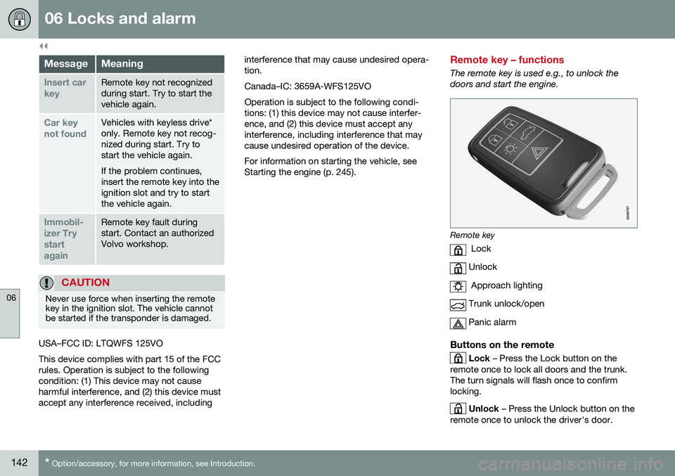
The remote key is used e.g., to unlock the doors and start the engine.
Remote key
Lock
Unlock
Approach lighting
Trunk unlock/open
Panic alarm
Buttons on the remote
Lock – Press the Lock button on the
remote once to lock all doors and the trunk. The turn signals will flash once to confirmlocking.
Unlock – Press the Unlock button on the
remote once to unlock the driver's door.