Message VOLVO S60 2016 Owner´s Manual
[x] Cancel search | Manufacturer: VOLVO, Model Year: 2016, Model line: S60, Model: VOLVO S60 2016Pages: 392, PDF Size: 10.04 MB
Page 145 of 392
06 Locks and alarm
06
* Option/accessory, for more information, see Introduction.143
After a short pause, press the Unlock button a second time within 10 seconds to unlockthe other doors and the trunk. This function can be changed so that all doors unlock at the same time by pressing My Car
and going to
SettingsCar
settings
Lock settingsChange doors
unlock setting. For a description of the menu
system, see My Car – introduction (p. 70).
Approach lighting – As you approach
the vehicle, press the button on the remote key to light the interior lighting, parking lights,license plate lighting and the lights in the doormirrors*. These lights will switch off automatically after 30, 60 or 90 seconds. For a description of themenu system, see My Car – introduction(p. 70).
Unlock/open trunk
Press once: This unlocks the trunk (but does
not open it) and disarms the alarm (the alarm indicator light on the dashboard will go out). Ifthe trunk is not opened within two minutes itwill automatically relock and the alarm will berearmed. Press twice: This both unlocks the trunk and
pops it open slightly.
NOTE
Any excess weight (snow, etc.) on the trunk lid may prevent it from opening.
For information on opening the trunk from the passenger compartment, see Locking/unlocking – trunk (p. 155). After closing, the trunk will not automatically relock. Press Lock to relock it and rearm thealarm.
Panic alarm – This button can be used
to attract attention during emergency situa- tions. To activate the panic alarm, press and hold this button for at least 3 seconds or press ittwice within 3 seconds. The turn signals andhorn will be activated. The panic alarm willstop automatically after 2 minutes and45 seconds. To deactivate, wait approximately 5 seconds and press the button again. The Panic alarm button will not unlock the vehicle.
Related information
• Locking/unlocking – from inside (p. 153)
• Locking/unlocking – from the outside (p. 152)
• Locking/unlocking confirmation (p. 140)
Remote key – range
The remote key has a range of approximately 60 ft. (20 m) from the vehicle.
NOTE
Buildings or other obstacles may interfere with the function of the remote key. Thevehicle can also be locked or unlockedwith the key blade, see Alarm-related func-tions (p. 160).
If the remote key is removed from the vehicle while the engine is running or if the ignition isin mode
I or II and all of the doors are closed,
a message will appear in the instrument paneldisplay and there will be an audible signal. When the remote key is returned to the vehi- cle, the message will be erased and the audi-ble signal will stop after one of the followinghas been done: • The remote key is inserted in the ignition slot
• The vehicle's speed exceeds 20 mph(30 km/h)
• The
OK button on the left steering wheel
lever is pressed
Related information
• Remote key – functions (p. 142)
Page 148 of 392
||
06 Locks and alarm
06
146
G021084
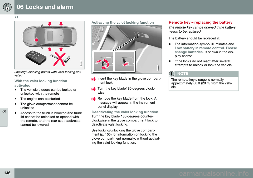
Locking/unlocking points with valet locking acti- vated
With the valet locking function
activated:
• The vehicle's doors can be locked or unlocked with the remote
• The engine can be started
• The glove compartment cannot beunlocked
• Access to the trunk is blocked (the trunklid cannot be unlocked or opened withthe remote, and the rear seat backrestscannot be lowered
Activating the valet locking function
Insert the key blade in the glove compart- ment lock.
Turn the key blade180 degrees clock- wise.
Remove the key blade from the lock. A message will appear in the instrumentpanel display.
Deactivating the valet locking functionTurn the key blade 180 degrees counter- clockwise in the glove compartment lock todeactivate valet locking. See locking/unlocking the glove compart- ment (p. 155) for information on locking theglove compartment normally, without activat-ing the valet locking function.
Remote key – replacing the battery
The remote key can be opened if the battery needs to be replaced. The battery should be replaced if:
• The information symbol illuminates and
Low battery in remote control. Please change batteries. is shown in the dis-
play and/or
• if the locks do not react after several attempts to unlock or lock the vehicle.
NOTE
The remote key's range is normally approximately 60 ft (20 m) from the vehi-cle.
Page 152 of 392
||
06 Locks and alarm
06
150* Option/accessory, for more information, see Introduction.
position of the driver's seat 2
and door mirrors
will be stored in the remote key's memory. The next time a door is opened by a person with the same remote key in his/her posses-
sion, the driver's seat and door mirrors willautomatically move to the position that theywere in when the door was most recentlylocked.
NOTE
If several people carrying remote keys approach the vehicle at the same time, thedriver's seat and door mirrors will assumethe positions they were in for the personwho opens the driver's door.
See also power seats (p. 75) for information on adjusting and storing the seat's position inthe seat memory.
NOTE
If the vehicle is locked by pressing the but- ton on one of the door handles or bypressing the lock button on the remotekey, or if it is left unlocked for more than30 minutes, the key memory function willbe deactivated. To reactivate the key's memory: • Unlock the vehicle by pulling a door handle with the remote key in yourpossession or by pressing the unlockbutton on the remote key.
Related information
•
Keyless drive*– locking/unlocking (p. 148)
• Remote key – functions (p. 142)
Keyless drive* – messages
If all of the remote keys are removed from the vehicle while the engine is running or if theignition modes (p. 73) is in mode
II and all of
the doors are closed, a message will appearin the instrument panel display and an audiblesignal will sound. When at least one remote key has been returned to the car, the message will beerased in the display and the audible signalwill stop when:
• A door has been opened and closed
• The remote key has been inserted in the ignition slot
• The
OK button has been pressed. For the
location of this button, see Informationdisplay – menu controls (p. 107)
2 Power seats only
Page 159 of 392
06 Locks and alarm
06
}}
157
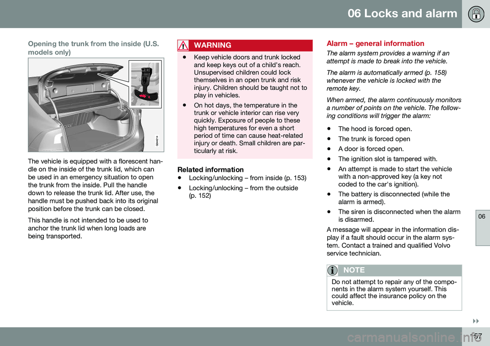
Opening the trunk from the inside (U.S. models only)
The vehicle is equipped with a florescent han- dle on the inside of the trunk lid, which canbe used in an emergency situation to openthe trunk from the inside. Pull the handledown to release the trunk lid. After use, thehandle must be pushed back into its originalposition before the trunk can be closed. This handle is not intended to be used to anchor the trunk lid when long loads arebeing transported.
WARNING
•Keep vehicle doors and trunk locked and keep keys out of a child’s reach.Unsupervised children could lockthemselves in an open trunk and riskinjury. Children should be taught not toplay in vehicles.
• On hot days, the temperature in thetrunk or vehicle interior can rise veryquickly. Exposure of people to thesehigh temperatures for even a shortperiod of time can cause heat-relatedinjury or death. Small children are par-ticularly at risk.
Related information
•
Locking/unlocking – from inside (p. 153)
• Locking/unlocking – from the outside (p. 152)
Alarm – general information
The alarm system provides a warning if an attempt is made to break into the vehicle. The alarm is automatically armed (p. 158) whenever the vehicle is locked with theremote key. When armed, the alarm continuously monitors a number of points on the vehicle. The follow-ing conditions will trigger the alarm:
• The hood is forced open.
• The trunk is forced open
• A door is forced open.
• The ignition slot is tampered with.
• An attempt is made to start the vehicle with a non-approved key (a key notcoded to the car's ignition).
• The battery is disconnected (while thealarm is armed).
• The siren is disconnected when the alarmis disarmed.
A message will appear in the information dis- play if a fault should occur in the alarm sys-tem. Contact a trained and qualified Volvoservice technician.
NOTE
Do not attempt to repair any of the compo- nents in the alarm system yourself. Thiscould affect the insurance policy on thevehicle.
Page 165 of 392
07 Driver support
07
}}
163
Spin Control (SC)The SC function is designed to help prevent the drive wheels from spinning while the vehi-cle is accelerating.
Active Yaw Control (AYC)This function helps maintain directional stabil- ity, for example when cornering, by brakingone or more of the wheels if the vehicleshows a tendency to skid or slide laterally.
Corner Traction Control (CTC)CTC compensates for understeering and helps provide additional stability when accel-erating through a curve by preventing theinside wheel from spinning. This is particularlyuseful when accelerating on a curving high-way on-ramp. CTC is most effective if the stability system's Sport mode is selected. See the section
about Sport mode.
Engine Drag Control (EDC)EDC helps keep the engine running if the wheels show a tendency to lock, e.g., whenshifting down in the Geartronic manual shift-ing mode or while using the engine's brakingfunction on a slippery surface. If the enginewere to stop, power steering would not func-tion, making the vehicle more difficult tosteer.
Trailer Stability Assist (TSA)The TSA helps stabilize a vehicle that is tow- ing a trailer when the vehicle and trailer have begun to sway. See Trailer Stability Assist(TSA) (p. 280) for more information. This system is automatically deactivated if the driver selects
Sport mode.
Related information
•Stability system – operation (p. 163)
• Stability system – symbols and messages (p. 165)
• Trailer Stability Assist (TSA) (p. 280)
Stability system – operation
Operation
Sport modeThe stability system is always activated and cannot be switched off.
However, the driver canselect Sport mode, which
offers more active drivingcharacteristics. Sport mode can be selected
in the MY CAR menus, see
My Car – introduction (p. 70).
In Sport mode, the engine management sys-
tem monitors movement of the accelerator pedal and steering wheel for sportier drivingby allowing more lateral movement of the rearwheels before ESC is activated. Under certain circumstances, such as when driving with snow chains, or driving in deepsnow or loose sand, it may be advisable totemporarily use Sport mode for maximum
tractive force. If the driver releases pressure on the acceler- ator pedal, ETC will also activate to help sta-bilize the vehicle. To switch to Sport mode:
Sport mode remains active until the driver
switches it off in the menu or until the engine is switched off. ETC will return to normalmode when the engine is restarted.
Page 166 of 392
||
07 Driver support
07
164
Related information
•Stability system – introduction (p. 162)
• Stability system – symbols and messages (p. 165)
Page 167 of 392
07 Driver support
07
}}
165
Stability system – symbols and messages
Symbols and messages in the main
instrument panel
A text message can be erased by pressing briefly the OK button on the turn signal lever.
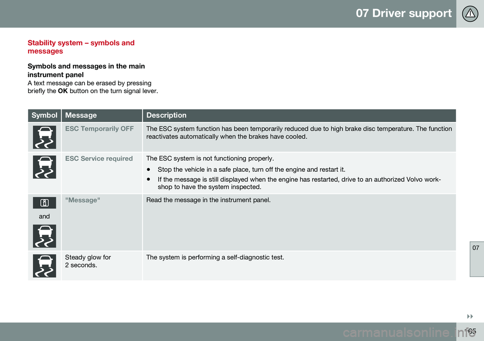
SymbolMessageDescription
ESC Temporarily OFFThe ESC system function has been temporarily reduced due to high brake disc temperature. The function reactivates automatically when the brakes have cooled.
ESC Service requiredThe ESC system is not functioning properly. • Stop the vehicle in a safe place, turn off the engine and restart it.
• If the message is still displayed when the engine has restarted, drive to an authorized Volvo work- shop to have the system inspected.
and
"Message"Read the message in the instrument panel.
Steady glow for 2 seconds.The system is performing a self-diagnostic test.
Page 168 of 392
||
07 Driver support
07
166
SymbolMessageDescription
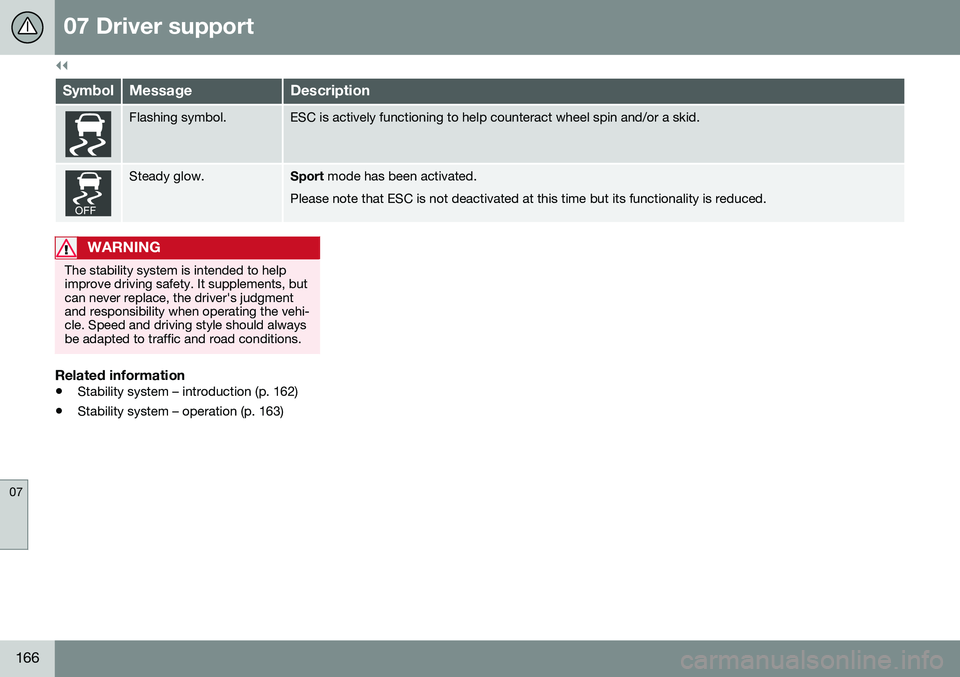
Flashing symbol.ESC is actively functioning to help counteract wheel spin and/or a skid.
Steady glow.Sport mode has been activated.
Please note that ESC is not deactivated at this time but its functionality is reduced.
WARNING
The stability system is intended to help improve driving safety. It supplements, butcan never replace, the driver's judgmentand responsibility when operating the vehi-cle. Speed and driving style should alwaysbe adapted to traffic and road conditions.
Related information
• Stability system – introduction (p. 162)
• Stability system – operation (p. 163)
Page 169 of 392
07 Driver support
07
* Option/accessory, for more information, see Introduction.167
Adjustable steering force*
Steering force increases with the speed of the vehicle to give the driver enhanced sense ofcontrol and stability. At low speed the vehicleis easy to steer in order to facilitate parking,etc.
Adjustable steering force*Steering force can be changed under MY
CAR
Car settingsSteering wheel
force
. Select Low, Medium or High. For a
description of the menu system, My Car – introduction (p. 70).
NOTE
This steering force level menu function cannot be accessed when the vehicle is inmotion.
NOTE
In certain situations, the power steering may become too warm and will have to betemporarily cooled down. While this ishappening, the power steering effect willbe reduced slightly and somewhat moreeffort may be required to turn the steeringwheel. If this occurs, a message will be displayed in the instrument panel.
Related information
• Active chassis* (Four C) (p. 162)
Road Sign Information (RSI)* – introduction
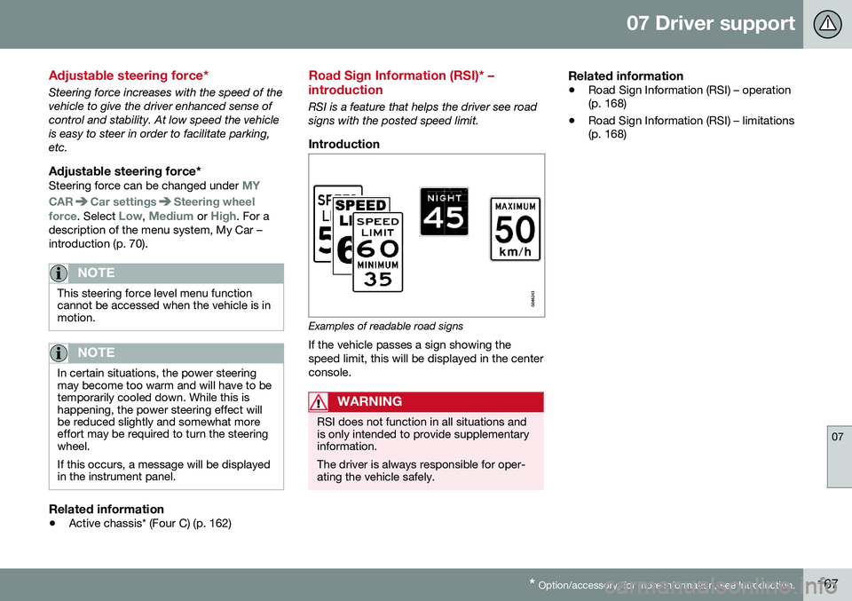
RSI is a feature that helps the driver see road signs with the posted speed limit.
Introduction
Examples of readable road signs If the vehicle passes a sign showing the speed limit, this will be displayed in the centerconsole.
WARNING
RSI does not function in all situations and is only intended to provide supplementaryinformation. The driver is always responsible for oper- ating the vehicle safely.
Related information
•Road Sign Information (RSI) – operation (p. 168)
• Road Sign Information (RSI) – limitations(p. 168)
Page 175 of 392
07 Driver support
07
}}
173
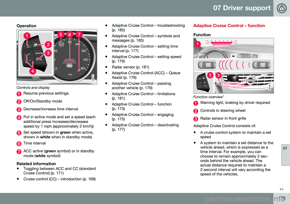
Operation
Controls and display
Resume previous settings.
Off/On/Standby mode
Decrease/increase time interval
Put in active mode and set a speed (each additional press increases/decreasesspeed by 1 mph (approximately 2 km/h))
Set speed (shown in green when active,
shown in white when in standby mode)
Time interval
ACC active ( green symbol) or in standby
mode ( white symbol)
Related information
•Toggling between ACC and CC (standard Cruise Control) (p. 171)
• Cruise control (CC) – introduction (p. 169) •
Adaptive Cruise Control – troubleshooting(p. 185)
• Adaptive Cruise Control – symbols andmessages (p. 183)
• Adaptive Cruise Control – setting timeinterval (p. 177)
• Adaptive Cruise Control – setting speed(p. 176)
• Radar sensor (p. 181)
• Adaptive Cruise Control (ACC) – QueueAssist (p. 179)
• Adaptive Cruise Control – passinganother vehicle (p. 179)
• Adaptive Cruise Control – limitations(p. 181)
• Adaptive Cruise Control – function(p. 173)
• Adaptive Cruise Control – engaging(p. 175)
• Adaptive Cruise Control – deactivating(p. 177)
Adaptive Cruise Control – function
Function
Function overview 1
Warning light, braking by driver required
Controls in steering wheel
Radar sensor in front grille
Adaptive Cruise Control consists of: • A cruise control system to maintain a set speed
• A system to maintain a set distance to thevehicle ahead, which is expressed as atime interval. For example, you canchoose to remain approximately 2 sec-onds behind the vehicle ahead. Theactual distance required to maintain a2-second interval will vary according thespeed of the vehicles.