sensor VOLVO S60 2017 Owner´s Manual
[x] Cancel search | Manufacturer: VOLVO, Model Year: 2017, Model line: S60, Model: VOLVO S60 2017Pages: 398, PDF Size: 9.46 MB
Page 245 of 398
DRIVER SUPPORT
243
WARNING
Keep in mind that the image on the screen only shows the area behind the vehicle. Thedriver must always watch for people, animals,other vehicles, etc., near the sides of the vehi-cle when turning while backing up.
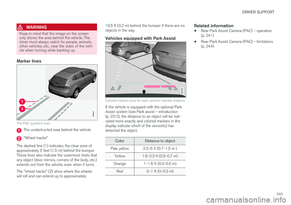
Marker lines
The PAC system's lines
The unobstructed area behind the vehicle
"Wheel tracks"
The dashed line (1) indicates the clear zone of approximately 5 feet (1.5 m) behind the bumper.These lines also indicate the outermost limits thatany object (door mirrors, corners of the body, etc.)extends out from the vehicle, even when it turns. The "wheel tracks" (2) show where the wheels will roll and can extend up to approximately 10.5 ft (3.2 m) behind the bumper if there are noobjects in the way.
Vehicles equipped with Park Assist
Colored markers (one for each sensor) indicate distance
If the vehicle is equipped with the optional Park Assist system (see Park assist – introduction(p. 231)), the distance to an object will be indi-cated more exactly and colored markers in thedisplay indicate which of the sensor(s) hasdetected the object.
ColorDistance to object
Pale yellow2.3–5 ft (0.7–1.5 m )
Yellow1.6–2.3 ft (0.5–0.7 m)
Orange1–1.6 ft (0.3–0.5 m)
Red0–1 ft (0–0.3 m)
Related information
•
Rear Park Assist Camera (PAC) – operation (p. 241)
• Rear Park Assist Camera (PAC) – limitations(p. 244)
Page 247 of 398

DRIVER SUPPORT
}}
* Option/accessory, for more information, see Introduction.245
WARNING
•BLIS and CTA are information systems, NOT warning or safety systems and donot function in all situations.
• BLIS and CTA do not eliminate the needfor you to visually confirm the conditionsaround you, and the need for you to turnyour head and shoulders to make surethat you can safely change lanes or backup.
• As the driver, you have full responsibilityfor changing lanes/backing up in a safemanner.
Radar sensor type approval
USA FCC ID: L2C0055TR Canada IC: 3432A-0055TR This device complies with Part 15 of the FCC Rules and with Industry Canada license-exemptRSS standard(s). Operation is subject to the fol-lowing two conditions: (1) This device may notcause harmful interference, and (2) This devicemust accept any interference received, includinginterference that may cause undesired operation. The term “IC:” before the radio certification num- ber only signifies that Industry Canada technicalspecifications were met.
WARNING
Changes or modifications not expressively approved by the party responsible for compli-ance could void the user's authority to oper-ate the equipment.
Related information
•
BLIS
* – function (p. 245)
• BLIS
* – operation (p. 246)
• BLIS
* – Cross Traffic Alert (CTA) (p. 247)
• BLIS
* – limitations (p. 248)
• BLIS
* – messages (p. 249)
BLIS * – function
When does BLIS functionThe system functions when your vehicle is mov- ing at speeds above 6 mph (10 km/h).
Zone 1. Blind area, Zone 2. Area for passing vehicles
BLIS is designed to react to: • Other vehicles in your door mirrors' "blind area"
• Vehicles that are passing your vehicle
When BLIS detects a vehicle in zone 1 or a pass-ing vehicle in zone 2, the indicator light in thedoor panel will glow steadily. If the driver thenuses the turn signal on the side on which thewarning is given, the indicator light will flash andbecome brighter.
Page 249 of 398
DRIVER SUPPORT
}}
* Option/accessory, for more information, see Introduction.247
BLIS* – Cross Traffic Alert (CTA)
Cross Traffic Alert (CTA) is a supplementary BLIS 15
function intended to detect vehicles
crossing behind your vehicle while you are back- ing up.
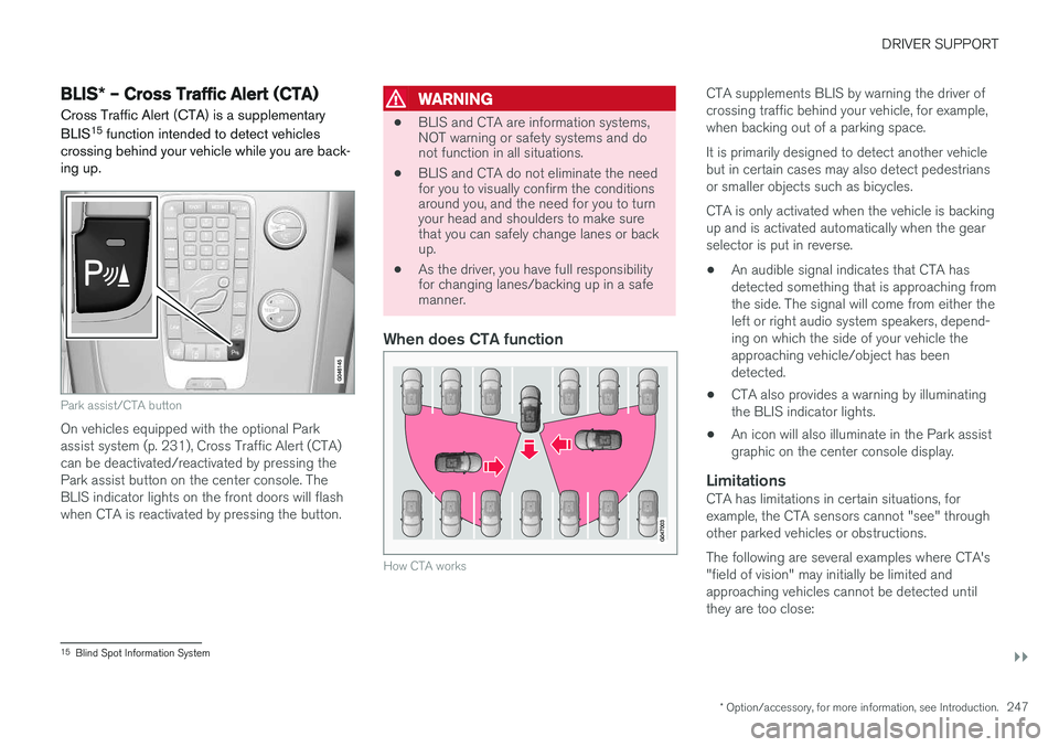
Park assist/CTA button
On vehicles equipped with the optional Park assist system (p. 231), Cross Traffic Alert (CTA)can be deactivated/reactivated by pressing thePark assist button on the center console. TheBLIS indicator lights on the front doors will flashwhen CTA is reactivated by pressing the button.
WARNING
• BLIS and CTA are information systems, NOT warning or safety systems and donot function in all situations.
• BLIS and CTA do not eliminate the needfor you to visually confirm the conditionsaround you, and the need for you to turnyour head and shoulders to make surethat you can safely change lanes or backup.
• As the driver, you have full responsibilityfor changing lanes/backing up in a safemanner.
When does CTA function
How CTA works
CTA supplements BLIS by warning the driver of crossing traffic behind your vehicle, for example,when backing out of a parking space. It is primarily designed to detect another vehicle but in certain cases may also detect pedestriansor smaller objects such as bicycles. CTA is only activated when the vehicle is backing up and is activated automatically when the gearselector is put in reverse.
• An audible signal indicates that CTA hasdetected something that is approaching fromthe side. The signal will come from either theleft or right audio system speakers, depend-ing on which the side of your vehicle theapproaching vehicle/object has beendetected.
• CTA also provides a warning by illuminatingthe BLIS indicator lights.
• An icon will also illuminate in the Park assistgraphic on the center console display.
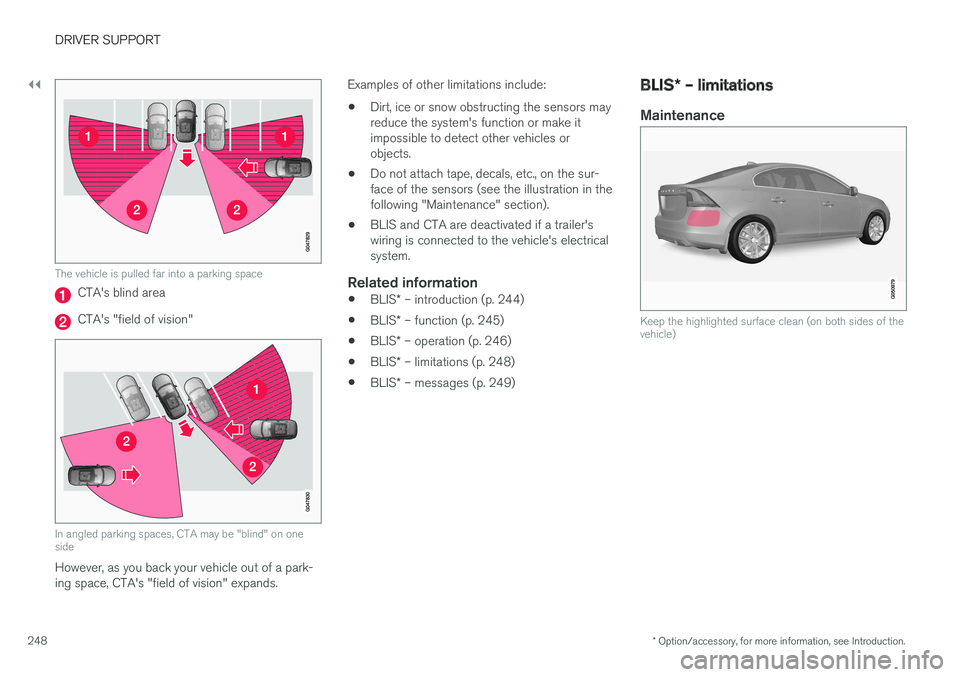
LimitationsCTA has limitations in certain situations, forexample, the CTA sensors cannot "see" throughother parked vehicles or obstructions. The following are several examples where CTA's "field of vision" may initially be limited andapproaching vehicles cannot be detected untilthey are too close:
15
Blind Spot Information System
Page 250 of 398
||
DRIVER SUPPORT
* Option/accessory, for more information, see Introduction.
248
The vehicle is pulled far into a parking space
CTA's blind area
CTA's "field of vision"
In angled parking spaces, CTA may be "blind" on one side
However, as you back your vehicle out of a park- ing space, CTA's "field of vision" expands. Examples of other limitations include:
• Dirt, ice or snow obstructing the sensors mayreduce the system's function or make itimpossible to detect other vehicles orobjects.
• Do not attach tape, decals, etc., on the sur-face of the sensors (see the illustration in thefollowing "Maintenance" section).
• BLIS and CTA are deactivated if a trailer'swiring is connected to the vehicle's electricalsystem.
Related information
•
BLIS
* – introduction (p. 244)
• BLIS
* – function (p. 245)
• BLIS
* – operation (p. 246)
• BLIS
* – limitations (p. 248)
• BLIS
* – messages (p. 249)
BLIS * – limitations
Maintenance
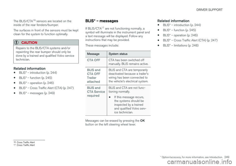
Keep the highlighted surface clean (on both sides of the vehicle)
Page 251 of 398
DRIVER SUPPORT
* Option/accessory, for more information, see Introduction.249
The BLIS/CTA
16
sensors are located on the
inside of the rear fenders/bumper. The surfaces in front of the sensors must be kept clean for the system to function optimally.
CAUTION
Repairs to the BLIS/CTA systems and/or repainting the rear bumper should only bedone by a trained and qualified Volvo servicetechnician.
Related information
• BLIS
* – introduction (p. 244)
• BLIS
* – function (p. 245)
• BLIS
* – operation (p. 246)
• BLIS
* – Cross Traffic Alert (CTA) (p. 247)
• BLIS
* – messages (p. 249)
BLIS * – messages
If BLIS/CTA 17
are not functioning normally, a
symbol will illuminate in the instrument panel and a text message will be displayed. Follow anyinstructions that may be provided. These messages include:
MessageSystem status
CTA OFFCTA has been switched off manually. BLIS remains active.
BLIS and CTA OFFTrailerattachedBLIS and CTA are temporarily deactivated because a trailer'swiring has been connected tothe vehicle's electrical system.
BLIS and CTA ServicerequiredBLIS and CTA are not func- tioning normally.
• If this message recurs,the systems should beinspected by a trainedand qualified Volvo serv-ice technician.
Messages can be erased by pressing the
OK
button on the left steering wheel lever.
Related information
• BLIS
* – introduction (p. 244)
• BLIS
* – function (p. 245)
• BLIS
* – operation (p. 246)
• BLIS
* – Cross Traffic Alert (CTA) (p. 247)
• BLIS
* – limitations (p. 248)
16
Cross Traffic Alert
17 Cross Traffic Alert
Page 281 of 398
STARTING AND DRIVING
}}
279
Driving in cold weather
Check your vehicle before the approach of cold weather.
The following advice is worth noting:
• Make sure that the engine coolant (p. 333) contains 50 percent antifreeze. Any othermixture will reduce freeze protection. Thisgives protection against freezing down to–31 °F (–35 °C). The use of "recycled" anti-freeze is not approved by Volvo. Differenttypes of antifreeze must not be mixed.
• Volvo recommends using only genuine Volvoantifreeze in your vehicle's radiator.
• Try to keep the fuel tank well filled – thishelps prevent the formation of condensationin the tank. In addition, in extremely coldweather conditions it is worthwhile to addfuel line de-icer before refueling.
• The viscosity of the engine oil is important.Oil with low viscosity (thinner oil) improvescold-weather starting as well as decreasingfuel consumption while the engine is warm-ing up. Full synthetic 0W-30 oil is recom-mended for driving in areas with sustainedlow temperatures.
• The load placed on the battery is greater dur-ing the winter since the windshield wipers,lighting, etc., are used more often. Moreover,the capacity of the battery decreases as thetemperature drops. In very cold weather, apoorly charged battery can freeze and be damaged. It is therefore advisable to checkthe state of charge more frequently andspray an anti-rust oil on the battery posts.
• Volvo recommends the use of snow tires onall four wheels for winter driving, see Snowtires/studded tires (p. 308).
• To prevent the washer fluid (p. 346)reservoirfrom freezing, add washer solvents contain-ing antifreeze. This is important since dirt isoften splashed on the windshield during win-ter driving, requiring the frequent use of thewashers and wipers. Volvo Washer Solventshould be diluted as follows: Down to 14 °F(–10 °C): 1 part washer solvent and 4 partswater Down to 5 °F (–15 °C): 1 part washersolvent and 3 parts water Down to 0 °F(–18 °C): 1 part washer solvent and 2 partswater Down to –18 °F (–28 °C): 1 partwasher solvent and 1 part water.
• Use Volvo Teflon Lock Spray in the locks.
• Avoid using de-icing sprays as they cancause damage to the locks.
Refueling – fuel requirements
Volvo recommends the use of detergent gaso- line to control engine deposits.
Deposit control gasoline (detergent
additives)
Detergent gasoline is effective in keeping injec- tors and intake valves clean. Consistent use ofdeposit control gasolines will help ensure gooddrivability and fuel economy. If you are not surewhether the gasoline contains deposit controladditives, check with the service station operator.
NOTE
Volvo does not recommend the use of exter- nal fuel injector cleaning systems.
Unleaded fuelEach Volvo has a three-way catalytic converter and must use only unleaded gasoline. U.S. andCanadian regulations require that pumps deliver-ing unleaded gasoline be labeled "UNLEADED".Only these pumps have nozzles which fit yourvehicle's filler inlet. It is unlawful to dispense lea-ded fuel into a vehicle labeled "unleaded gaso-line only". Leaded gasoline damages the three-way catalytic converter and the heated oxygensensor system. Repeated use of leaded gasolinewill lessen the effectiveness of the emission con-trol system (p. 283) and could result in loss ofemission warranty coverage. State and local vehi-
Page 286 of 398
||
STARTING AND DRIVING
* Option/accessory, for more information, see Introduction.
284 nents, altering emission system components or location or removing components, and/orrepeated use of leaded fuel.
NOTE
Unleaded fuel is required for vehicles with three-way catalytic converters.
Heated oxygen sensorsThe heated oxygen sensors monitor the oxygen content of the exhaust gases. Readings are fedinto a control module that continuously monitorsengine functions and controls fuel injection. Theratio of fuel to air into the engine is continuouslyadjusted for efficient combustion to help reduceharmful emissions.
Related information
•
Information displays – warning symbols(p. 69)
• Engine and cooling system (p. 277)
Economical driving
Better driving economy may be obtained by thinking ahead, avoiding rapid starts and stopsand adjusting the speed of your vehicle to imme-diate traffic conditions.
Economical driving conserves natural
resources
Observe the following rules: • Bring the engine to normal operating tem- perature as soon as possible by driving witha light foot on the accelerator pedal for thefirst few minutes of operation. A cold engineuses more fuel and is subject to increasedwear.
• Whenever possible, avoid using the vehiclefor driving short distances. This does notallow the engine to reach normal operatingtemperature.
• Drive carefully and avoid rapid accelerationand hard braking.
• Use the transmission's Drive (
D) position as
often as possible and avoid using kick-down.
• Using the transmission's Sport mode 13
may
increase fuel consumption somewhat. Use the transmission's Drive ( D) position as often
as possible. For additional information about Sport mode, see Transmission – Geartronic(p. 258). •
Using the engine's optional Eco function canhelp improve fuel economy. For additional information, see ECO
* (p. 267).
• Do not exceed posted speed limits.
• Avoid carrying unnecessary items (extra load) in the vehicle.
• Maintain correct tire pressure. Check tirepressure regularly (when tires are cold).
• Remove snow tires when threat of snow orice has ended.
• Note that roof racks, ski racks, etc, increaseair resistance and also fuel consumption.
• At highway driving speeds, fuel consumptionwill be lower with the air conditioning on andthe windows closed than with the air condi-tioning off and the windows open.
• Using the onboard trip computer's fuel con-sumption modes can help you learn how todrive more economically.
Other factors that decrease gas mileage are:
• Dirty air cleaner
• Dirty engine oil and clogged oil filter
• Dragging brakes
• Incorrect front end alignment
13
Certain models only.
Page 311 of 398

WHEELS AND TIRES
}}
309
system that illuminates a low tire pressure telltale (
) when one or more of your tires is signifi-
cantly under-inflated. Accordingly, when the low tire pressure telltale illuminates, you should stopand check your tires as soon as possible, andinflate them to the proper pressure. Driving on a significantly under-inflated tire cau- ses the tire to overheat and can lead to tire fail-ure. Under-inflation also reduces fuel efficiencyand tire tread life, and may affect the vehicle'shandling and stopping ability. Please note that atire pressure monitoring system is not a substi-tute for proper tire maintenance, and it is the driv-er's responsibility to maintain correct tire pres-sure, even if under-inflation has not reached thelevel to trigger illumination of the system's lowtire pressure telltale. Your vehicle has also been equipped with a TPMS malfunction indicator to indicate when thesystem is not operating properly. The monitoringsystem's malfunction indicator is combined withthe low tire pressure telltale. When the system detects a malfunction, the tell- tale will flash for approximately one minute andthen remain continuously illuminated. Thissequence will continue upon subsequent vehiclestart-ups as long as the malfunction exists. Whenthe malfunction indicator is illuminated, the sys-tem may not be able to detect or signal low tirepressure as intended. System malfunctions may occur for a variety ofreasons, including the installation of replacementor alternate tires or wheels on the vehicle thatprevent the tire pressure monitoring system fromfunctioning properly. Always check the system's malfunction telltale after replacing one or more tires or wheels onyour vehicle to ensure that the replacement oralternate tires and wheels allow the system tocontinue to function properly.
NOTE
The system indicates low tire pressure but does not replace normal tire maintenance. Forinformation on correct tire pressure, pleaserefer to the tire inflation decal on the driver'sdoor opening or consult your Volvo retailer.
WARNING
Incorrect inflation pressure could lead to tire failure, resulting in a loss of control of thevehicle.
Related information
•
Tire Monitor - introduction (p. 309)
• Tire Pressure Monitoring System (TPMS) – general information (p. 312)
Tire Monitor - introduction Tire Monitor uses the rotational speed of the tires in combination with signal analysis of theABS sensor signals to determine if they areproperly inflated.
When a tire is under-inflated, its diameter (and consequently also its rotational speed) changes.By comparing the individual tires with each otherit is possible to determine if one or more tires areunder inflated. When low inflation pressure is detected or if the system is not functioning properly, Tire Monitorwill light up the tire pressure warning light (
) (also referred to as a telltale) in the
instrument panel and will display one of several messages in the text window, for example:
Tire
pressure low Check tires. Adjust the inflation
pressure and recalibrate if necessary.
NOTE
If a malfunction occurs in the system, the tire pressure warning light will flash for approxi-mately 1 minute and then remain illuminated.
Tire press. syst Service required will be
displayed.
Page 314 of 398
||
WHEELS AND TIRES
312
NOTE
To help avoid incorrect tire inflation pressure, only inflate the tires when they are cold. Thetires are considered to be cold when theyhave the same temperature as the surround-ing (ambient) air. This temperature is normallyreached after the vehicle has been parked forat least 3 hours. After driving a distance ofapproximately 1 mile (1.6 km), the tires areconsidered to be hot.
CAUTION
•After inflating the tires, always reinstall the valve cap to help avoid damage to thevalve from dirt, gravel, etc.
• Use plastic valve caps only. Metal capscould corrode and become difficult toremove.
WARNING
•
Incorrect inflation pressure could lead to tire failure, resulting in a loss of control ofthe vehicle.
• Tire monitoring systems cannot indicatesudden tire damage caused by externalfactors (e.g., a blowout) in advance.
Related information
•Tire inflation – checking pressure (p. 301)
Tire Pressure Monitoring System (TPMS) – general information TPMS uses sensors mounted in the tire valves to check inflation pressure levels. When thevehicle is moving at a speed of approximately20 mph (30 km/h) or faster, these sensorstransmit inflation pressure data to a receiverlocated in the vehicle.
NOTE
USA – FCC ID: KR5S180052050 This device complies with part 15 of the FCC rules. Operation is subject to the followingconditions: (1) This device may not causeharmful interference, and (2) this device mustaccept any interference received, includinginterference that may cause undesired opera-tion.
When low inflation pressure is detected or if a sensor is not functioning properly, TPMS will light up the tire pressure warning light (
) (also
referred to as a telltale) in the instrument panel and will display one of the following messages:
Tire pressure low, Tire needs air now or Tire
press. syst Service required.
NOTE
If a malfunction occurs in the system, the tire pressure warning light will flash for approxi-mately 1 minute and then remain illuminated.
Tire press. syst Service required will be
displayed.
Related information
• Tire Pressure Monitoring System (TPMS) – recalibrating (p. 314)
• Tire Pressure Monitoring System (TPMS) –messages (p. 315)
• Tire Pressure Monitoring System (TPMS) –activating/deactivating (p. 314)
• Tire Pressure Monitoring System (TPMS) –changing wheels (p. 313)
Page 315 of 398

WHEELS AND TIRES
313
Tire Pressure Monitoring System (TPMS) – changing wheels
Please keep the following in mind when chang- ing or replacing the factory installed TPMSwheels/tires on the vehicle:
• Not all aftermarket wheels are equipped withTPMS sensors in the valves.
• If the vehicle is equipped with a temporaryspare tire, this tire does not have a TPMSsensor.
• If wheels without TPMS sensors are moun-ted on the vehicle, a text message will dis-played in the instrument panel each time thevehicle is driven above 20 mph (30 km/h) for10 minutes or more.
• Once TPMS sensors are properly installed,the warning message should not reappear. Ifthe message is still displayed, drive the vehi-cle for several minutes at a speed of 20 mph(30 km/h) or faster to erase the message.
• Volvo recommends that TPMS sensors befitted on all wheels used on the vehicle,including winter tires. Volvo does not recom-mend moving sensors back and forthbetween sets of wheels.
CAUTION
When inflating tires, press the pump's mouth- piece straight onto the valve to help avoidbending or otherwise damaging the valve.
CAUTION
•After inflating the tires, always reinstall the valve cap to help avoid damage to thevalve from dirt, gravel, etc.
• Use plastic valve caps only. Metal capscould corrode and become difficult toremove.
NOTE
•
If you change to tires with a different dimension than the factory-installed ones,the TPMS system must be reconfiguredfor these tires. This must be done by atrained and qualified Volvo service techni-cian.
• If a tire is changed, or if the TPMS sensoris moved to another wheel, the sensor'sseal, nut, and valve core should bereplaced.
• When installing TPMS sensors, the vehi-cle must be parked for at least15 minutes with the ignition off. If thevehicle is driven within 15 minutes, aTPMS error message will be displayed.
Related information
• Tire Pressure Monitoring System (TPMS) – general information (p. 312)
• Tire Pressure Monitoring System (TPMS) –recalibrating (p. 314)
• Tire Pressure Monitoring System (TPMS) –messages (p. 315)
• Tire Pressure Monitoring System (TPMS) –activating/deactivating (p. 314)