warning lights VOLVO S60 CROSS COUNTRY 2016 Owner´s Manual
[x] Cancel search | Manufacturer: VOLVO, Model Year: 2016, Model line: S60 CROSS COUNTRY, Model: VOLVO S60 CROSS COUNTRY 2016Pages: 392, PDF Size: 10.06 MB
Page 5 of 392

Contents
* Option/accessory, for more information, see Introduction.3
03
03 Instruments and controls
Instrument overview ................................. 59
Information displays – introduction........... 62
Eco Guide* and Power Meter*.................. 65
Information displays – indicator symbols. 66
Information displays – warning symbols... 68
My Car – introduction............................... 70Information displays – ambient tempera-
ture sensor................................................ 71 Information displays – trip odometer and
clock......................................................... 72
Inserting/removing remote key................. 72
Ignition modes.......................................... 73
Front seats................................................ 74
Front seats – folding backrest*................. 75
Front seats – power seat.......................... 75Key memory – power driver's seat* and
door mirrors.............................................. 77
Rear seats – head restraints..................... 78
Rear seats – folding backrest................... 80
Steering wheel.......................................... 81
Electrically heated* steering wheel........... 82
Lighting panel........................................... 82
High/low beam headlights........................ 83
Active high beams (AHB)*......................... 84
03
Tunnel detection (models with the rain
sensor* only)............................................. 85
Active Bending Lights (ABL)*.................... 85
Auxiliary lights*.......................................... 86
Instrument and "theater" lighting.............. 87
Parking lights............................................ 87
Rear fog lights........................................... 87
Hazard warning flashers........................... 88
Turn signals............................................... 89
Front interior lighting................................. 89
Rear interior lighting.................................. 90
Home safe lighting.................................... 91
Approach lighting...................................... 91
Windshield wipers..................................... 91
Rain sensor*.............................................. 92
Windshield washer.................................... 93
Tailgate wiper/washer............................... 94
Power windows......................................... 94
Sun shades*.............................................. 96
Power door mirrors................................... 96Power door mirrors – automatic tilting/
retraction................................................... 97 Heated windshield*, rear window and
door mirror defrosters............................... 98
03
Interior rearview mirror.............................. 99
Digital compass*....................................... 99
Power moonroof – introduction.............. 100
Power moonroof – operation.................. 101 HomeLink ®
Wireless Control System* –
introduction............................................. 102HomeLink ®
Wireless Control System* –
programming........................................... 103
Volvo Sensus.......................................... 106
Information display – menu controls....... 107
Information display – menu overview..... 107
Information display – messages............. 108
Trip computer – introduction ................. 109Trip computer – functions, analog instru-
ment panel.............................................. 110 Trip computer – functions, digital instru-
ment panel.............................................. 113 Trip computer – Supplementary informa-
tion.......................................................... 115
Trip computer – Trip statistics................ 116
Page 34 of 392
||
02 Safety
02
32
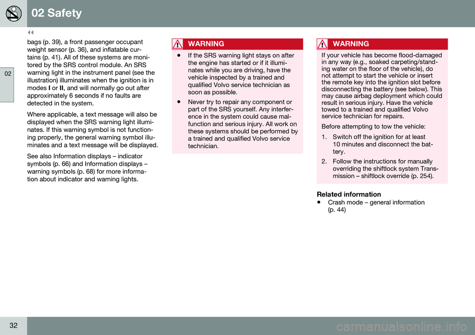
bags (p. 39), a front passenger occupant weight sensor (p. 36), and inflatable cur-tains (p. 41). All of these systems are moni-tored by the SRS control module. An SRSwarning light in the instrument panel (see theillustration) illuminates when the ignition is inmodes I or II, and will normally go out after
approximately 6 seconds if no faults aredetected in the system. Where applicable, a text message will also be displayed when the SRS warning light illumi-nates. If this warning symbol is not function-ing properly, the general warning symbol illu-minates and a text message will be displayed. See also Information displays – indicator symbols (p. 66) and Information displays –warning symbols (p. 68) for more informa-tion about indicator and warning lights.WARNING
• If the SRS warning light stays on after the engine has started or if it illumi-nates while you are driving, have thevehicle inspected by a trained andqualified Volvo service technician assoon as possible.
• Never try to repair any component orpart of the SRS yourself. Any interfer-ence in the system could cause mal-function and serious injury. All work onthese systems should be performed bya trained and qualified Volvo servicetechnician.
WARNING
If your vehicle has become flood-damaged in any way (e.g., soaked carpeting/stand-ing water on the floor of the vehicle), donot attempt to start the vehicle or insertthe remote key into the ignition slot beforedisconnecting the battery (see below). Thismay cause airbag deployment which couldresult in serious injury. Have the vehicletowed to a trained and qualified Volvoservice technician for repairs. Before attempting to tow the vehicle:
1. Switch off the ignition for at least
10 minutes and disconnect the bat- tery.
2. Follow the instructions for manually overriding the shiftlock system Trans-mission – shiftlock override (p. 254).
Related information
• Crash mode – general information (p. 44)
Page 39 of 392
02 Safety
02
}}
37
NOTE
When the ignition is switched on, the OWS indicator light will go on for up to 10 sec-onds while the system performs a self-diagnostic test.
However, if a fault is detected in the system:• The OWS indicator light will stay on
• The SRS warning light (p. 31) will come on and stay on
• The message
Pass. Airbag OFF Service
urgent will be displayed in the informa-
tion display.
WARNING
If a fault in the system is detected and indicated as described, be aware that thepassenger's side front airbag will notdeploy in the event of a collision. In thiscase, the SRS system and OccupantWeight Sensor should be inspected by atrained and qualified Volvo service techni-cian as soon as possible.
WARNING
• Never try to open, remove, or repair any components in the OWS system.This could result in system malfunc-tion. Maintenance or repairs shouldonly be carried out by an a trained andqualified Volvo service technician.
• The front passenger's seat should notbe modified in any way. This couldreduce pressure on the seat cushion,which might interfere with the OWSsystem's function.
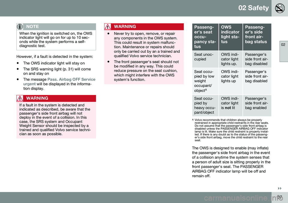
Passeng- er's seatoccu-pancy sta-tusOWS indicatorlight sta-tusPasseng- er's sidefront air-bag status
Seat unoc- cupiedOWS indi- cator lightlights up.Passenger's side front air-bag disabled
Seat occu- pied by lowweightoccupant/ object AOWS indi- cator lightlights upPassenger's side front air-bag disabled
Seat occu- pied byheavy occu-pant/objectOWS indi- cator lightis
not litPassenger's side front air-bag enabled
A
Volvo recommends that children always be properly restrained in appropriate child restraints in the rear seats.Do not assume that the passenger's side front airbag isdisabled unless the PASSENGER AIRBAG OFF indicatorlamp is lit. Make sure the child restraint is properly instal-led. If there is any doubt as to the status of the passeng-er's side front airbag, move the child restraint to the rearseat.
The OWS is designed to enable (may inflate) the passenger's side front airbag in the eventof a collision anytime the system senses thata person of adult size is sitting properly in thefront passenger's seat. The PASSENGERAIRBAG OFF indicator lamp will be off andremain off.
Page 69 of 392
03 Instruments and controls
03
}}
* Option/accessory, for more information, see Introduction.67
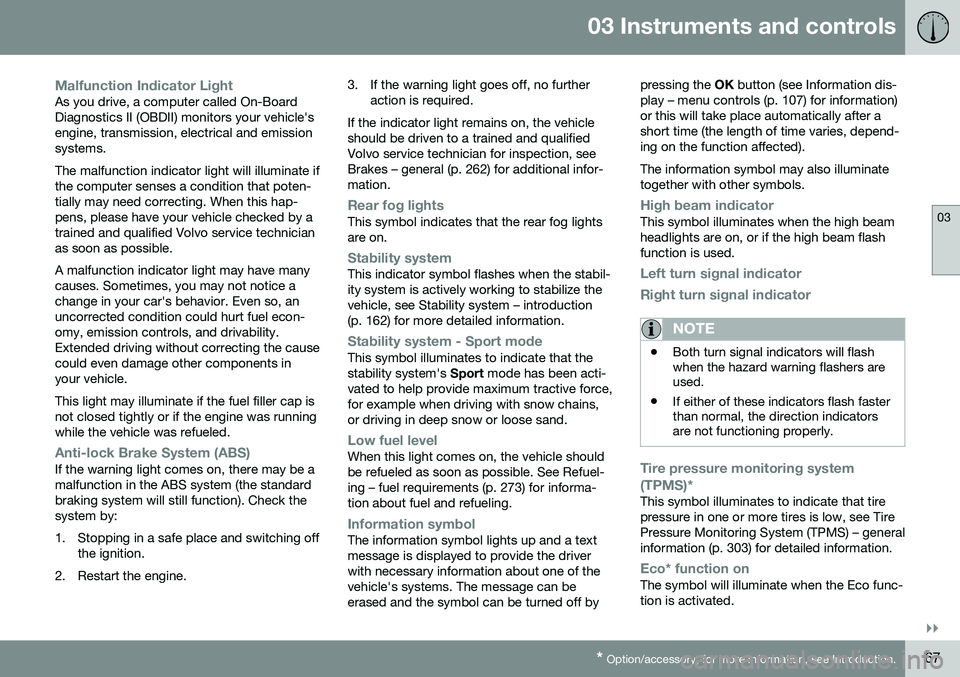
Malfunction Indicator LightAs you drive, a computer called On-Board Diagnostics II (OBDII) monitors your vehicle'sengine, transmission, electrical and emissionsystems. The malfunction indicator light will illuminate if the computer senses a condition that poten-tially may need correcting. When this hap-pens, please have your vehicle checked by atrained and qualified Volvo service technicianas soon as possible. A malfunction indicator light may have many causes. Sometimes, you may not notice achange in your car's behavior. Even so, anuncorrected condition could hurt fuel econ-omy, emission controls, and drivability.Extended driving without correcting the causecould even damage other components inyour vehicle. This light may illuminate if the fuel filler cap is not closed tightly or if the engine was runningwhile the vehicle was refueled.
Anti-lock Brake System (ABS)If the warning light comes on, there may be a malfunction in the ABS system (the standardbraking system will still function). Check thesystem by:
1. Stopping in a safe place and switching off
the ignition.
2. Restart the engine. 3. If the warning light goes off, no further
action is required.
If the indicator light remains on, the vehicle should be driven to a trained and qualifiedVolvo service technician for inspection, seeBrakes – general (p. 262) for additional infor-mation.
Rear fog lightsThis symbol indicates that the rear fog lights are on.
Stability systemThis indicator symbol flashes when the stabil- ity system is actively working to stabilize thevehicle, see Stability system – introduction(p. 162) for more detailed information.
Stability system - Sport modeThis symbol illuminates to indicate that the stability system's Sport mode has been acti-
vated to help provide maximum tractive force,for example when driving with snow chains,or driving in deep snow or loose sand.
Low fuel levelWhen this light comes on, the vehicle should be refueled as soon as possible. See Refuel-ing – fuel requirements (p. 273) for informa-tion about fuel and refueling.
Information symbolThe information symbol lights up and a text message is displayed to provide the driverwith necessary information about one of thevehicle's systems. The message can beerased and the symbol can be turned off by pressing the
OK button (see Information dis-
play – menu controls (p. 107) for information)or this will take place automatically after ashort time (the length of time varies, depend-ing on the function affected). The information symbol may also illuminate together with other symbols.
High beam indicatorThis symbol illuminates when the high beam headlights are on, or if the high beam flashfunction is used.
Left turn signal indicator
Right turn signal indicator
NOTE
• Both turn signal indicators will flash when the hazard warning flashers areused.
• If either of these indicators flash fasterthan normal, the direction indicatorsare not functioning properly.
Tire pressure monitoring system (TPMS)*
This symbol illuminates to indicate that tire pressure in one or more tires is low, see TirePressure Monitoring System (TPMS) – generalinformation (p. 303) for detailed information.
Eco* function onThe symbol will illuminate when the Eco func- tion is activated.
Page 70 of 392
||
03 Instruments and controls
03
68* Option/accessory, for more information, see Introduction.
Start/stop*The symbol illuminates when the engine has auto-stopped.
Related information
• Information displays – introduction (p. 62)
• Information displays – warning symbols (p. 68)
Information displays – warning symbols
The warning lights alert the driver that an important function is activated or that a seri-ous fault has occurred.
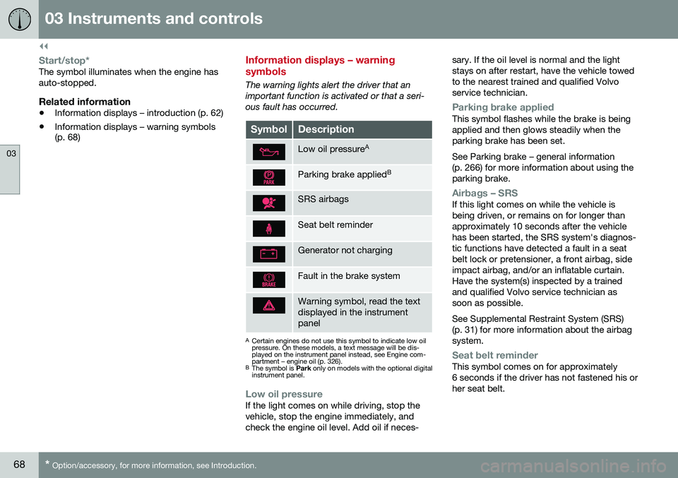
SymbolDescription
Low oil pressure A
Parking brake applied B
SRS airbags
Seat belt reminder
Generator not charging
Fault in the brake system
Warning symbol, read the text displayed in the instrumentpanel
A
Certain engines do not use this symbol to indicate low oil pressure. On these models, a text message will be dis-played on the instrument panel instead, see Engine com-partment – engine oil (p. 326).
B The symbol is Park only on models with the optional digital
instrument panel.
Low oil pressureIf the light comes on while driving, stop the vehicle, stop the engine immediately, andcheck the engine oil level. Add oil if neces- sary. If the oil level is normal and the lightstays on after restart, have the vehicle towedto the nearest trained and qualified Volvoservice technician.
Parking brake appliedThis symbol flashes while the brake is being applied and then glows steadily when theparking brake has been set. See Parking brake – general information (p. 266) for more information about using theparking brake.
Airbags – SRSIf this light comes on while the vehicle is being driven, or remains on for longer thanapproximately 10 seconds after the vehiclehas been started, the SRS system's diagnos-tic functions have detected a fault in a seatbelt lock or pretensioner, a front airbag, sideimpact airbag, and/or an inflatable curtain.Have the system(s) inspected by a trainedand qualified Volvo service technician assoon as possible. See Supplemental Restraint System (SRS) (p. 31) for more information about the airbagsystem.
Seat belt reminderThis symbol comes on for approximately 6 seconds if the driver has not fastened his orher seat belt.
Page 71 of 392
03 Instruments and controls
03
}}
69
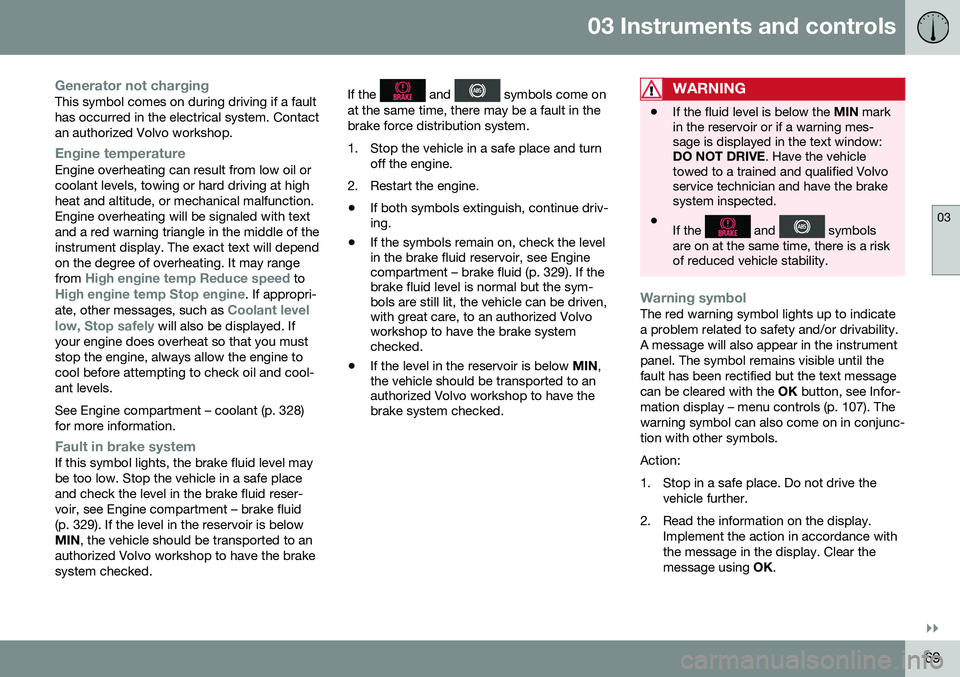
Generator not chargingThis symbol comes on during driving if a fault has occurred in the electrical system. Contactan authorized Volvo workshop.
Engine temperatureEngine overheating can result from low oil or coolant levels, towing or hard driving at highheat and altitude, or mechanical malfunction.Engine overheating will be signaled with textand a red warning triangle in the middle of theinstrument display. The exact text will dependon the degree of overheating. It may range from
High engine temp Reduce speed toHigh engine temp Stop engine. If appropri-
ate, other messages, such as Coolant level
low, Stop safely will also be displayed. If
your engine does overheat so that you must stop the engine, always allow the engine tocool before attempting to check oil and cool-ant levels. See Engine compartment – coolant (p. 328) for more information.
Fault in brake systemIf this symbol lights, the brake fluid level may be too low. Stop the vehicle in a safe placeand check the level in the brake fluid reser-voir, see Engine compartment – brake fluid(p. 329). If the level in the reservoir is belowMIN , the vehicle should be transported to an
authorized Volvo workshop to have the brakesystem checked. If the
and symbols come on
at the same time, there may be a fault in the brake force distribution system.
1. Stop the vehicle in a safe place and turn off the engine.
2. Restart the engine.
• If both symbols extinguish, continue driv- ing.
• If the symbols remain on, check the levelin the brake fluid reservoir, see Enginecompartment – brake fluid (p. 329). If thebrake fluid level is normal but the sym-bols are still lit, the vehicle can be driven,with great care, to an authorized Volvoworkshop to have the brake systemchecked.
• If the level in the reservoir is below
MIN,
the vehicle should be transported to anauthorized Volvo workshop to have thebrake system checked.WARNING
• If the fluid level is below the
MIN mark
in the reservoir or if a warning mes- sage is displayed in the text window:DO NOT DRIVE . Have the vehicle
towed to a trained and qualified Volvoservice technician and have the brakesystem inspected.
• If the
and symbols
are on at the same time, there is a risk of reduced vehicle stability.
Warning symbolThe red warning symbol lights up to indicate a problem related to safety and/or drivability.A message will also appear in the instrumentpanel. The symbol remains visible until thefault has been rectified but the text messagecan be cleared with the OK button, see Infor-
mation display – menu controls (p. 107). Thewarning symbol can also come on in conjunc-tion with other symbols. Action:
1. Stop in a safe place. Do not drive the vehicle further.
2. Read the information on the display. Implement the action in accordance with the message in the display. Clear themessage using OK.
Page 75 of 392
03 Instruments and controls
03
}}
* Option/accessory, for more information, see Introduction.73
Removing the remote keyThe remote key can be removed from the ignition slot by pulling it out.
Related information
• Ignition modes (p. 73)
Ignition modes
The vehicle's ignition has 3 modes:
0, I, and II
that can be used without starting the engine. The following table shows examples of whichfunctions are available in the respectivemodes.
NOTE
To access ignition modes I or II without
starting the engine, the brake pedal must not be depressed.
ModeFunction
0The odometer, clock and tem- perature gauge are illuminated.Power seats* can be adjustedand the infotainment system canbe used for a limited time (to min-imize battery drain, see the Sen-sus Infotainment Supplement).
IThe Moonroof*, power windows, 12-volt sockets in the passengercompartment, navigation sys-tem*, climate system blower,windshield wipers can be used.
IIThe headlights/taillights illumi- nate. Warning/indicator lights illu-minate for 5 seconds. Other sys-tems are activated. However, theheated seats* and heated rearwindow function can only be acti-vated when the engine is running. Mode II should only be used for very short periods to help avoiddraining the battery.
Ignition modes
Ignition mode 0–The vehicle is unlocked.
Page 90 of 392
||
03 Instruments and controls
03
88
NOTE
•The rear fog lights are considerably brighter than the normal taillights andshould be used only when conditionssuch as fog, rain, snow, smoke or dustreduce visibility for other vehicles toless than 500 ft. (150 meters).
• Condensation may form temporarily onthe inside of the lenses of exteriorlights such as headlights, fog lights, ortaillights. This is normal and the lightsare designed to withstand moisture.Normally, condensation will dissipateafter the lights have been on for ashort time.
Related information
•
Lighting panel (p. 82)
Hazard warning flashers
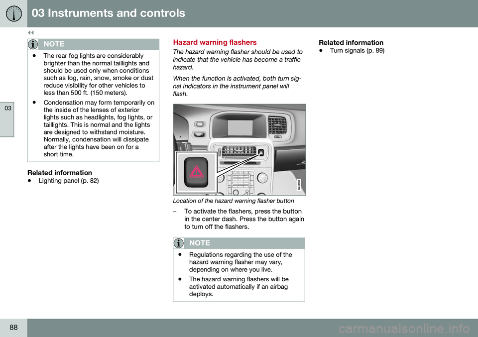
The hazard warning flasher should be used to indicate that the vehicle has become a traffichazard. When the function is activated, both turn sig- nal indicators in the instrument panel willflash.
Location of the hazard warning flasher button
–To activate the flashers, press the button in the center dash. Press the button againto turn off the flashers.
NOTE
•Regulations regarding the use of the hazard warning flasher may vary,depending on where you live.
• The hazard warning flashers will beactivated automatically if an airbagdeploys.
Related information
•
Turn signals (p. 89)
Page 183 of 392
07 Driver support
07
}}
181
Radar sensor
The radar sensor is designed to help detect cars or larger vehicles driving in the samedirection as your vehicle, in the same lane.
The radar sensor and its limitationsIn addition to being used by the AdaptiveCruise Control (ACC), the radar sensor is alsoused by Distance Alert (see Distance Alert –introduction (p. 186)) and Collision Warningwith Full Auto-brake and Pedestrian Detec-tion (see Collision warning – introduction(p. 197)).
WARNING
•If there is visible damage to the front grille or you suspect that the radarsensor may be damaged in any way,contact a trained and qualified Volvoservice technician as soon as possible.The radar sensor may only functionpartially (or not at all) if it is damagedor is not securely fastened in place.
• Accessories or other objects, such asextra headlights, must not be installedin front of the grille.
• Modification of the radar sensor couldmake its use illegal.
The radar sensor's capacity to detect vehi- cles ahead is impeded:
• if the radar sensor is obstructed and can- not detect other vehicles, for example in heavy rain, or if snow or other objects areobscuring the radar sensor.
NOTE
Keep the area in front of the radar sensor clean.
•
if the speed of vehicles ahead is signifi- cantly different from your own speed.
Related information
•Adaptive Cruise Control – introduction(p. 172)
• Collision warning – introduction (p. 197)
• Distance Alert – introduction (p. 186)
Adaptive Cruise Control – limitations
The ACC cannot cover all driving situations and traffic, weather and road conditions.
Situations where ACC may not function optimally
WARNING
• The radar sensor has a limited field of vision. In some situations it may detecta vehicle later than expected or notdetect other vehicles at all.
• If ACC is not functioning properly,cruise control will also be disabled.
Page 194 of 392
07 Driver support
07
192
City Safety – operation
Using City Safety™
NOTE
The City Safety™ function is activated automatically each time the engine hasbeen switched off and restarted.
On and OffIn certain situations, it may be desirable to switch City Safety™ off, such as when drivingin close quarters where leaves, branches, etc.may obscure the hood and windshield. When the engine is running, City Safety™ can be switched off as follows: Press My Car in the center console control
panel and go to
SettingsCar settings
Driver support systemsCity Safety.
Select
Off.
If the engine is switched off, City Safety™ will reactivate when the engine is restarted.
WARNING
The laser sensor emits light when the igni- tion is in mode II or higher, even if City
Safety™ has been switched off.
To switch City Safety™ on again:
• Follow the same procedure as for switch- ing City Safety™ off but select
On.
Related information
•City Safety – introduction (p. 190)
• City Safety – function (p. 191)
• City Safety – limitations (p. 192)
• City Safety – troubleshooting (p. 193)
• City Safety – symbols and messages (p. 195)
• City Safety – Laser sensor (p. 196)
• My Car – introduction (p. 70)
City Safety – limitations
Limitations
WARNING
The laser sensor has certain limitations and its function may be reduced (or it maynot function at all) in conditions such asheavy rain or snowfall, or by dense fog orthick, blowing dust or snow. Condensa-tion, dirt, ice or snow on the windshieldmay also interfere with the sensor’s func-tion.
The sensor used by City Safety™ is designed to detect cars and other larger motor vehiclesahead of your vehicle in both daylight anddarkness. Objects such as warning flags hanging from long objects on the roof or accessories suchas auxiliary lights or protective arches on thefront of the vehicle that are higher than thehood may also impede the sensor’s function. Braking distance to the vehicle ahead increa- ses on slippery road surfaces, which mayreduce City Safety’s capacity to avoid a colli-sion. In situations like this, the stability sys-tem (see Stability system – introduction(p. 162)) will help provide the best possiblebraking capacity and stability. City Safety™ emits a laser beam and meas- ures the way in which the light is reflected.