window VOLVO S60 CROSS COUNTRY 2018 Owner´s Manual
[x] Cancel search | Manufacturer: VOLVO, Model Year: 2018, Model line: S60 CROSS COUNTRY, Model: VOLVO S60 CROSS COUNTRY 2018Pages: 394, PDF Size: 9.41 MB
Page 5 of 394

3
Active Bending Lights (ABL)*
86
Auxiliary lights *
87
Instrument and "theater" lighting 88
Parking lights 88
Rear fog lights 89
Hazard warning flashers 89
Turn signals 90
Front interior lighting 91
Rear interior lighting 92
Home safe lighting 92
Approach lighting 92
Windshield wipers 93
Rain sensor *
94
Windshield washer 94
Tailgate wiper/washer 95
Power windows 96
Sun shades 97
Power door mirrors 97
Power door mirrors – automatic tilt- ing/retraction 98
Heated windshield *, rear window and
door mirror defrosters 99
Interior rearview mirror 100
Digital compass *
100
Power moonroof – introduction 101
Power moonroof – operation102
HomeLink ®
Wireless Control Sys-
tem * – introduction 103
HomeLink ®
Wireless Control Sys-
tem * – programming 104
Volvo Sensus 107
Information display – menu controls 108
Information display – menu overview 108
Information display – messages 109
Trip computer – introduction 110
Trip computer – functions, analog instrument panel 111
Trip computer – functions, digitalinstrument panel 114
Trip computer – Supplementaryinformation 116
Trip computer – Trip statistics 117
CLIMATE
Climate – general information120
Climate – sensors 121
Air quality 121
Interior Air Quality System (IAQS) *
122
Climate – menu settings 123
Air distribution – general 123
Electronic climate control (ECC) 125
Heated seats 126
Temperature and blower control 127
Automatic climate control 127
Air conditioning 128
Max. defroster and electrically heated windshield * 128
Air distribution – function 129
Air distribution – recirculation 130
Air distribution – table 131
Page 37 of 394

SAFETY
}}
35
NOTE
•Deployment of front airbags occurs only one time during an accident. In a collisionwhere deployment occurs, the airbagsand seat belt pretensioners activate.Some noise occurs and a small amountof powder is released. The release of thepowder may appear as smoke-like matter.This is a normal characteristic and doesnot indicate fire.
• Volvo's front airbags use special sensorsthat are integrated with the front seatbuckles. The point at which the airbagdeploys is determined by whether or notthe seat belt is being used, as well as theseverity of the collision.
• Collisions can occur where only one ofthe airbags deploys. If the impact is lesssevere, but severe enough to present aclear injury risk, the airbags are triggeredat partial capacity. If the impact is moresevere, the airbags are triggered at fullcapacity.
Airbag decals
Airbag decal on the outside of both sun visors
Passenger's side airbag decal
WARNING
• Children must never be allowed in the front passenger's seat.
• Occupants in the front passenger's seatmust never sit on the edge of the seat, sitleaning toward the instrument panel orotherwise sit out of position.
• The occupant's back must be as uprightas comfort allows and be against the seatback with the seat belt properly fastened.
• Feet must be on the floor, e.g., not on thedash, seat or out of the window.
Page 43 of 394

SAFETY
}}
41
Related information
•Supplemental Restraint System (SRS) (p. 31)
• Front airbags (p. 33)
• Inflatable Curtain (IC) (p. 41)
Inflatable Curtain (IC)
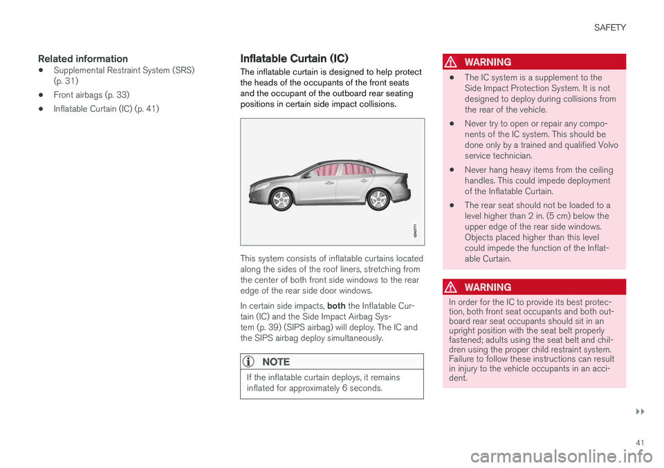
The inflatable curtain is designed to help protect the heads of the occupants of the front seatsand the occupant of the outboard rear seatingpositions in certain side impact collisions.
This system consists of inflatable curtains located along the sides of the roof liners, stretching fromthe center of both front side windows to the rearedge of the rear side door windows. In certain side impacts, both the Inflatable Cur-
tain (IC) and the Side Impact Airbag Sys- tem (p. 39) (SIPS airbag) will deploy. The IC andthe SIPS airbag deploy simultaneously.
NOTE
If the inflatable curtain deploys, it remains inflated for approximately 6 seconds.
WARNING
• The IC system is a supplement to the Side Impact Protection System. It is notdesigned to deploy during collisions fromthe rear of the vehicle.
• Never try to open or repair any compo-nents of the IC system. This should bedone only by a trained and qualified Volvoservice technician.
• Never hang heavy items from the ceilinghandles. This could impede deploymentof the Inflatable Curtain.
• The rear seat should not be loaded to alevel higher than 2 in. (5 cm) below theupper edge of the rear side windows.Objects placed higher than this levelcould impede the function of the Inflat-able Curtain.
WARNING
In order for the IC to provide its best protec- tion, both front seat occupants and both out-board rear seat occupants should sit in anupright position with the seat belt properlyfastened; adults using the seat belt and chil-dren using the proper child restraint system.Failure to follow these instructions can resultin injury to the vehicle occupants in an acci-dent.
Page 64 of 394

||
INSTRUMENTS AND CONTROLS
* Option/accessory.
62
Function See
Controls for menus and messages, turn signals,high/low beams, tripcomputer(p. 71),(p. 90),(p. 83),(p. 110)
Paddles for manually shifting gears
*(p. 257)
Cruise control (p. 172)
Horn, airbag (p. 82),
(p. 33)
Main instrument panel (p. 63)
Infotainment system/ Bluetooth hands-freecontrolsSensus Info-tainment sup-plement
START/STOP ENGINE button
(p. 73)
Ignition slot (p. 73)
Display for infotainment system functions andmenus(p. 108), Sen-sus Infotain-ment supple-ment
Door handle -
Function
See
In-door control panels (power windows, mir-rors, central locking but-ton)(p. 96),(p. 97),(p. 158)
Hazard warning flashers (p. 89)
Controls for the info- tainment system andmenus
(p. 71),(p. 125), Sen-sus Infotain-ment supple-ment
Climate system controls (p. 125)
Gear selector (p. 255)
Not in use -
Wipers and washers (p. 93),
(p. 94)
Steering wheel adjust- ment(p. 82)
Hood opening control (p. 327)
Parking brake (p. 271)
Function
See
Power seat* adjustment
controls (p. 76)
Lighting panel, buttons for opening fuel fillerdoor and unlocking andopening the trunk(p. 83),(p. 280),(p. 160)
Related information
•
Information displays – ambient temperature sensor (p. 72)
• Information displays – trip odometer andclock (p. 73)
Page 72 of 394

||
INSTRUMENTS AND CONTROLS
70
Engine temperature
Engine overheating can result from low oil or coolant levels, towing or hard driving at high heatand altitude, or mechanical malfunction. Engineoverheating will be signaled with text and a redwarning triangle in the middle of the instrumentdisplay. The exact text will depend on the degree of overheating. It may range from
High engine
temp Reduce speed to High engine temp
Stop engine. If appropriate, other messages,
such as Coolant level low, Stop safely will
also be displayed. If your engine does overheat so that you must stop the engine, always allowthe engine to cool before attempting to check oiland coolant levels. See Engine compartment – coolant (p. 332) for more information.
Fault in brake system
If this symbol lights, the brake fluid level may be too low. Stop the vehicle in a safe place andcheck the level in the brake fluid reservoir, seeEngine compartment – brake fluid (p. 333). If the level in the reservoir is below MIN, the vehicle
should be transported to an authorized Volvo workshop to have the brake system checked. If the
and symbols come on at
the same time, there may be a fault in the brake force distribution system. 1. Stop the vehicle in a safe place and turn off
the engine.
2. Restart the engine.
• If both symbols extinguish, continue driving.
• If the symbols remain on, check the level inthe brake fluid reservoir, see Engine com-partment – brake fluid (p. 333). If the brakefluid level is normal but the symbols are stilllit, the vehicle can be driven, with great care,to an authorized Volvo workshop to have thebrake system checked.
• If the level in the reservoir is below
MIN, the
vehicle should be transported to an author-ized Volvo workshop to have the brake sys-tem checked.
WARNING
• If the fluid level is below the
MIN mark in
the reservoir or if a warning message is displayed in the text window: DO NOT
DRIVE . Have the vehicle towed to a
trained and qualified Volvo service techni- cian and have the brake system inspec-ted.
• If the
and symbols are
on at the same time, there is a risk of reduced vehicle stability.
Warning symbol
The red warning symbol lights up to indicate a problem related to safety and/or drivability. Amessage will also appear in the instrument panel.The symbol remains visible until the fault hasbeen rectified but the text message can be cleared with the OK button, see Information dis-
play – menu controls (p. 108). The warning sym- bol can also come on in conjunction with othersymbols. Action:
1. Stop in a safe place. Do not drive the vehicle further.
2. Read the information on the display. Imple- ment the action in accordance with the mes- sage in the display. Clear the message using OK.
Page 76 of 394

||
INSTRUMENTS AND CONTROLS
* Option/accessory.
74
CAUTION
Foreign objects in the ignition slot can impair function or cause damage.
Removing the remote keyThe remote key can be removed from the ignition slot by pulling it out.
Related information
• Ignition modes (p. 74)
Ignition modes
The vehicle's ignition has 3 modes: 0, I, and II
that can be used without starting the engine. The following table shows examples of whichfunctions are available in the respective modes.
NOTE
To access ignition modes I or II without star-
ting the engine, the brake pedal must not be
depressed.
Mode Function
0 The odometer, clock and temperature gauge are illuminated. Power seats
*
can be adjusted and the infotainment system can be used for a limited time(to minimize battery drain, see theSensus Infotainment Supplement).
I The Moonroof *, power windows,12-
volt sockets in the passenger com- partment, navigation system *, climate
system blower, windshield wipers can be used.
II The headlights/taillights illuminate.Warning/indicator lights illuminate for5 seconds. Other systems are acti- vated. However, the heated seats
* and
heated rear window function can only be activated when the engine is run- ning. Mode II should only be used
for very short periods to help avoid draining the battery.
Ignition modes
Ignition mode 0
–The vehicle is unlocked.
Page 95 of 394

INSTRUMENTS AND CONTROLS
* Option/accessory.93
Windshield wipers Move the lever toward the steering wheel to start the windshield and headlight washers. After thelever is released the wipers make several extrasweeps.
Windshield wipers and washers
Rain sensor* on/off
Thumb wheel sensitivity/frequency
CAUTION
• Use ample washer fluid when washing the windshield. The windshield should bethoroughly wet when the wipers are inoperation.
• Before using the wipers, ice and snowshould be removed from the windshield/rear window. Be sure the wiper bladesare not frozen in place.
Windshield wipers off
Move the lever to position
0 to switch
off the windshield wipers.
Single sweep
Move the lever upward from position 0
to sweep the windshield one stroke at a time for as long as the lever is held
up.
Intermittent wiping
With the lever in this position, you can set the wiper interval by twisting thethumb wheel upward to increase wiper
speed or downward to decrease the speed.
Continuous wiping
The wipers operate at normal speed.
The wipers operate at high speed.
Windshield wiper service position
The windshield wipers must be in the service position before the wiper blades can be cleanedor replaced. See Wiper blades – service position(p. 342) for additional information.
Related information
• Engine compartment – washer fluid (p. 344)
Page 98 of 394

INSTRUMENTS AND CONTROLS
96
Power windows
All power windows can be operated using the control panel in the driver's door. The controlpanels in the other doors only operate the win-dow in the respective doors.
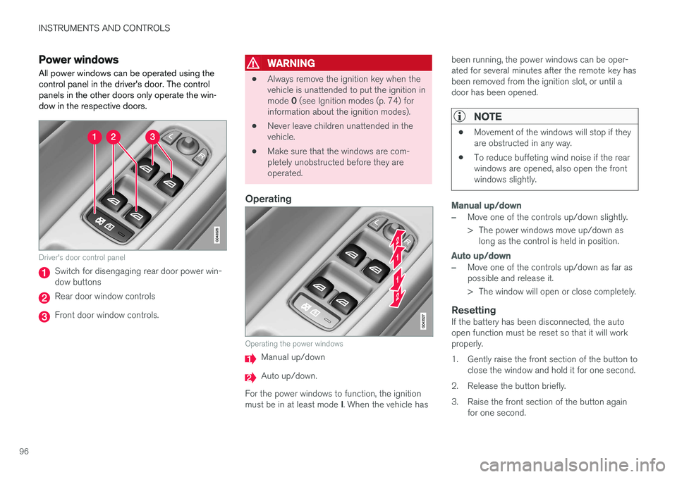
Driver's door control panel
Switch for disengaging rear door power win- dow buttons
Rear door window controls
Front door window controls.
WARNING
• Always remove the ignition key when the vehicle is unattended to put the ignition in mode
0 (see Ignition modes (p. 74) for
information about the ignition modes).
• Never leave children unattended in the vehicle.
• Make sure that the windows are com-pletely unobstructed before they areoperated.
Operating
Operating the power windows
Manual up/down
Auto up/down.
For the power windows to function, the ignition must be in at least mode I. When the vehicle has been running, the power windows can be oper- ated for several minutes after the remote key hasbeen removed from the ignition slot, or until adoor has been opened.
NOTE
•
Movement of the windows will stop if they are obstructed in any way.
• To reduce buffeting wind noise if the rearwindows are opened, also open the frontwindows slightly.
Manual up/down
–Move one of the controls up/down slightly.
> The power windows move up/down as
long as the control is held in position.
Auto up/down
–Move one of the controls up/down as far as possible and release it.
> The window will open or close completely.
ResettingIf the battery has been disconnected, the auto open function must be reset so that it will workproperly.
1. Gently raise the front section of the button to close the window and hold it for one second.
2. Release the button briefly.
3. Raise the front section of the button again for one second.
Page 100 of 394

||
INSTRUMENTS AND CONTROLS
* Option/accessory.
98
Tilting the door mirrors when parking *
The door mirrors can be tilted down to help give the driver a better view along the sides of thevehicle, for example when parallel parking. To activate this function, select reverse gear and press the L or R mirror control button to tilt the
mirror down. The function can be activated/deactivated in MY CAR under
SettingsCar settings
Side mirror settingsTilt left mirror or Tilt
right mirror. See My Car – introduction (p. 71)
for a description of the menu system. The door mirror will reset to its normal position:
• after 10 seconds when reverse is disen- gaged and the car remains stopped.
• immediately when reverse is disengaged andthe vehicle's forward speed exceeds approxi-mately 6 mph (10 km/h).
• immediately if you press the corresponding
L
or R button again.
• when the engine is turned off.
• when the side mirrors are folded in.
NOTE
Only one mirror can be tilted down at a time.
Home safe and approach lightingThe light on the door mirrors comes on when approach lighting or home safe lighting isselected, see Approach lighting (p. 92) andHome safe lighting (p. 92).
Related information
•
Interior rearview mirror (p. 100)
• Heated windshield
*, rear window and door
mirror defrosters (p. 99)
• Power door mirrors – automatic tilting/retraction (p. 98)
Power door mirrors – automatic tilting/retraction
The control on the driver's door is used to adjust the position of the door mirrors.
Automatically tilting the door mirrors
when parking
The door mirrors can tilt down automatically to help give the driver a better view along the sidesof the vehicle, for example when parallel parking.When the transmission is no longer in reverse,the mirrors will automatically return to their origi-nal position. This function can be activated/deactivated in MY
CAR under
SettingsCar settingsSide
mirror settings
In reverse gear tilt left
mirror or In reverse gear tilt right mirror. See
My Car – introduction (p. 71) for information about the MY CAR menu system.
Automatic retraction when lockingWhen the vehicle is locked/unlocked with the remote key the door mirrors are automaticallyretracted/extended. The function can be activated/deactivated in MY CAR under
SettingsCar settings
Side mirror settingsRetract side mirrors
when locking. See My Car – introduction (p. 71)
for a description of the menu system.
Page 101 of 394

INSTRUMENTS AND CONTROLS
* Option/accessory.99
Resetting to neutralMirrors that have been moved out of position by an external force must be electrically reset to theneutral position for electric retracting/extendingto work. •Retract the mirrors with the
L and R buttons.
• Fold them out again with the
L and R but-
tons.
The mirrors are now reset in neutral position.
Related information
• Interior rearview mirror (p. 100)
• Heated windshield
*, rear window and door
mirror defrosters (p. 99)
Heated windshield *, rear window
and door mirror defrosters
The heating function is used to defrost/de-ice the windshield and/or the rear window and doormirrors.
Heated windshield
Heated rear window and door mirrors
Press button (1) to defrost/de-ice the windshield and/or button (2) to defrost the rear window anddoor mirrors. The indicator lights in the respectivebuttons indicate that the function is active. Switchthe function off when then windshield/rear win-dow/mirrors have cleared to help avoid batterydrain. The heating function will also switch offautomatically after a certain amount of time. The rear window is then defogged/de-iced (the function will switch on and off automatically until the ignition is switched off) if the ambient tem-perature remains below 45 °F (7 °C). Auto-defrosting for the rear window and door mirrors (if the vehicle is started when the ambienttemperature is below 45 °F (7 °C) can be selected in MY CAR under
SettingsClimate
settings
Automatic rear defroster.
If the Engine Remote Start (ERS) * function is
used, the electrically heated windshield function will be activated automatically at temperaturesbelow approx. 40 °F (+5 °C) if auto-defrostinghas been selected in the MY CAR menu. See My Car – introduction (p. 71) for a descrip- tion of the menu system.