wheel VOLVO S60 INSCRIPTION 2016 Owner´s Manual
[x] Cancel search | Manufacturer: VOLVO, Model Year: 2016, Model line: S60 INSCRIPTION, Model: VOLVO S60 INSCRIPTION 2016Pages: 344, PDF Size: 7.24 MB
Page 5 of 344
Contents
* Option/accessory, for more information, see Introduction.3
03
03 Instruments and controls
Instrument overview ................................. 58
Information displays – introduction........... 58
Eco Guide* and Power Meter*.................. 61
Information displays – indicator symbols. 62
Information displays – warning symbols... 64
My Car – introduction............................... 66Information displays – ambient tempera-
ture sensor................................................ 67 Information displays – trip odometer and
clock......................................................... 67
Inserting/removing remote key................. 68
Ignition modes.......................................... 69
Front seats................................................ 70
Front seats – folding backrest*................. 70
Front seats – power seat.......................... 71Key memory – power driver's seat* and
door mirrors.............................................. 72
Rear seats – head restraints..................... 74
Rear seats – folding backrest................... 74
Steering wheel.......................................... 75
Electrically heated* steering wheel........... 75
Lighting panel........................................... 76
High/low beam headlights........................ 77
Active high beams (AHB)*......................... 77
03
Tunnel detection (models with the rain
sensor* only)............................................. 78
Active Bending Lights (ABL)*.................... 79
Auxiliary lights*.......................................... 79
Instrument and "theater" lighting.............. 80
Parking lights............................................ 80
Rear fog lights........................................... 80
Hazard warning flashers........................... 81
Turn signals............................................... 81
Front interior lighting................................. 82
Rear interior lighting.................................. 83
Home safe lighting.................................... 83
Approach lighting...................................... 83
Windshield wipers..................................... 84
Rain sensor*.............................................. 84
Windshield washer.................................... 85
Tailgate wiper/washer............................... 86
Power windows......................................... 86
Power door mirrors................................... 87Power door mirrors – automatic tilting/
retraction................................................... 88 Heated windshield*, rear window and
door mirror defrosters............................... 89
Interior rearview mirror.............................. 90
03
Digital compass*....................................... 90 HomeLink ®
Wireless Control System* –
introduction............................................... 91HomeLink ®
Wireless Control System* –
programming............................................. 92
Volvo Sensus............................................ 95
Information display – menu controls......... 96
Information display – menu overview....... 96
Information display – messages............... 97
Trip computer – introduction ................... 98Trip computer – functions, analog instru-
ment panel................................................ 99 Trip computer – functions, digital instru-
ment panel.............................................. 102 Trip computer – Supplementary informa-
tion.......................................................... 104
Trip computer – Trip statistics................ 105
Page 8 of 344
Contents
6* Option/accessory, for more information, see Introduction.
07
Collision warning* – limitations............... 181
The camera’s limitations......................... 183
Collision warning – troubleshooting........ 184Collision warning – symbols and mes-
sages....................................................... 186
Driver Alert System................................. 188
Driver Alert Control (DAC) – introduction 188
Driver Alert Control (DAC) – operation.... 189
Driver Alert Control (DAC) – function...... 189
Driver Alert Control (DAC) – limitations... 190Driver Alert Control (DAC) – symbols and
messages................................................ 191 Lane Departure Warning (LDW) – intro-
duction.................................................... 193 Lane Departure Warning (LDW) – opera-
tion.......................................................... 193 Lane Departure Warning (LDW) - limita-
tions........................................................ 195 Lane Departure Warning (LDW) – sym-
bols and messages................................. 196
Park assist – introduction....................... 198
Park assist – function.............................. 198
Park assist – operation........................... 200
Park assist – limitations.......................... 200
Park assist – troubleshooting.................. 201
07
Rear Park Assist Camera (PAC) – intro-
duction.................................................... 201 Rear Park Assist Camera (PAC) – func-
tion.......................................................... 202 Rear Park Assist Camera (PAC) – opera-
tion.......................................................... 202 Rear Park Assist Camera (PAC) – guiding
and marker lines...................................... 203 Rear Park Assist Camera (PAC) – limita-
tions........................................................ 204
BLIS* – introduction................................ 204
BLIS* – function...................................... 205
BLIS* – operation.................................... 206
BLIS* – Cross Traffic Alert (CTA)............. 206
BLIS* – limitations................................... 208
BLIS* – messages................................... 209
08
08 Starting and driving
Starting the engine.................................. 211
Switching off the engine......................... 213Engine Remote Start (ERS)* – introduc-
tion.......................................................... 213 Engine Remote Start (ERS)* – starting the
engine..................................................... 214 Engine Remote Start (ERS)* – switching
off the engine.......................................... 214
Jump starting.......................................... 215
Transmission – general information........ 216
Transmission – positions........................ 216
Transmission – Geartronic...................... 218
Transmission – shiftlock override........... 220
Start/Stop – Hill Start Assist (HSA)......... 221
Start/Stop – introduction........................ 221
Start/Stop – function............................... 221
Start/Stop – Auto-stop exceptions......... 222
Start/Stop – Auto-start exceptions......... 223
Start/Stop – settings............................... 224
Start/Stop – symbols and messages...... 225
ECO*....................................................... 226
All Wheel Drive (AWD)............................. 228
Brakes – general..................................... 228
Brakes – symbols ................................... 230
Page 9 of 344
Contents
* Option/accessory, for more information, see Introduction.7
08
Anti-lock braking system (ABS).............. 230
Brake lights............................................. 231
Emergency Brake Assistance (EBA)....... 231
Parking brake – general information....... 232
Parking brake – applying........................ 232
Parking brake – releasing........................ 233
Parking brake – symbols and messages 235
Driving through water.............................. 236
Engine and cooling system..................... 237
Conserving electrical current.................. 237
Before a long distance trip...................... 237
Driving in cold weather........................... 238
Refueling – fuel requirements................. 239
Refueling – octane rating........................ 240Refueling – opening/closing fuel filler
door......................................................... 241
Refueling – opening/closing fuel cap...... 242
Emission controls.................................... 242
Economical driving.................................. 243
Towing a trailer....................................... 243
Trailer Stability Assist (TSA).................... 245
Towing the vehicle.................................. 245
Towing eyelet.......................................... 246
Towing by tow truck............................... 247
09
09 Wheels and tires
Tires – general information...................... 249
Tires – storage and age.......................... 250
Tires – tread wear indicator.................... 251
Tires – tire economy................................ 251
Changing a wheel – direction of rotation 252
Changing a wheel – removing wheel...... 252
Changing a wheel – spare wheel............ 254Changing a wheel – accessing the spare
wheel....................................................... 254
Changing a wheel – installing a wheel.... 255
Tire inflation – general information.......... 255
Tire inflation – checking pressure........... 256
Tire specifications................................... 257
Tire inflation – pressure table.................. 260
Loading specifications............................ 261
Loading specifications – load limit.......... 261
Tire specifications – terminology............ 262Tire specifications – Uniform Tire Quality
Grading................................................... 263
Snow chains............................................ 264
Snow tires/studded tires......................... 265
Tire pressure monitoring - introduction.. 265Tire Pressure Monitoring System (TPMS)
– general information.............................. 266
09
Tire Pressure Monitoring System (TPMS)
– changing wheels.................................. 267 Tire Pressure Monitoring System (TPMS)
– recalibrating......................................... 268 Tire Pressure Monitoring System (TPMS)
– activating/deactivating......................... 268 Tire Pressure Monitoring System (TPMS)
– messages............................................. 269
Tire Monitor - introduction...................... 270
Calibrating Tire Monitor.......................... 270
Tire Monitor status information............... 271
Tire Monitor – messages......................... 272
Self-supporting run flat tires (SST).......... 273Tire sealing system* – general informa-
tion.......................................................... 273
Tire sealing system* – overview.............. 275
Tire sealing system* – sealing hole......... 276Tire sealing system – checking inflation
pressure.................................................. 278
Tire sealing system* – inflating tires........ 278Tire sealing system* – sealing compound
container................................................. 279
Page 13 of 344
01 Introduction
01
}}
11
On-board owner's manual
The owner's manual can be displayed on the center console screen and you can carry outsearches for the information that you require. To open the owner's manual, press the MY
CAR button on the center console, press OK/
MENU and select
Owner's manual.
For basic information, see "Infotainment - operating the system." The following sectionsalso provide more detailed information.
The on-board owner's manual start page
There are four ways of finding information articles in the on-board owner's manual:
•
Searching: search for an article.
•
Categories: All of the articles are sorted
by category.
•
Favorites: Quick access to frequently
read articles. •
Quick Guide: A selection of articles cov-
ering commonly used functions.
Select the symbol in the lower right-hand cor- ner for additional information about the on-board owner's manual.
NOTE
• The on-board owner's manual cannot be accessed while the vehicle is mov-ing.
• Specifications regarding your vehicleare not found in the on-board informa-tion. This information is listed in theprinted owner's manual.
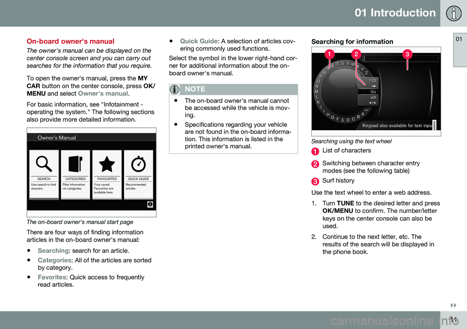
Searching for information
Searching using the text wheel
List of characters
Switching between character entry modes (see the following table)
Surf history
Use the text wheel to enter a web address.
1. Turn TUNE to the desired letter and press
OK/MENU to confirm. The number/letter
keys on the center console can also be used.
2. Continue to the next letter, etc. The results of the search will be displayed inthe phone book.
Page 14 of 344
||
01 Introduction
01
12
3. To switch from letter entry mode to theentry mode for numbers or special char- acters, or to go view surf history, turnTUNE to one of the selections (see the
explanation in the following table) in thelist for switching character entry mode (2)and press OK/MENU .
123/A
BCToggle between letters and num- bers by pressing OK/MENU.
=>This leads to surf history. Turn TUNE to select a web address
and press OK/MENU to go to the
website.
GoGo to the website by pressing OK/MENU .
a|AToggle between upper and lower case letters by pressing OK/
MENU .
| | }Switch from the text wheel to theAddress: field. Use TUNE to
move the cursor and erase char- acters by pressing EXIT. Press
OK/MENU to return to the text
wheel. The number/letter keys on the center console can also be used to edit the
Address: field.
Press EXIT briefly to erase a single character.
Press and hold EXIT to erase all characters.
Pressing a number key on the center console while the text wheel is displayed (see the pre-vious illustration) will display a list of charac-ters. Press the desired key repeatedly toenter the desired letter and continue to thenext letter, etc. To enter a number, press and hold the but- ton.
CategoriesThe articles in the on-board owner's manualare divided into main categories and sub-cat-egories. The same article may be listed inseveral applicable categories to help makesearches easier. Turn TUNE to navigate in the category struc-
ture and press OK/MENU to open a category
(indicated by the
symbol) or an article
(indicated by the
symbol). Press EXIT to
return to the previous view.
FavoritesArticles that have been marked as favorites can be found here. For information aboutmarking an article as a favorite, see "Navigat-ing in an article" below. Turn TUNE to navigate in the list of favorites
and press OK/MENU to open an article.
Press EXIT to return to the previous view.
Quick GuideThis is a selection of articles that will help you become familiar with some of the vehicle'smost common functions. These articles canalso be found in their respective categoriesbut are listed here for quick access. Turn TUNE to navigate in the Quick Guide
and press OK/MENU to open an article.
Press EXIT to return to the previous view.
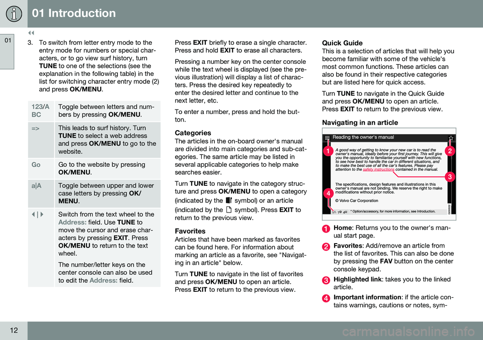
Navigating in an article
Home : Returns you to the owner's man-
ual start page.
Favorites : Add/remove an article from
the list of favorites. This can also be done by pressing the FAV button on the center
console keypad.
Highlighted link : takes you to the linked
article.
Important information : if the article con-
tains warnings, cautions or notes, sym-
Page 32 of 344
02 Safety
02
30
Seat belt reminder
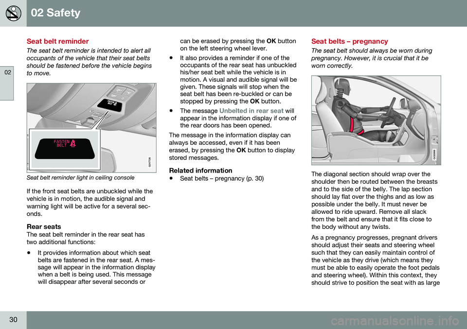
The seat belt reminder is intended to alert all occupants of the vehicle that their seat beltsshould be fastened before the vehicle beginsto move.
G017726
Seat belt reminder light in ceiling consoleIf the front seat belts are unbuckled while the vehicle is in motion, the audible signal andwarning light will be active for a several sec-onds.
Rear seatsThe seat belt reminder in the rear seat hastwo additional functions: • It provides information about which seat belts are fastened in the rear seat. A mes-sage will appear in the information displaywhen a belt is being used. This messagewill disappear after several seconds or can be erased by pressing the
OK button
on the left steering wheel lever.
• It also provides a reminder if one of theoccupants of the rear seat has unbuckledhis/her seat belt while the vehicle is inmotion. A visual and audible signal will begiven. These signals will stop when theseat belt has been re-buckled or can bestopped by pressing the
OK button.
• The message
Unbelted in rear seat will
appear in the information display if one of the rear doors has been opened.
The message in the information display can always be accessed, even if it has beenerased, by pressing the OK button to display
stored messages.
Related information
• Seat belts – pregnancy (p. 30)
Seat belts – pregnancy
The seat belt should always be worn during pregnancy. However, it is crucial that it beworn correctly.
G020998
The diagonal section should wrap over the shoulder then be routed between the breastsand to the side of the belly. The lap sectionshould lay flat over the thighs and as low aspossible under the belly. It must never beallowed to ride upward. Remove all slackfrom the belt and ensure that it fits close tothe body without any twists. As a pregnancy progresses, pregnant drivers should adjust their seats and steering wheelsuch that they can easily maintain control ofthe vehicle as they drive (which means theymust be able to easily operate the foot pedalsand steering wheel). Within this context, theyshould strive to position the seat with as large
Page 33 of 344
02 Safety
02
}}
* Option/accessory, for more information, see Introduction.31
a distance as possible between their belly and the steering wheel.
Related information
•
Seat belts – buckling/unbuckling (p. 29)
• Seat belt reminder (p. 30)
• Child restraints (p. 47)
Supplemental Restraint System (SRS)
As an enhancement to the three-point seat belts (p. 28), your Volvo is equipped with aSupplemental Restraint System (SRS).
Models with an analog instrument panel
Models with an digital instrument panel*
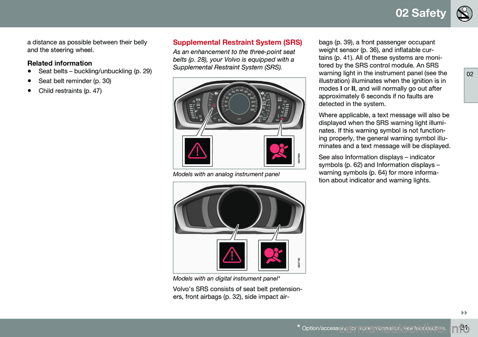
Volvo's SRS consists of seat belt pretension- ers, front airbags (p. 32), side impact air- bags (p. 39), a front passenger occupantweight sensor (p. 36), and inflatable cur-tains (p. 41). All of these systems are moni-tored by the SRS control module. An SRSwarning light in the instrument panel (see theillustration) illuminates when the ignition is inmodes
I or II, and will normally go out after
approximately 6 seconds if no faults aredetected in the system. Where applicable, a text message will also be displayed when the SRS warning light illumi-nates. If this warning symbol is not function-ing properly, the general warning symbol illu-minates and a text message will be displayed. See also Information displays – indicator symbols (p. 62) and Information displays –warning symbols (p. 64) for more informa-tion about indicator and warning lights.
Page 35 of 344
02 Safety
02
}}
33
The location of the front airbags is indicated by
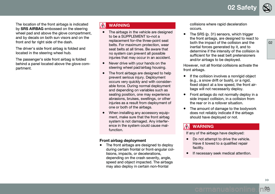
SRS AIRBAG embossed on the steering
wheel pad and above the glove compartment,and by decals on both sun visors and on thefront and far right side of the dash. The driver's side front airbag is folded and located in the steering wheel hub. The passenger's side front airbag is folded behind a panel located above the glove com-partment.
WARNING
• The airbags in the vehicle are designed to be a SUPPLEMENT to–not areplacement for–the three-point seatbelts. For maximum protection, wearseat belts at all times. Be aware thatno system can prevent all possibleinjuries that may occur in an accident.
• Never drive with your hands on thesteering wheel pad/airbag housing.
• The front airbags are designed to helpprevent serious injury. Deploymentoccurs very quickly and with consider-able force. During normal deploymentand depending on variables such asseating position, one may experienceabrasions, bruises, swellings, or otherinjuries as a result from deployment ofone or both of the airbags.
• When installing any accessory equip-ment, make sure that the front airbagsystem is not damaged. Any interfer-ence in the system could cause mal-function.
Front airbag deployment
•
The front airbags are designed to deploy during certain frontal or front-angular col-lisions, impacts, or decelerations,depending on the crash severity, angle,speed and object impacted. The airbagsmay also deploy in certain non-frontal collisions where rapid decelerationoccurs.
• The SRS (p. 31) sensors, which triggerthe front airbags, are designed to react toboth the impact of the collision and theinertial forces generated by it, and todetermine if the intensity of the collision issufficient for the seat belt pretensionersand/or airbags to be deployed.
However, not all frontal collisions activate the front airbags.
• If the collision involves a nonrigid object (e.g., a snow drift or bush), or a rigid,fixed object at a low speed, the front air-bags will not necessarily deploy.
• Front airbags do not normally deploy in aside impact collision, in a collision fromthe rear or in a rollover situation.
• The amount of damage to the bodyworkdoes not reliably indicate if the airbagsshould have deployed or not.
WARNING
If any of the airbags have deployed:
• Do not attempt to drive the vehicle. Have it towed to a qualified repairfacility.
• If necessary seek medical attentIon.
Page 37 of 344
02 Safety
02
35
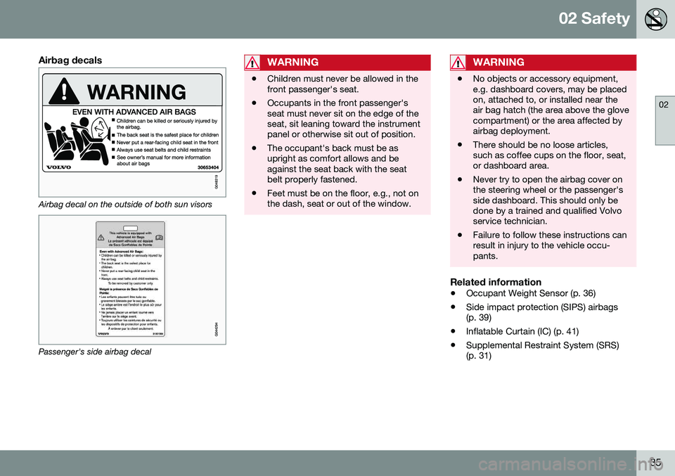
Airbag decals
Airbag decal on the outside of both sun visors
Passenger's side airbag decal
WARNING
•Children must never be allowed in the front passenger's seat.
• Occupants in the front passenger'sseat must never sit on the edge of theseat, sit leaning toward the instrumentpanel or otherwise sit out of position.
• The occupant's back must be asupright as comfort allows and beagainst the seat back with the seatbelt properly fastened.
• Feet must be on the floor, e.g., not onthe dash, seat or out of the window.
WARNING
•
No objects or accessory equipment, e.g. dashboard covers, may be placedon, attached to, or installed near theair bag hatch (the area above the glovecompartment) or the area affected byairbag deployment.
• There should be no loose articles,such as coffee cups on the floor, seat,or dashboard area.
• Never try to open the airbag cover onthe steering wheel or the passenger'sside dashboard. This should only bedone by a trained and qualified Volvoservice technician.
• Failure to follow these instructions canresult in injury to the vehicle occu-pants.
Related information
•
Occupant Weight Sensor (p. 36)
• Side impact protection (SIPS) airbags (p. 39)
• Inflatable Curtain (IC) (p. 41)
• Supplemental Restraint System (SRS)(p. 31)
Page 61 of 344
03 Instruments and controls
03
}}
* Option/accessory, for more information, see Introduction.59
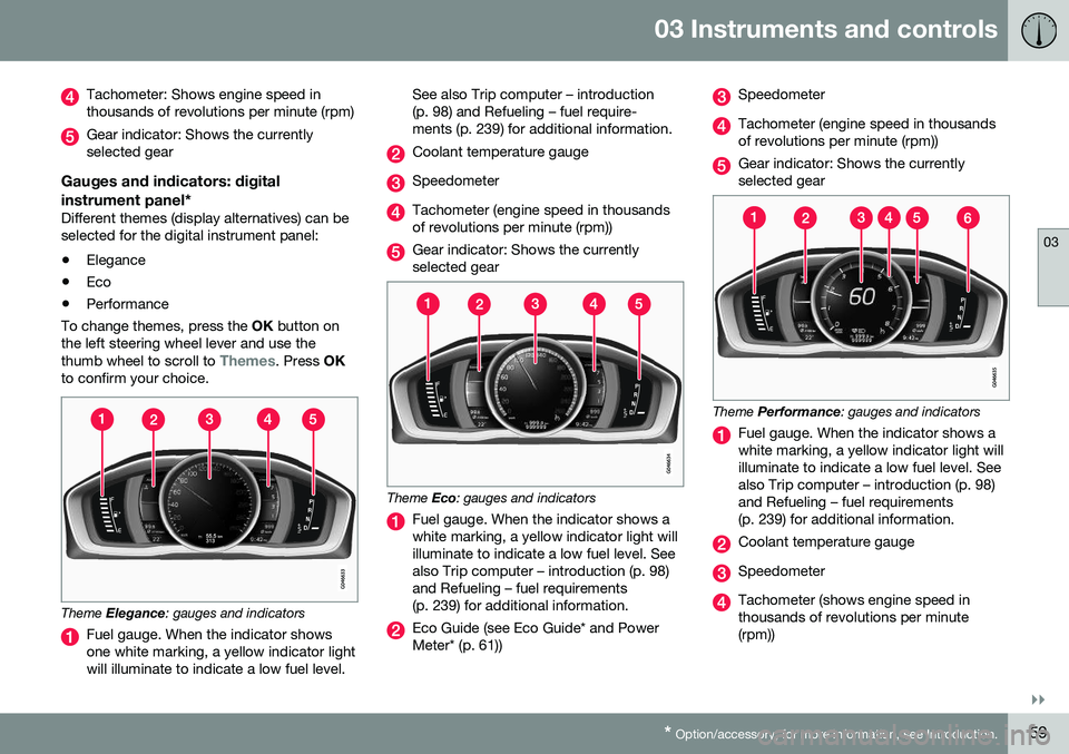
Tachometer: Shows engine speed in thousands of revolutions per minute (rpm)
Gear indicator: Shows the currently selected gear
Gauges and indicators: digital instrument panel*
Different themes (display alternatives) can be selected for the digital instrument panel: • Elegance
• Eco
• Performance
To change themes, press the OK button on
the left steering wheel lever and use the thumb wheel to scroll to
Themes. Press OK
to confirm your choice.
Theme Elegance : gauges and indicators
Fuel gauge. When the indicator shows one white marking, a yellow indicator lightwill illuminate to indicate a low fuel level. See also Trip computer – introduction(p. 98) and Refueling – fuel require-ments (p. 239) for additional information.
Coolant temperature gauge
Speedometer
Tachometer (engine speed in thousands of revolutions per minute (rpm))
Gear indicator: Shows the currently selected gear
Theme
Eco: gauges and indicators
Fuel gauge. When the indicator shows a white marking, a yellow indicator light willilluminate to indicate a low fuel level. Seealso Trip computer – introduction (p. 98)and Refueling – fuel requirements(p. 239) for additional information.
Eco Guide (see Eco Guide* and Power Meter* (p. 61))
Speedometer
Tachometer (engine speed in thousands of revolutions per minute (rpm))
Gear indicator: Shows the currently selected gear
Theme Performance : gauges and indicators
Fuel gauge. When the indicator shows a white marking, a yellow indicator light willilluminate to indicate a low fuel level. Seealso Trip computer – introduction (p. 98)and Refueling – fuel requirements(p. 239) for additional information.
Coolant temperature gauge
Speedometer
Tachometer (shows engine speed in thousands of revolutions per minute(rpm))