instrument panel VOLVO S80 2007 User Guide
[x] Cancel search | Manufacturer: VOLVO, Model Year: 2007, Model line: S80, Model: VOLVO S80 2007Pages: 251, PDF Size: 5.7 MB
Page 102 of 251
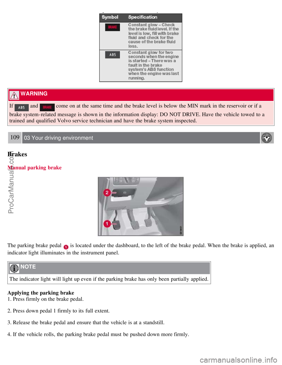
WARNING
If
and come on at the same time and the brake level is below the MIN mark in the reservoir or if a
brake system-related message is shown in the information display: DO NOT DRIVE. Have the vehicle towed to a
trained and qualified Volvo service technician and have the brake system inspected.
109 03 Your driving environment
Brakes
Manual parking brake
The parking brake pedal is located under the dashboard, to the left of the brake pedal. When the brake is applied, an
indicator light illuminates in the instrument panel.
NOTE
The indicator light will light up even if the parking brake has only been partially applied.
Applying the parking brake
1. Press firmly on the brake pedal.
2. Press down pedal 1 firmly to its full extent.
3. Release the brake pedal and ensure that the vehicle is at a standstill.
4. If the vehicle rolls, the parking brake pedal must be pushed down more firmly.
ProCarManuals.com
Page 104 of 251
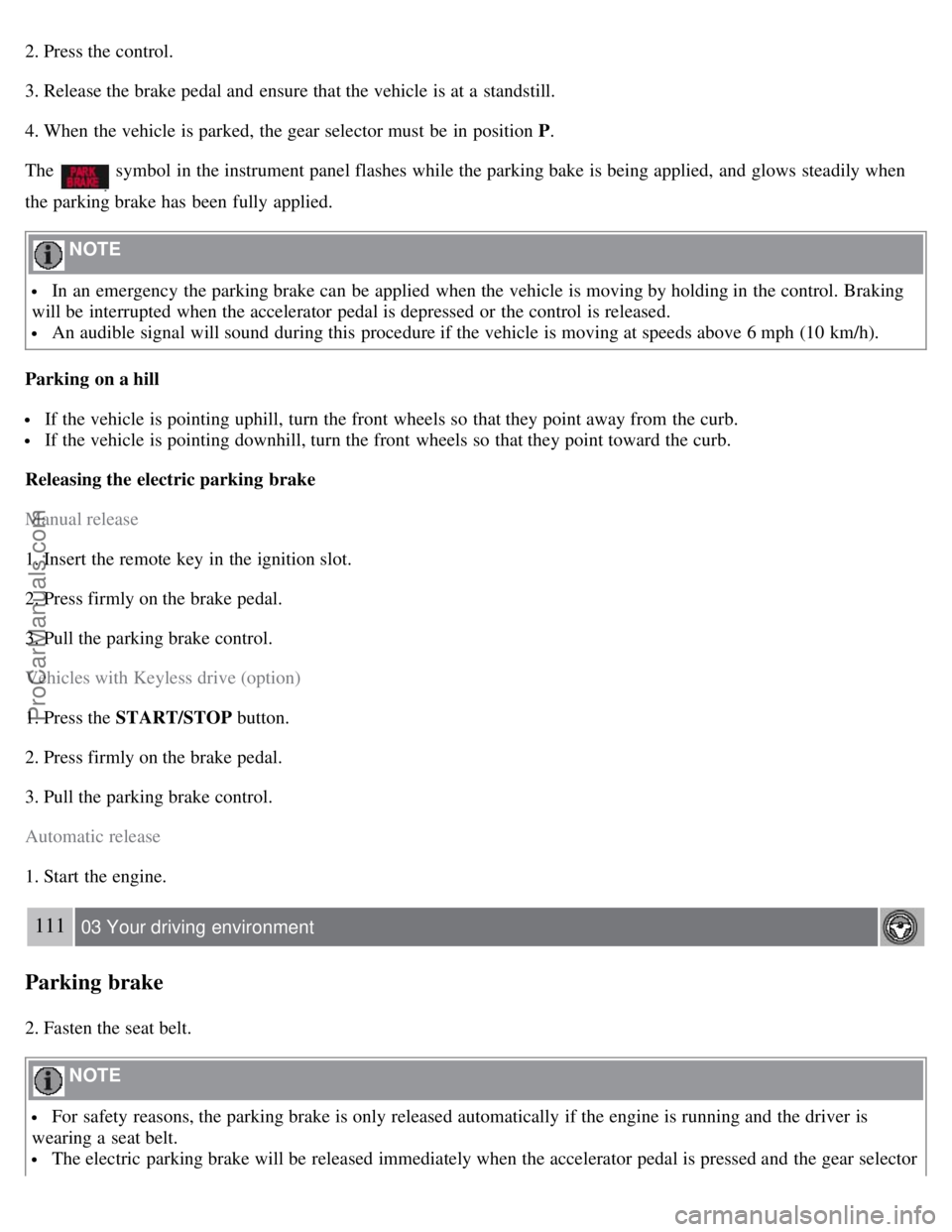
2. Press the control.
3. Release the brake pedal and ensure that the vehicle is at a standstill.
4. When the vehicle is parked, the gear selector must be in position P.
The
symbol in the instrument panel flashes while the parking bake is being applied, and glows steadily when
the parking brake has been fully applied.
NOTE
In an emergency the parking brake can be applied when the vehicle is moving by holding in the control. Braking
will be interrupted when the accelerator pedal is depressed or the control is released.
An audible signal will sound during this procedure if the vehicle is moving at speeds above 6 mph (10 km/h).
Parking on a hill
If the vehicle is pointing uphill, turn the front wheels so that they point away from the curb.
If the vehicle is pointing downhill, turn the front wheels so that they point toward the curb.
Releasing the electric parking brake
Manual release
1. Insert the remote key in the ignition slot.
2. Press firmly on the brake pedal.
3. Pull the parking brake control.
Vehicles with Keyless drive (option)
1. Press the START/STOP button.
2. Press firmly on the brake pedal.
3. Pull the parking brake control.
Automatic release
1. Start the engine.
111 03 Your driving environment
Parking brake
2. Fasten the seat belt.
NOTE
For safety reasons, the parking brake is only released automatically if the engine is running and the driver is
wearing a seat belt.
The electric parking brake will be released immediately when the accelerator pedal is pressed and the gear selector
ProCarManuals.com
Page 110 of 251
Audio settings
Main menu Bluetooth cell phone
Bluetooth (option)
Change phone
Remove phone
1The menu option for audio settings is available in all audio sources.
116 04 Comfort and driving pleasure
Menus and messages
Main instrument panel
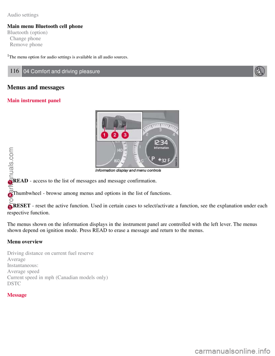
READ - access to the list of messages and message confirmation.
Thumbwheel - browse among menus and options in the list of functions.
RESET - reset the active function. Used in certain cases to select/activate a function, see the explanation under each
respective function.
The menus shown on the information displays in the instrument panel are controlled with the left lever. The menus
shown depend on ignition mode. Press READ to erase a message and return to the menus.
Menu overview
Driving distance on current fuel reserve
Average
Instantaneous:
Average speed
Current speed in mph (Canadian models only)
DSTC
Message
ProCarManuals.com
Page 137 of 251
2. Hold down the RESET button to toggle between DSTC SPIN CONTROL ON or OFF.
Messages in the information display
DSTC Temporarily OFF - system function has been temporarily reduced due to high brake disc temperature. The
function is activated automatically when the brakes have cooled.
DSTC Service required - the system has been disabled due to a fault. If this occurs:
140 04 Comfort and driving pleasure
Stability system
1. Stop the vehicle in a safe place and turn off the engine.
2. Restart the engine.
If the message remains when the engine is restarted, drive to an authorized Volvo workshop to have the system
inspected.
Symbols in the instrument panel
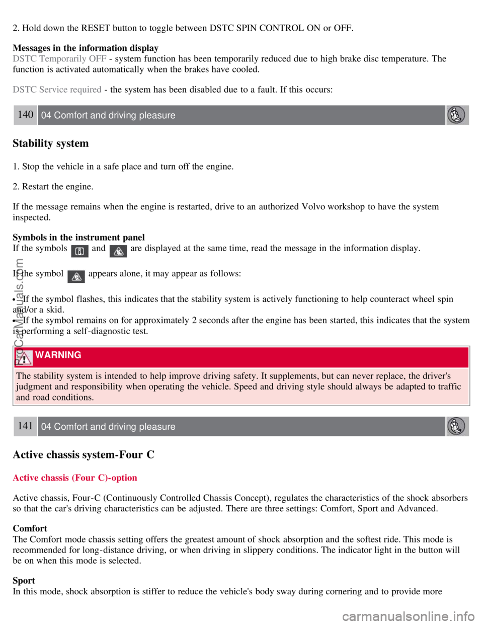
If the symbols
and are displayed at the same time, read the message in the information display.
If the symbol
appears alone, it may appear as follows:
If the symbol flashes, this indicates that the stability system is actively functioning to help counteract wheel spin
and/or a skid.
If the symbol remains on for approximately 2 seconds after the engine has been started, this indicates that the system
is performing a self -diagnostic test.
WARNING
The stability system is intended to help improve driving safety. It supplements, but can never replace, the driver's
judgment and responsibility when operating the vehicle. Speed and driving style should always be adapted to traffic
and road conditions.
141 04 Comfort and driving pleasure
Active chassis system-Four C
Active chassis (Four C)-option
Active chassis, Four-C (Continuously Controlled Chassis Concept), regulates the characteristics of the shock absorbers
so that the car's driving characteristics can be adjusted. There are three settings: Comfort, Sport and Advanced.
Comfort
The Comfort mode chassis setting offers the greatest amount of shock absorption and the softest ride. This mode is
recommended for long-distance driving, or when driving in slippery conditions. The indicator light in the button will
be on when this mode is selected.
Sport
In this mode, shock absorption is stiffer to reduce the vehicle's body sway during cornering and to provide more
ProCarManuals.com
Page 153 of 251
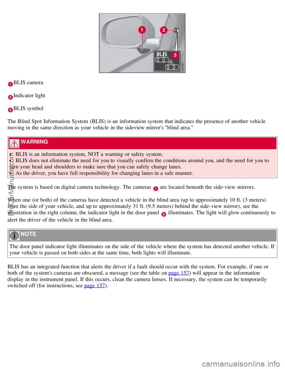
BLIS camera
Indicator light
BLIS symbol
The Blind Spot Information System (BLIS) is an information system that indicates the presence of another vehicle
moving in the same direction as your vehicle in the sideview mirror's "blind area."
WARNING
BLIS is an information system, NOT a warning or safety system.
BLIS does not eliminate the need for you to visually confirm the conditions around you, and the need for you to
turn your head and shoulders to make sure that you can safely change lanes.
As the driver, you have full responsibility for changing lanes in a safe manner.
The system is based on digital camera technology. The cameras
are located beneath the side-view mirrors.
When one (or both) of the cameras have detected a vehicle in the blind area (up to approximately 10 ft. (3 meters)
from the side of your vehicle, and up to approximately 31 ft. (9.5 meters) behind the side-view mirror), see the
illustration in the right column, the indicator light in the door panel
illuminates. The light will glow continuously to
alert the driver of the vehicle in the blind area.
NOTE
The door panel indicator light illuminates on the side of the vehicle where the system has detected another vehicle. If
your vehicle is passed on both sides at the same time, both lights will illuminate.
BLIS has an integrated function that alerts the driver if a fault should occur with the system. For example, if one or
both of the system's cameras are obscured, a message (see the table on page 157
) will appear in the information
display in the instrument panel. If this occurs, clean the camera lenses. If necessary, the system can be temporarily
switched off (for instructions, see page 157
).
ProCarManuals.com
Page 170 of 251
Volvo recommends the use of detergent gasoline to control engine deposits. Detergent gasoline is effective in keeping
injectors and intake valves clean. Consistent use of deposit control gasolines will help ensure good drivability and fuel
economy. If you are not sure whether the gasoline contains deposit control additives, check with the service station
operator.
NOTE
Volvo does not recommend the use of external fuel injector cleaning systems.
Unleaded fuel
Each Volvo has a three-way catalytic converter and must use only unleaded gasoline. U.S. and Canadian regulations
require that pumps delivering unleaded gasoline be labelled "UNLEADED". Only these pumps have nozzles which fit
your vehicle's filler inlet. It is unlawful to dispense leaded fuel into a vehicle labelled "unleaded gasoline only".
Leaded gasoline damages the three-way catalytic converter and the heated oxygen sensor system. Repeated use of
leaded gasoline will lessen the effectiveness of the emission control system and could result in loss of emission
warranty coverage. State and local vehicle inspection programs will make detection of misfueling easier, possibly
resulting in emission test failure for misfueled vehicles.
NOTE
Some U.S. and Canadian gasolines contain an octane enhancing additive called methyl- cyclopentadienyl manganese
tricarbonyl (MMT). If such fuels are used, your Emission Control System performance may be affected, and the
Check Engine Light (malfunction indicator light) located on your instrument panel may light. If this occurs, please
return your vehicle to an authorized Volvo retailer for service.
Gasoline containing alcohol and ethers, "Oxygenated fuels"
Some fuel suppliers sell gasoline containing "oxygenates" which are usually alcohols or ethers. In some areas, state or
local laws require that the service pump be marked indicating use of alcohols or ethers. However, there are areas in
which the pumps are unmarked. If you are not sure whether there is alcohol or ethers in the gasoline you buy, check
with the service station operator. To meet seasonal air quality standards, some areas require the use of "oxygenated"
fuel.
Volvo allows the use of the following "oxygenated" fuels; however, the octane ratings listed on this page must still be
met.
Alcohol - Ethanol
Fuels containing up to 10% ethanol by volume may be used. Ethanol may also be referred to as Ethyl alcohol, or
"Gasohol".
Ethers - MTBE: Fuels containing up to 15% MTBE may be used.
Methanol
Do not use gasolines containing methanol (methyl alcohol, wood alcohol). This practice can result in vehicle
performance deterioration and can damage critical parts in the fuel system. Such damage may not be covered under the
New Vehicle Limited Warranty.
175 05 During your trip
Refueling
RECOMMENDED
ProCarManuals.com
Page 217 of 251
Tire Pressure Monitoring System (TPMS) -U.S models only
The tire pressure monitoring system uses sensors mounted in the tire valves to check inflation pressure levels. When
the vehicle is moving at a speed of approximately 20 mph (30 km/h) or faster, these sensors transmit inflation pressure
data to a receiver located in the vehicle.
NOTE
USA - FCC ID: KR5S122780002
This device complies with part 15 of the FCC rules. Operation is subject to the following conditions: (1) This device
may not cause harmful interference, and (2) this device must accept any interference received, including interference
that may cause undesired operation.
When low inflation pressure is detected, TPMS will light up the tire pressure warning light (
) (also referred to as a
telltale) in the instrument panel, and will display a message in the text window. The wording of this message is
determined by the degree of inflation pressure loss.
NOTE
If a fault occurs in TPMS, the tire pressure warning light will flash for approximately 1 minute and TIRE PRESS
SYST SERVICE REQUIRED will be displayed.
Each tire, including the spare (if provided), should be checked monthly when cold and inflated to the inflation pressure
recommended by the vehicle manufacturer on the vehicle placard or tire inflation pressure label. (If your vehicle has
tires of a different size than the size indicated on the vehicle placard or tire inflation pressure label, you should
determine the proper tire inflation pressure for those tires.)
As an added safety feature, your vehicle has been equipped with a tire pressure monitoring system (TPMS) that
illuminates a low tire pressure telltale when one or more of your tires is significantly under-inflated. Accordingly,
when the low tire pressure telltale illuminates, you should stop and check your tires as soon as possible, and inflate
them to the proper pressure. Driving on a significantly under-inflated tire causes the tire to overheat and can lead to
tire failure. Under-inflation also reduces fuel efficiency and tire tread life, and may affect the vehicle's handling and
stopping ability.
Please note that the TPMS is not a substitute for proper tire maintenance, and it is the driver's responsibility to
maintain correct tire pressure, even if under-inflation has not reached the level to trigger illumination of the TPMS low
tire pressure telltale.
Your vehicle has also been equipped with a TPMS malfunction indicator to indicate when the system is not operating
properly. The TPMS malfunction indicator is combined with the low tire pressure telltale. When the system detects a
malfunction, the telltale will flash for approximately one minute and then remain continuously illuminated. This
sequence will continue upon subsequent vehicle start-ups as long as the malfunction exists. When the malfunction
indicator is illuminated, the system may not be able to detect or signal low tire pressure as intended. TPMS
malfunctions may occur for a variety of reasons, including the installation of replacement or alternate tires or wheels
on the vehicle that prevent the TPMS from functioning properly. Always check the TPMS malfunction telltale after
replacing one or more tires or wheels on your vehicle to ensure that the replacement or alternate tires and wheels allow
the TPMS to continue to function properly.
224 06 Maintenance and specifications
Wheels and tires
ProCarManuals.com
Page 219 of 251
Self supporting run flat tires
Certain models equipped with the Tire Pressure Monitoring System (TPMS) can also be equipped with self supporting
run flat tires.
Tires of this type have specially reinforced sidewalls that make it possible to continue driving in the event of a drop in
inflation pressure. Tires of this type are mounted on special rims.
NOTE
Self supporting run flat tires are only available in conjunction with TPMS.
If a self supporting run flat tire should lose inflation pressure, the yellow TPMS warning symbol (
) in the
instrument panel lights up to alert the driver, and a message will be shown in the text window in the instrument panel.
If this occurs, reduce vehicle speed to a maximum of 50 mph (80 km/h). The vehicle can be driven approximately 50
miles (80 km), or somewhat farther if the vehicle is not heavily loaded. The tire should be replaced as soon as
possible.
Hard braking and sudden steering maneuvers should be avoided.
In certain cases, it may be difficult to see which self supporting run flat tire is defective. To determine which tire is
damaged, check the inflation pressure of all four tires.
WARNING
Only specially trained persons should mount self supporting run flat tires.
If self supporting run flat tires are mounted, the vehicle must be equipped with a Tire Pressure Monitoring
System.
After a low pressure warning has been displayed, do not exceed 50 mph (80 km/h).
Avoid severe cornering and hard braking, and minimize the distance traveled before replacing the self supporting
run flat tire.
Self supporting run flat tires cannot be repaired. They must be replaced if damaged or punctured.
226 06 Maintenance and specifications
Wheels and tires
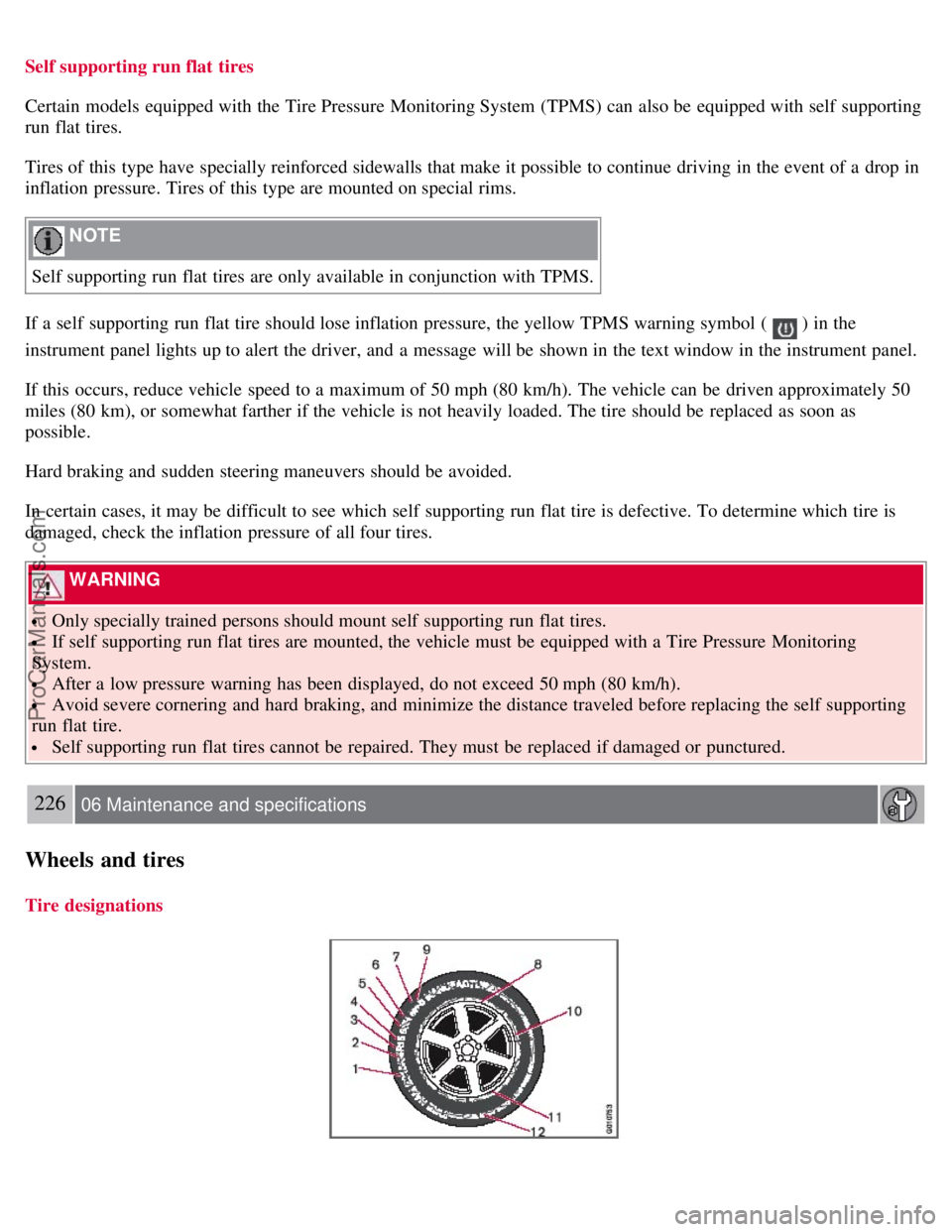
Tire designations
ProCarManuals.com
Page 244 of 251
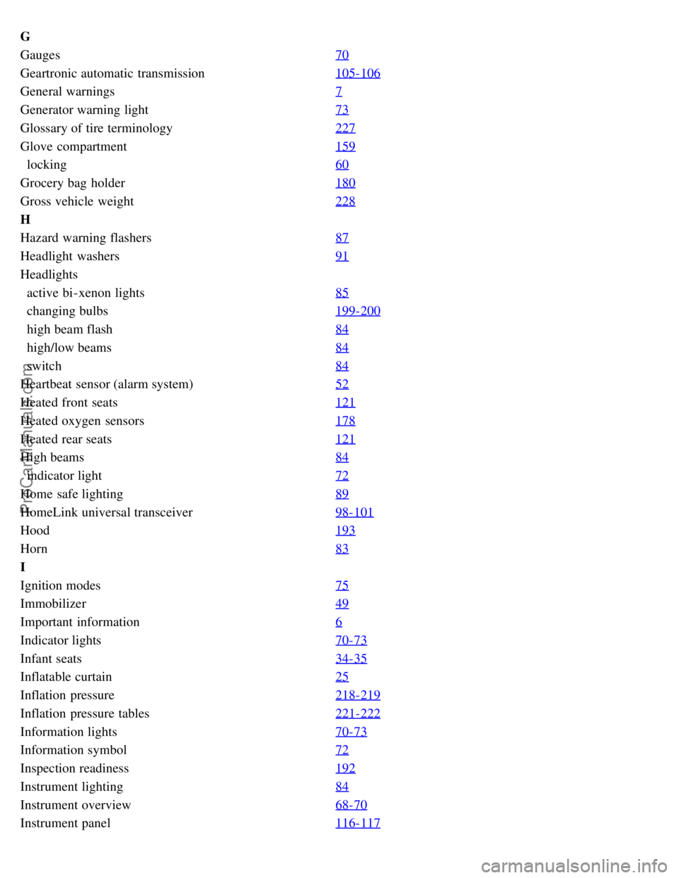
G
Gauges70
Geartronic automatic transmission105-106
General warnings7
Generator warning light73
Glossary of tire terminology227
Glove compartment159
locking60
Grocery bag holder180
Gross vehicle weight228
H
Hazard warning flashers87
Headlight washers91
Headlights
active bi-xenon lights85
changing bulbs199-200
high beam flash84
high/low beams84
switch84
Heartbeat sensor (alarm system)52
Heated front seats121
Heated oxygen sensors178
Heated rear seats121
High beams84
indicator light72
Home safe lighting89
HomeLink universal transceiver98-101
Hood193
Horn83
I
Ignition modes75
Immobilizer49
Important information6
Indicator lights70-73
Infant seats34-35
Inflatable curtain25
Inflation pressure218-219
Inflation pressure tables221-222
Information lights70-73
Information symbol72
Inspection readiness192
Instrument lighting84
Instrument overview68-70
Instrument panel116-117
ProCarManuals.com
Page 245 of 251
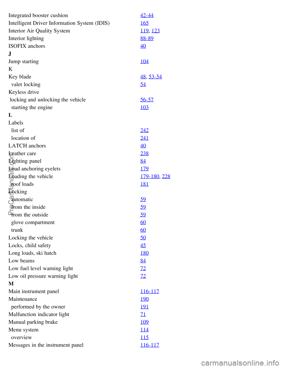
Integrated booster cushion42-44
Intelligent Driver Information System (IDIS)165
Interior Air Quality System119, 123
Interior lighting88-89
ISOFIX anchors40
J
Jump starting104
K
Key blade48
, 53-54
valet locking54
Keyless drive
locking and unlocking the vehicle56-57
starting the engine103
L
Labels
list of242
location of241
LATCH anchors40
Leather care238
Lighting panel84
Load anchoring eyelets179
Loading the vehicle179-180, 228
roof loads181
Locking
automatic59
from the inside59
from the outside59
glove compartment60
trunk60
Locking the vehicle50
Locks, child safety45
Long loads, ski hatch180
Low beams84
Low fuel level warning light72
Low oil pressure warning light72
M
Main instrument panel116-117
Maintenance190
performed by the owner191
Malfunction indicator light71
Manual parking brake109
Menu system114
overview115
Messages in the instrument panel116-117
ProCarManuals.com