sensor VOLVO S90 T8 2018 Owner´s Manual
[x] Cancel search | Manufacturer: VOLVO, Model Year: 2018, Model line: S90 T8, Model: VOLVO S90 T8 2018Pages: 166, PDF Size: 4.72 MB
Page 71 of 166
IMPORTANT INFORMATION
}}
69
Child restraints
Suitable child restraints should always be used when children travel in the vehicle.
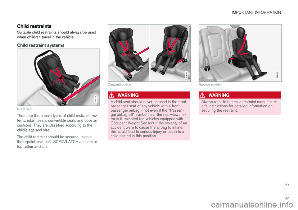
Child restraint systems
Infant seat
There are three main types of child restraint sys- tems: infant seats, convertible seats and boostercushions. They are classified according to thechild's age and size. The child restraint should be secured using a three-point seat belt, ISOFIX/LATCH anchors ortop tether anchors.
Convertible seat
WARNING
A child seat should never be used in the front passenger seat of any vehicle with a frontpassenger airbag – not even if the "Passen-ger airbag off" symbol near the rear-view mir-ror is illuminated (on vehicles equipped withOccupant Weight Sensor). If the severity of anaccident were to cause the airbag to inflate,this could lead to serious injury or death to achild seated in this position.
Booster cushion
WARNING
Always refer to the child restraint manufactur- er's instructions for detailed information onsecuring the restraint.
Page 73 of 166
IMPORTANT INFORMATION
}}
71
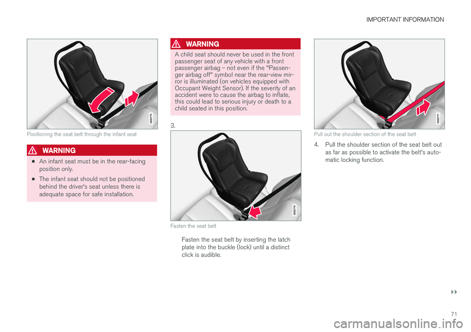
Positioning the seat belt through the infant seat
WARNING
•An infant seat must be in the rear-facing position only.
• The infant seat should not be positionedbehind the driver's seat unless there isadequate space for safe installation.
WARNING
A child seat should never be used in the front passenger seat of any vehicle with a frontpassenger airbag – not even if the "Passen-ger airbag off" symbol near the rear-view mir-ror is illuminated (on vehicles equipped withOccupant Weight Sensor). If the severity of anaccident were to cause the airbag to inflate,this could lead to serious injury or death to achild seated in this position.
3.
Fasten the seat belt
Fasten the seat belt by inserting the latch plate into the buckle (lock) until a distinctclick is audible.
Pull out the shoulder section of the seat belt
4. Pull the shoulder section of the seat belt out as far as possible to activate the belt's auto- matic locking function.
Page 79 of 166
IMPORTANT INFORMATION
77
Related information
•Top tether anchors (p. 78)Lower child seat attachment points 1
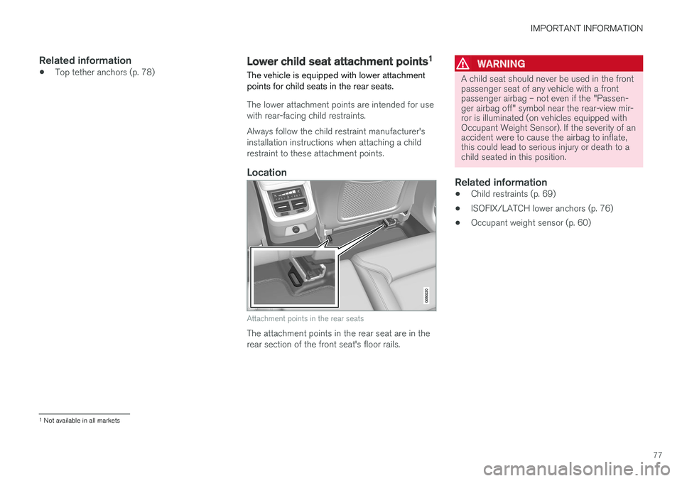
The vehicle is equipped with lower attachment points for child seats in the rear seats.
The lower attachment points are intended for use with rear-facing child restraints. Always follow the child restraint manufacturer's installation instructions when attaching a childrestraint to these attachment points.
Location
Attachment points in the rear seats
The attachment points in the rear seat are in the rear section of the front seat's floor rails.
WARNING
A child seat should never be used in the front passenger seat of any vehicle with a frontpassenger airbag – not even if the "Passen-ger airbag off" symbol near the rear-view mir-ror is illuminated (on vehicles equipped withOccupant Weight Sensor). If the severity of anaccident were to cause the airbag to inflate,this could lead to serious injury or death to achild seated in this position.
Related information
• Child restraints (p. 69)
• ISOFIX/LATCH lower anchors (p. 76)
• Occupant weight sensor (p. 60)
1
Not available in all markets
Page 86 of 166
||
PRACTICAL INFORMATION
84
NOTE
One of the alarm sensors, which is sensitive to metallic objects, is located under the tunnelconsole cup holders. Avoid leaving coins,keys, etc., in the cup holders because theymay inadvertently trigger the alarm.
Related information
•Passenger compartment storage spaces (p. 80)
• Electrical sockets (p. 115)
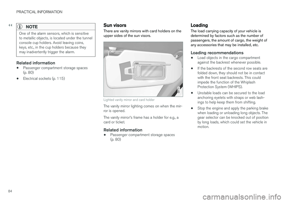
Sun visors There are vanity mirrors with card holders on the upper sides of the sun visors.
Lighted vanity mirror and card holder
The vanity mirror lighting comes on when the mir- ror is opened. The vanity mirror's frame has a holder for e.g., a card or ticket.
Related information
• Passenger compartment storage spaces(p. 80)
Loading
The load carrying capacity of your vehicle is determined by factors such as the number ofpassengers, the amount of cargo, the weight ofany accessories that may be installed, etc.
Loading recommendations
• Load objects in the cargo compartment against the backrest whenever possible.
• If the backrests of the second row seats arefolded down, they should not be in contactwith the front seat backrests. This couldimpede the function of the WhiplashProtection System (WHIPS).
• Unstable loads can be secured to the loadanchoring eyelets with straps or web lash-ings to help keep them from shifting.
• Stop the engine and apply the parking brakewhen loading or unloading long objects. Thegear selector can be knocked out of positionby long loads, which could set the vehicle inmotion.
Page 114 of 166
||
PRACTICAL INFORMATION
1129. Pump the tire for 7 minutes.
CAUTION
The compressor should not be used for more than 10 minutes at a time to avoid overheat-ing.
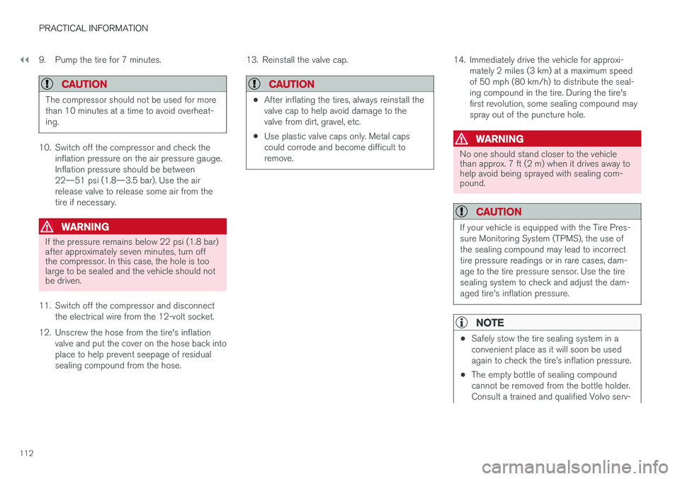
10. Switch off the compressor and check the
inflation pressure on the air pressure gauge. Inflation pressure should be between22—51 psi (1.8—3.5 bar). Use the airrelease valve to release some air from thetire if necessary.
WARNING
If the pressure remains below 22 psi (1.8 bar) after approximately seven minutes, turn offthe compressor. In this case, the hole is toolarge to be sealed and the vehicle should notbe driven.
11. Switch off the compressor and disconnect the electrical wire from the 12-volt socket.
12. Unscrew the hose from the tire's inflation valve and put the cover on the hose back into place to help prevent seepage of residualsealing compound from the hose. 13. Reinstall the valve cap.
CAUTION
•
After inflating the tires, always reinstall the valve cap to help avoid damage to thevalve from dirt, gravel, etc.
• Use plastic valve caps only. Metal capscould corrode and become difficult toremove.
14. Immediately drive the vehicle for approxi-
mately 2 miles (3 km) at a maximum speed of 50 mph (80 km/h) to distribute the seal-ing compound in the tire. During the tire'sfirst revolution, some sealing compound mayspray out of the puncture hole.
WARNING
No one should stand closer to the vehicle than approx. 7 ft (2 m) when it drives away tohelp avoid being sprayed with sealing com-pound.
CAUTION
If your vehicle is equipped with the Tire Pres- sure Monitoring System (TPMS), the use ofthe sealing compound may lead to incorrecttire pressure readings or in rare cases, dam-age to the tire pressure sensor. Use the tiresealing system to check and adjust the dam-aged tire's inflation pressure.
NOTE
•Safely stow the tire sealing system in a convenient place as it will soon be usedagain to check the tire
Page 128 of 166
||
PRACTICAL INFORMATION
* Option/accessory.
126
Via Function view
–From Function view, tap the Wiper Service
Position button. The indicator light in the
button will go out when the service position is deactivated.
Via Settings
1. Tap Settings in the center display's Top
view.
2.
My CarWipers
3. Tap the Wiper Service Position to deselect
the box.
The wipers will also leave the service position if:
• The wipers are activated.
• The windshield washers are activated.
• The rain sensor is activated.
CAUTION
If the wiper arms have been folded out from the windshield while in the service position,fold them back against the windshield beforereturning the wipers to the normal position tohelp avoid scratching the paint on the hood.
Related information
•Replacing wiper blades (p. 124)
Refilling the windshield washer fluid reservoir
Washer fluid helps keep the windshield and headlights clean.
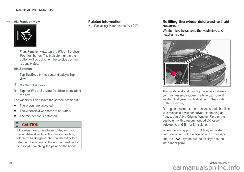
The windshield and headlight washers * share a
common reservoir. Open the blue cap to refill washer fluid (see the illustration for the locationof the reservoir). During cold weather, the reservoir should be filled with windshield washer solvent containing anti-freeze. Use Volvo Original Washer Fluid or theequivalent with a recommended pH valuebetween 6 and 8 in a 1:1 solution. When there is approx. 1 qt (1 liter) of washer fluid remaining in the reservoir, a text message and the
symbol will be displayed in the
instrument panel.
Page 135 of 166
FUSES
}}
* Option/accessory.133
•
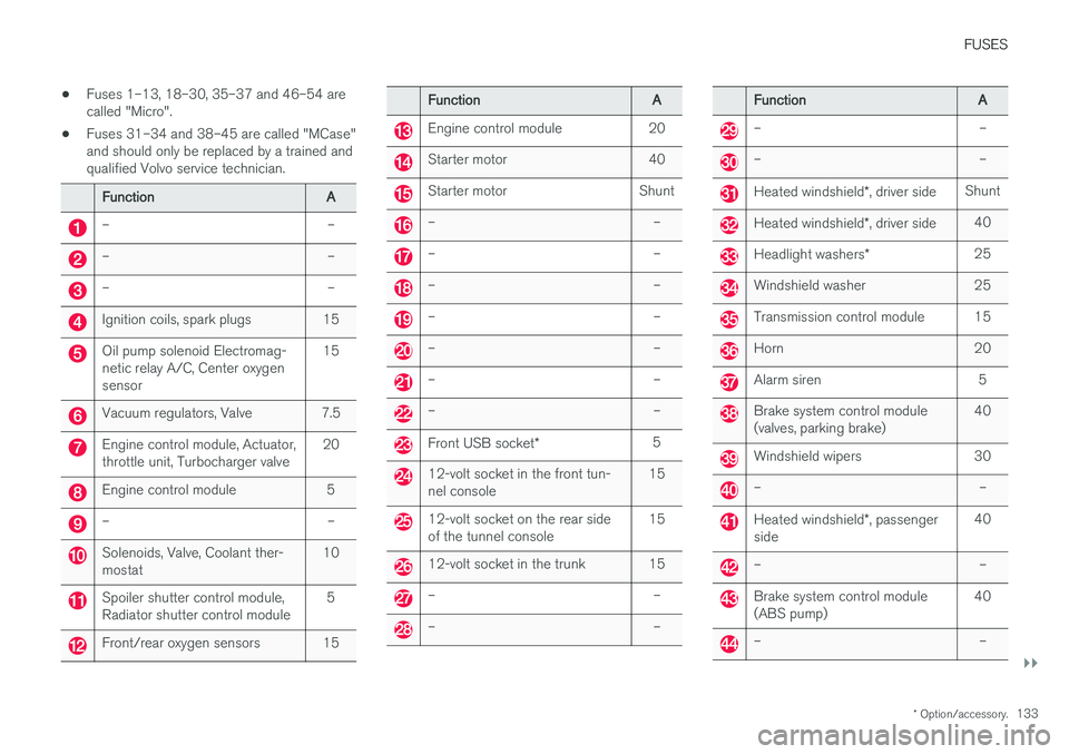
Fuses 1–13, 18–30, 35–37 and 46–54 are called "Micro".
• Fuses 31–34 and 38–45 are called "MCase"and should only be replaced by a trained andqualified Volvo service technician.
Function
A
– –
– –
– –
Ignition coils, spark plugs 15
Oil pump solenoid Electromag- netic relay A/C, Center oxygensensor15
Vacuum regulators, Valve 7.5
Engine control module, Actuator, throttle unit, Turbocharger valve
20
Engine control module 5
– –
Solenoids, Valve, Coolant ther- mostat10
Spoiler shutter control module, Radiator shutter control module 5
Front/rear oxygen sensors 15
Function
A
Engine control module 20
Starter motor 40
Starter motor Shunt
– –
– –
– –
– –
– –
– –
– –
Front USB socket* 5
12-volt socket in the front tun- nel console 15
12-volt socket on the rear side of the tunnel console15
12-volt socket in the trunk 15
– –
– –
Function
A
– –
– –
Heated windshield*, driver side Shunt
Heated windshield
*, driver side 40
Headlight washers
*25
Windshield washer 25
Transmission control module 15
Horn 20
Alarm siren 5
Brake system control module (valves, parking brake) 40
Windshield wipers 30
– –
Heated windshield
*, passenger
side 40
– –
Brake system control module (ABS pump)
40
– –
Page 136 of 166
||
FUSES
* Option/accessory.
134
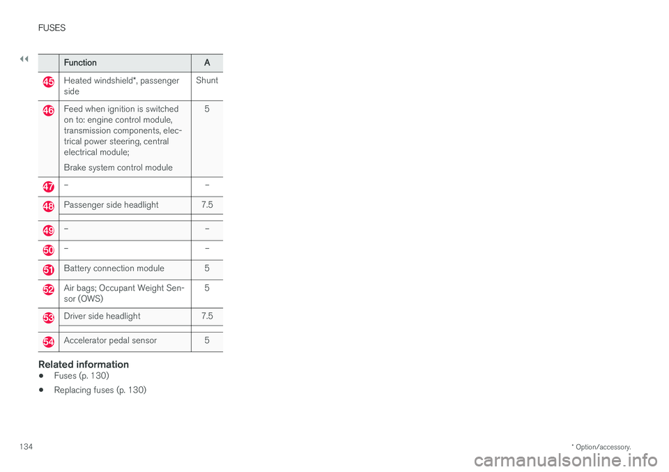
Function A
Heated windshield*, passenger
side Shunt
Feed when ignition is switched on to: engine control module,transmission components, elec-trical power steering, centralelectrical module; Brake system control module 5
– –
Passenger side headlight 7.5
– –
– –
Battery connection module 5
Air bags; Occupant Weight Sen- sor (OWS)
5
Driver side headlight 7.5
Accelerator pedal sensor 5
Related information
•
Fuses (p. 130)
• Replacing fuses (p. 130)
Page 139 of 166
FUSES
}}
* Option/accessory.137
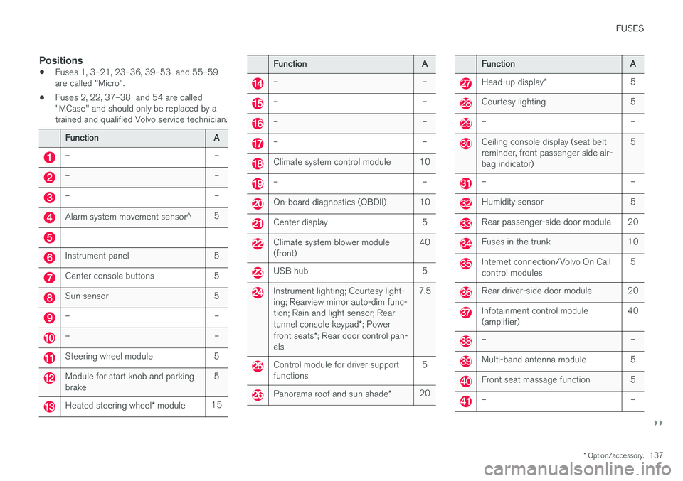
Positions
•Fuses 1, 3–21, 23–36, 39–53 and 55–59 are called "Micro".
• Fuses 2, 22, 37–38 and 54 are called"MCase" and should only be replaced by atrained and qualified Volvo service technician.
Function
A
– –
– –
– –
Alarm system movement sensorA
5
Instrument panel 5
Center console buttons 5
Sun sensor 5
– –
– –
Steering wheel module 5
Module for start knob and parking brake 5
Heated steering wheel
* module 15
Function
A
– –
– –
– –
– –
Climate system control module 10
– –
On-board diagnostics (OBDII) 10
Center display 5
Climate system blower module (front)40
USB hub 5
Instrument lighting; Courtesy light- ing; Rearview mirror auto-dim func-tion; Rain and light sensor; Rear tunnel console keypad
*; Power
front seats *; Rear door control pan-
els 7.5
Control module for driver support functions
5
Panorama roof and sun shade
*20
Function
A
Head-up display* 5
Courtesy lighting 5
– –
Ceiling console display (seat belt reminder, front passenger side air-bag indicator) 5
– –
Humidity sensor 5
Rear passenger-side door module 20
Fuses in the trunk 10
Internet connection/Volvo On Call control modules
5
Rear driver-side door module 20
Infotainment control module (amplifier)40
– –
Multi-band antenna module 5
Front seat massage function 5
– –