warning VOLVO V60 2014 Owners Manual
[x] Cancel search | Manufacturer: VOLVO, Model Year: 2014, Model line: V60, Model: VOLVO V60 2014Pages: 442, PDF Size: 13.85 MB
Page 349 of 442
10 Maintenance and service
10
}}
347
WARNING
Never fill above the MAX mark. The level
should never be above MAX or below MIN
as this could lead to engine damage.
WARNING
Do not spill oil onto the hot exhaust mani- fold due to the risk of fire.
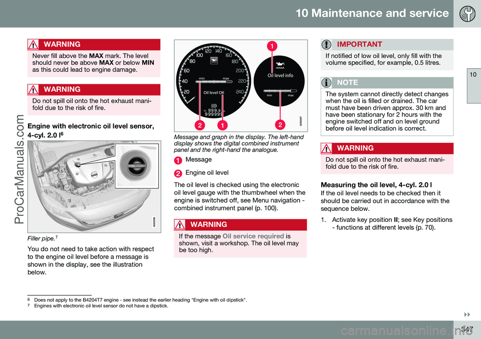
Engine with electronic oil level sensor, 4-cyl. 2.0 l 6
Filler pipe.
7
You do not need to take action with respect to the engine oil level before a message isshown in the display, see the illustrationbelow.
Message and graph in the display. The left-hand display shows the digital combined instrumentpanel and the right-hand the analogue.
Message
Engine oil level
The oil level is checked using the electronic oil level gauge with the thumbwheel when theengine is switched off, see Menu navigation -combined instrument panel (p. 100).
WARNING
If the message Oil service required is
shown, visit a workshop. The oil level may be too high.
IMPORTANT
If notified of low oil level, only fill with the volume specified, for example, 0.5 litres.
NOTE
The system cannot directly detect changes when the oil is filled or drained. The carmust have been driven approx. 30 km andhave been stationary for 2 hours with theengine switched off and on level groundbefore oil level indication is correct.
WARNING
Do not spill oil onto the hot exhaust mani- fold due to the risk of fire.
Measuring the oil level, 4-cyl. 2.0 lIf the oil level needs to be checked then it should be carried out in accordance with thesequence below.
1. Activate key position II; see Key positions
- functions at different levels (p. 70).
6 Does not apply to the B4204T7 engine - see instead the earlier heading "Engine with oil dipstick".7
Engines with electronic oil level sensor do not have a dipstick.
ProCarManuals.co’
Page 350 of 442
||
10 Maintenance and service
10
348
2. Rotate the thumbwheel on the left-handstalk switch to position Oil level.
> You will then see information displayed about the engine oil level. For more information on menu naviga- tion, see Menu navigation - combinedinstrument panel (p. 100).
NOTE
If the right conditions for measuring the oil level are not met (time after engine shut-down, the car's inclination, outside tem- perature, etc.) then the message
Not
available will be shown. This does not
mean that there is something wrong in the car's systems.
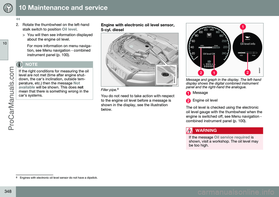
Engine with electronic oil level sensor, 5-cyl. diesel
Filler pipe. 8
You do not need to take action with respect to the engine oil level before a message isshown in the display, see the illustrationbelow.
Message and graph in the display. The left-hand display shows the digital combined instrumentpanel and the right-hand the analogue.
Message
Engine oil level
The oil level is checked using the electronic oil level gauge with the thumbwheel when theengine is switched off, see Menu navigation -combined instrument panel (p. 100).
WARNING
If the message Oil service required is
shown, visit a workshop. The oil level may be too high.
8 Engines with electronic oil level sensor do not have a dipstick.
ProCarManuals.co’
Page 351 of 442
10 Maintenance and service
10
349
IMPORTANT
In the event of the message Oil level low
Refill 0.5 litre, only fill with 0.5 litres.
NOTE
The oil level is only detected by the system during driving. The system cannot directlydetect changes when the oil is filled ordrained. The car must be drivenabout 30 km before the oil level display iscorrect.
WARNING
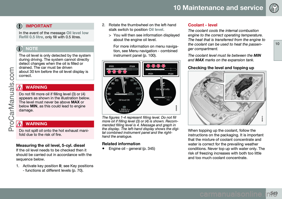
Do not fill more oil if filling level (3) or (4) appears as shown in the illustration below.The level must never be above MAX or
below MIN, as this could lead to engine
damage.
WARNING
Do not spill oil onto the hot exhaust mani- fold due to the risk of fire.
Measuring the oil level, 5-cyl. dieselIf the oil level needs to be checked then it should be carried out in accordance with thesequence below.
1. Activate key position II; see Key positions
- functions at different levels (p. 70). 2. Rotate the thumbwheel on the left-hand
stalk switch to position
Oil level.
> You will then see information displayed about the engine oil level. For more information on menu naviga- tion, see Menu navigation - combinedinstrument panel (p. 100).
The figures 1-4 represent filling level. Do not fill more oil if filling level (3) or (4) is shown. Recom-mended filling level is 4. Message and graph inthe display. The left-hand display shows the digi-tal combined instrument panel and the right-hand the analogue.
Related information
• Engine oil - general (p. 345)
Coolant - level
The coolant cools the internal combustion engine to the correct operating temperature.The heat that is transferred from the engine tothe coolant can be used to heat the passen-ger compartment. The coolant level must lie between the
MIN
and MAX marks on the expansion tank.
Checking the level and topping up
When topping up the coolant, follow the instructions on the packaging. It is importantthat the mixture of coolant concentrate andwater is correct for the prevailing weatherconditions. Never top up with water only. Therisk of freezing increases with both too littleand too much coolant concentrate.
ProCarManuals.co’
Page 352 of 442
||
10 Maintenance and service
10
350
WARNING
Coolant can be very hot. If the coolant requires topping up when the engine is atoperating temperature, unscrew theexpansion tank cap slowly to gentlyrelease the overpressure.
For capacities and for standards regarding water quality; see Coolant - grade and vol-ume (p. 398).
Check the coolant regularlyThe level must lie between the MIN and MAX
marks on the expansion tank. If the system isnot filled sufficiently, high temperatures couldoccur, causing a risk of damage to theengine.
IMPORTANT
• A high content of chlorine, chlorides and other salts may cause corrosion inthe cooling system.
• Always use coolant with anti-corrosionagent as recommended by Volvo.
• Ensure that the coolant mixture is 50%water and 50% coolant.
• Mix the coolant with approved qualitytap water. In the event of any doubtabout water quality, used ready-mixedcoolant in accordance with Volvo rec-ommendations.
• When changing coolant/replacingcooling system components, flush thecooling system clean with approvedquality tap water or flush with ready-mixed coolant.
• The engine must only be run with awell-filled cooling system. Otherwise,temperatures that are too high mayoccur resulting in the risk of damage(cracks) in the cylinder head.
Brake and clutch fluid - level
Brake and clutch fluid level should be between the reservoir
MIN and MAX marks.
Checking the levelBrake and clutch fluid have a common reser-voir. The level must be between the MIN and
MAX marks that are visible inside the reser-
voir. Check the level regularly. Change the brake fluid every other year or at every other regular service. For capacities and recommended brake fluid grade, see Brake fluid - grade and volume (p.401). The fluid should be changed annually oncars driven in conditions requiring hard, fre-quent braking, such as driving in mountainsor tropical climates with high humidity.
WARNING
If the brake fluid is under the MIN level in
the brake fluid reservoir, do not drive fur- ther before topping up the brake fluid.Volvo recommends that the reason for theloss of brake fluid is investigated by anauthorised Volvo workshop.
ProCarManuals.co’
Page 354 of 442
10 Maintenance and service
10
352
Climate control system - fault tracing and repair
The air conditioning system must only be serviced and repaired by an authorised work-shop.
Troubleshooting and repairThe air conditioning system contains fluores-cent tracing agents. Use ultraviolet light whenlooking for leaks. Volvo recommends that you contact an authorised Volvo workshop.
WARNING
The air conditioning system contains pres- surised refrigerant R134a. This systemmust only be serviced and repaired by anauthorised workshop.
Related information
•Volvo service programme (p. 340)
Lamp replacement
Lamp replacement can be carried out for bulbs. When replacing LED and Xenon lamps,please refer to a workshop. The bulbs are specified (p. 358). The follow- ing list contains locations of bulbs and otherlight sources that are specialised, such as LED 10
lamps, or are unsuitable for changing
for some other reason, except at a workshop:
• Active Xenon headlamps - ABL (Xenon lamps)
• Daytime running lights/Position/parkinglamps front
• Side marker lamps front
• Cornering lights
• Side direction indicators, door mirrors
• Approach lighting, door mirrors
• Interior lighting apart from Courtesy light-ing front
• Glovebox lighting
• Position/parking lamps rear/Side markerlamps rear
• Brake light.WARNING
On cars with Xenon headlamps, the replacement of Xenon lamps must be car-ried out at a workshop - an authorisedVolvo workshop is recommended. Workingwith Xenon lamps demands extreme cau-tion because the headlamp is equippedwith a high voltage unit.
WARNING
The car's electrical system must be in key position
0 for bulb replacement; see Key
positions - functions at different levels (p.70).
IMPORTANT
Never touch the glass part of the bulbs with your fingers. Grease from your fingersis vaporised by the heat, coating thereflector and then causing damage.
NOTE
If an error message remains after the bro- ken bulb has been replaced then we rec-ommend that you visit an authorised Volvoworkshop.
10 LED (Light Emitting Diode)
ProCarManuals.co’
Page 363 of 442
10 Maintenance and service
10
361
1. Fold out the wiper arm.
2. Grip the inner section of the blade (by the arrow).
3. Turn anticlockwise to use the blade's end position against the wiper arm as a lever to detach the blade more easily.
4. Press the new wiper blade into position. Check that it is firmly installed.
5. Lower the wiper arm.
CleaningFor cleaning wiper blades and windscreen,see Car washing (p. 379).
IMPORTANT
Check the blades regularly. Neglected maintenance shortens the service life ofthe wiper blades.
Related information
• Washer fluid - filling (p. 361)
Washer fluid - filling
Washer fluid is used for cleaning the head- lamps and windows. Washer fluid with anti-freeze must be used during winter.
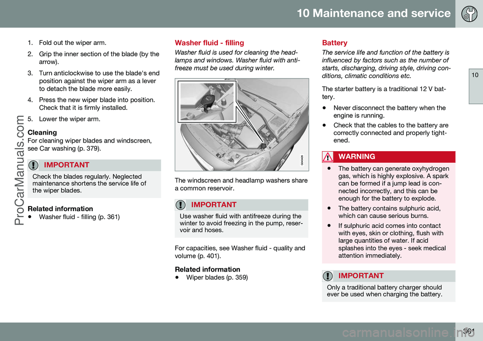
The windscreen and headlamp washers share a common reservoir.
IMPORTANT
Use washer fluid with antifreeze during the winter to avoid freezing in the pump, reser-voir and hoses.
For capacities, see Washer fluid - quality and volume (p. 401).
Related information
•Wiper blades (p. 359)
Battery
The service life and function of the battery is influenced by factors such as the number ofstarts, discharging, driving style, driving con-ditions, climatic conditions etc. The starter battery is a traditional 12 V bat- tery.
• Never disconnect the battery when the engine is running.
• Check that the cables to the battery arecorrectly connected and properly tight-ened.
WARNING
•The battery can generate oxyhydrogen gas, which is highly explosive. A sparkcan be formed if a jump lead is con-nected incorrectly, and this can beenough for the battery to explode.
• The battery contains sulphuric acid,which can cause serious burns.
• If sulphuric acid comes into contactwith eyes, skin or clothing, flush withlarge quantities of water. If acidsplashes into the eyes - seek medicalattention immediately.
IMPORTANT
Only a traditional battery charger should ever be used when charging the battery.
ProCarManuals.co’
Page 364 of 442
||
10 Maintenance and service
10
362
IMPORTANT
If the following instruction is not observed then the energy saving function for info-tainment may be temporarily disengaged,and/or the message in the information dis-play about the main battery's state ofcharge may be temporarily inapplicable,following the connection of an externalbattery or battery charger:
• The negative battery terminal on the car's starter battery must
never be
used for connecting an external bat-tery or battery charger - only the car
chassis may be used as the ground-
ing point.
See Jump starting with battery (p. 270) for a description of how the cable clampsmust be attached.
NOTE
The life of the battery is shortened if it becomes discharged repeatedly. The life of the battery is affected by several factors, including driving conditions andclimate. Battery starting capacity decrea-ses gradually with time and thereforeneeds to be recharged if the car is notused for a longer time or when it is onlydriven short distances. Extreme cold fur-ther limits starting capacity. To maintain the battery in good condition, at least 15 minutes of driving/week is rec-ommended or that the battery is con-nected to a battery charger with automatictrickle charging. A battery that is kept fully charged has a maximum service life.
Related information
• Battery - symbols (p. 362)
• Starter battery - replacement (p. 363)
• Battery - Start/Stop (p. 365)
Battery - symbols
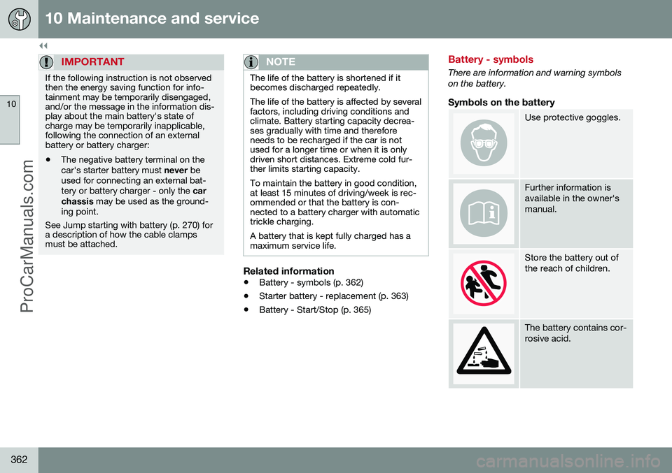
There are information and warning symbols on the battery.
Symbols on the battery
Use protective goggles.
Further information is available in the owner'smanual.
Store the battery out of the reach of children.
The battery contains cor- rosive acid.
ProCarManuals.co’
Page 366 of 442
||
10 Maintenance and service
10
364* Option/accessory, for more information, see Introduction.
Remove the rear cover by screwing one quarter turn and lifting it away.
WARNING
Connect and remove the positive and neg- ative cables in the correct order.
Detach the black negative cable.
Detach the red positive cable.
Detach the ventilation hose from the bat- tery.
Loosen the screw holding the battery clamp.
Move the battery aside.
Lift it up.
Cross-stay on the R-Design*
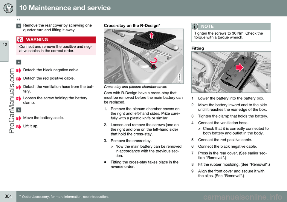
Cross-stay and plenum chamber cover.
Cars with R-Design have a cross-stay that must be removed before the main battery canbe replaced.
1. Remove the plenum chamber covers on the right and left-hand sides. Prize care- fully with a plastic knife or similar.
2. Loosen and remove the screws (one on the right and one on the left-hand side)that hold the cross-stay.
3. Remove the cross-stay. > Now the main battery can be removedin accordance with the previous sec-tion.
• Fitting the cross-stay takes place in the reverse order.
NOTE
Tighten the screws to 30 Nm. Check the torque with a torque wrench.
Fitting
1. Lower the battery into the battery box.
2. Move the battery inward and to the side
until it reaches the rear edge of the box.
3. Tighten the clamp that holds the battery.
4. Connect the ventilation hose. > Check that it is correctly connected toboth battery and outlet in the body.
5. Connect the red positive cable.
6. Connect the black negative cable.
7. Press in the rear cover. (See earlier sec- tion "Removal".)
8. Fit the rubber moulding. (See "Removal".)
9. Align the front cover and secure it with the clips. (See "Removal".)
ProCarManuals.co’
Page 369 of 442
10 Maintenance and service
10
367
Fuses - general
All electrical functions and components are protected by a number of fuses in order toprotect the car's electrical system from dam-age by short circuiting or overloading. If an electrical component or function does not work, it may be because the component'sfuse was temporarily overloaded and failed. Ifthe same fuse fails repeatedly then there is afault in the circuit. Volvo recommends thatyou visit an authorised Volvo workshop forchecking.
Changing1. Look in the fuse diagram to locate thefuse.
2. Pull out the fuse and check from the side to see whether the curved wire hasblown.
3. If this is the case, replace it with a new fuse of the same colour and amperage.
WARNING
Never use a foreign object or a fuse with an amperage higher than that specifiedwhen replacing a fuse. This could causesignificant damage to the electrical systemand possibly lead to fire.
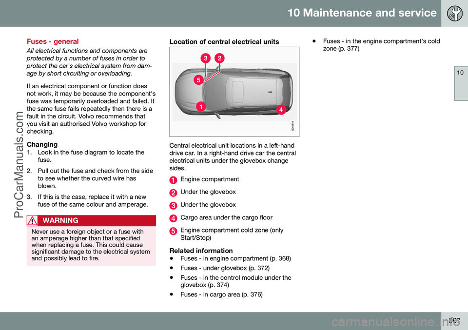
Location of central electrical units
Central electrical unit locations in a left-hand drive car. In a right-hand drive car the centralelectrical units under the glovebox changesides.
Engine compartment
Under the glovebox
Under the glovebox
Cargo area under the cargo floor
Engine compartment cold zone (only Start/Stop)
Related information
• Fuses - in engine compartment (p. 368)
• Fuses - under glovebox (p. 372)
• Fuses - in the control module under the glovebox (p. 374)
• Fuses - in cargo area (p. 376) •
Fuses - in the engine compartment's coldzone (p. 377)
ProCarManuals.co’
Page 376 of 442

10 Maintenance and service
10
374* Option/accessory, for more information, see Introduction.
Fuses - in the control module under the glovebox
Fuses in the control module under the glove- box protect airbag and collision warning sys-tem functions, amongst other things.
Positions
FunctionA
Rear window wiper15
––
Interior lighting; Driver's door control panel, power windows;Remote controlled garage dooropener*; Power seats, front*7,5
FunctionA
Combined instrument panel5
Adaptive cruise control, ACC*; collision warning system*10
Interior lighting; Rain sensor7,5
Steering wheel module7,5
Central locking system, fuel filler flap10
FunctionA
Heated steering wheel*15
Heated windscreen*15
Unlocking, tailgate10
Folding head restraint*10
Fuel pump20
ProCarManuals.co’