glove box VOLVO V60 2014 User Guide
[x] Cancel search | Manufacturer: VOLVO, Model Year: 2014, Model line: V60, Model: VOLVO V60 2014Pages: 442, PDF Size: 13.85 MB
Page 159 of 442
06 Locks and alarm
06
157
G017870
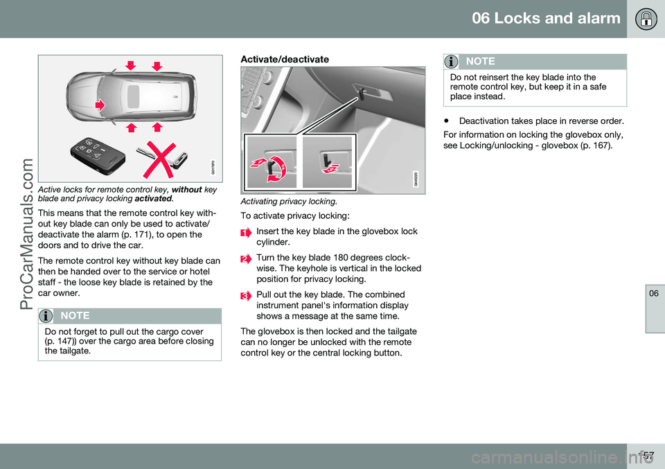
Active locks for remote control key, without key
blade and privacy locking activated.
This means that the remote control key with- out key blade can only be used to activate/deactivate the alarm (p. 171), to open thedoors and to drive the car. The remote control key without key blade can then be handed over to the service or hotelstaff - the loose key blade is retained by thecar owner.
NOTE
Do not forget to pull out the cargo cover (p. 147)) over the cargo area before closingthe tailgate.
Activate/deactivate
Activating privacy locking.
To activate privacy locking:
Insert the key blade in the glovebox lock cylinder.
Turn the key blade 180 degrees clock- wise. The keyhole is vertical in the lockedposition for privacy locking.
Pull out the key blade. The combined instrument panel's information displayshows a message at the same time.
The glovebox is then locked and the tailgatecan no longer be unlocked with the remotecontrol key or the central locking button.
NOTE
Do not reinsert the key blade into the remote control key, but keep it in a safeplace instead.
• Deactivation takes place in reverse order.
For information on locking the glovebox only, see Locking/unlocking - glovebox (p. 167).
ProCarManuals.co’
Page 163 of 442
06 Locks and alarm
06
* Option/accessory, for more information, see Introduction.161
Keyless drive* - locking
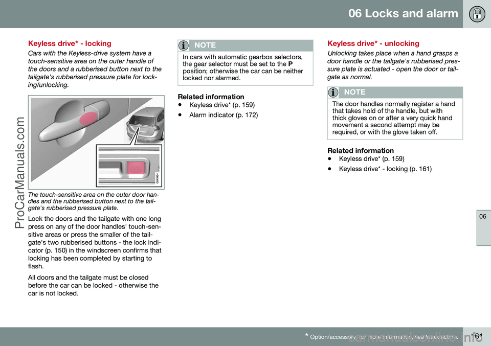
Cars with the Keyless-drive system have a touch-sensitive area on the outer handle ofthe doors and a rubberised button next to thetailgate's rubberised pressure plate for lock-ing/unlocking.
The touch-sensitive area on the outer door han- dles and the rubberised button next to the tail-gate's rubberised pressure plate.
Lock the doors and the tailgate with one long press on any of the door handles' touch-sen-sitive areas or press the smaller of the tail-gate's two rubberised buttons - the lock indi-cator (p. 150) in the windscreen confirms thatlocking has been completed by starting toflash. All doors and the tailgate must be closed before the car can be locked - otherwise thecar is not locked.
NOTE
In cars with automatic gearbox selectors, the gear selector must be set to the P
position; otherwise the car can be neitherlocked nor alarmed.
Related information
• Keyless drive* (p. 159)
• Alarm indicator (p. 172)
Keyless drive* - unlocking
Unlocking takes place when a hand grasps a door handle or the tailgate's rubberised pres-sure plate is actuated - open the door or tail-gate as normal.
NOTE
The door handles normally register a hand that takes hold of the handle, but withthick gloves on or after a very quick handmovement a second attempt may berequired, or with the glove taken off.
Related information
•
Keyless drive* (p. 159)
• Keyless drive* - locking (p. 161)
ProCarManuals.co’
Page 169 of 442
06 Locks and alarm
06
* Option/accessory, for more information, see Introduction.167
Locking/unlocking - glovebox
The glovebox (p. 140) can only be locked/ unlocked using the detachable key blade fromthe remote control key. For information on the key blade, see Detach- able key blade - detaching/attaching (p. 155).
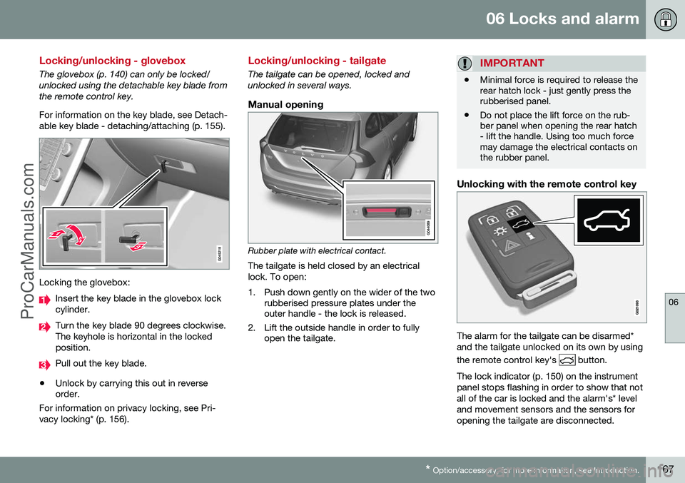
Locking the glovebox:
Insert the key blade in the glovebox lock cylinder.
Turn the key blade 90 degrees clockwise. The keyhole is horizontal in the lockedposition.
Pull out the key blade.
• Unlock by carrying this out in reverse order.
For information on privacy locking, see Pri- vacy locking* (p. 156).
Locking/unlocking - tailgate
The tailgate can be opened, locked and unlocked in several ways.
Manual opening
Rubber plate with electrical contact.
The tailgate is held closed by an electrical lock. To open:
1. Push down gently on the wider of the two rubberised pressure plates under the outer handle - the lock is released.
2. Lift the outside handle in order to fully open the tailgate.
IMPORTANT
• Minimal force is required to release the rear hatch lock - just gently press therubberised panel.
• Do not place the lift force on the rub-ber panel when opening the rear hatch- lift the handle. Using too much forcemay damage the electrical contacts onthe rubber panel.
Unlocking with the remote control key
The alarm for the tailgate can be disarmed* and the tailgate unlocked on its own by using the remote control key's
button.
The lock indicator (p. 150) on the instrument panel stops flashing in order to show that notall of the car is locked and the alarm's* leveland movement sensors and the sensors foropening the tailgate are disconnected.
ProCarManuals.co’
Page 261 of 442
08 Starting and driving
08
* Option/accessory, for more information, see Introduction.259
Alcolock*
The function of the Alcolock 1
is to prevent the
car from being driven by individuals under the influence of alcohol. Before the engine can bestarted the driver must take a breath test thatverifies that he/she is not under the influenceof alcohol. Alcolock calibration takes place inaccordance with each market's limit value inforce for driving legally.
WARNING
The Alcolock is an aid and does not exempt the driver from responsibility. It isalways the responsibility of the driver to besober and to drive the car safely.
Related information
• Alcolock* - functions and operation (p. 259)
• Alcolock* - to bear in mind (p. 261)
• Alcolock* - storage (p. 260)
• Alcolock* - before starting the engine (p.260)
• Alcolock* - symbols and text messages(p. 263)
Alcolock* - functions and operation
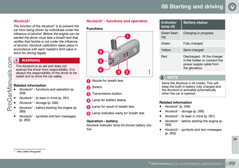
Functions
Nozzle for breath test.
Switch.
Transmission button.
Lamp for battery status.
Lamp for result of breath test.
Lamp indicates ready for breath test.
Operation - batteryAlcolock indicator lamp (4) shows battery sta- tus:
Indicator lamp (4)Battery status
Green flash- ingCharging in progress
GreenFully charged
YellowSemi-charged
RedDischarged - fit the charger in the holder or connect thepower supply cable fromthe glovebox.
NOTE
Store the Alcolock in its holder. This will keep the built-in battery fully charged andthe Alcolock is activated automaticallywhen the car is opened.
Related information
•Alcolock* (p. 259)
• Alcolock* - storage (p. 260)
• Alcolock* - to bear in mind (p. 261)
• Alcolock* - before starting the engine (p. 260)
• Alcolock* - symbols and text messages(p. 263)
1
Also called Alcoguard.
ProCarManuals.co’
Page 264 of 442
||
08 Starting and driving
08
262* Option/accessory, for more information, see Introduction.
Calibration and serviceThe Alcolock must be checked and calibrated at a workshop 2
every 12 months.
30 days before recalibration is necessary the combined instrument panel shows the mes- sage
Alcoguard Calibr. required. If calibra-
tion is not carried out within these 30 days then normal engine starting will be blocked -only starting with the Bypass function willthen be possible, see the following heading"Emergency situation". The message can be cleared by pressing the send button (3) once. Otherwise it goes outon its own after approx. 2 minutes but thenreappears each time the engine is started - only recalibration at a workshop 2
can clear
the message permanently.
Cold or hot weatherThe colder the weather the longer it takes before the Alcolock is ready for use:
Temperature (ºC)Maximum heat-
ing time (sec- onds)
+10 to +8510
-5 to +1060
-40 to -5180
At temperatures below -20 ºC or above +60 ºC the Alcolock requires additional powersupply. The combined instrument panel shows
Alcoguard insert power cable. In
which case, connect the power supply cable from the glovebox and wait until indicatorlamp (6) is green. In extremely cold weather the heating time can be reduced by taking the Alcolockindoors.
Emergency situationIn the event of an emergency situation or theAlcolock is out of order, it is possible tobypass the Alcolock in order to drive the car.
NOTE
All Bypass activation is logged and saved in memory, see Recording data (p. 16).
After the Bypass function has been activated the combined instrument panel shows
Alcoguard Bypass enabled the whole time
while driving and can only be reset by a work- shop 2
.
The Bypass function can be tested without the error message being logged - in whichcase, carry out all the steps without startingthe car. The error message is cleared whenthe car is locked. When the Alcolock is installed, either theBypass or Emergency function is selected asthe bypassing option. This setting can be changed afterwards at a workshop
2
.
Activating the Bypass function
• Depress and hold the left-hand stalk switch
OK button and the button for haz-
ard warning flashers simultaneously forapprox. 5 seconds - the combined instru- ment panel first shows
Bypass activated
Wait 1 minute and then Alcoguard
Bypass enabled - after which the engine
can be started.
This function can be activated several times. The error message shown during driving can only be cleared at a workshop 2
.
Activating the Emergency function • Depress and hold the left-hand stalk switch
OK button and the button for haz-
ard warning flashers simultaneously forapprox. 5 seconds - the combined instru- ment panel shows
Alcoguard Bypass
enabled and the engine can be started.
This function can be used once, after which a reset must be made at a workshop 2
.
Related information
• Alcolock* - functions and operation (p. 259)
• Alcolock* - storage (p. 260)
2
An authorised Volvo workshop is recommended.
ProCarManuals.co’
Page 354 of 442
10 Maintenance and service
10
352
Climate control system - fault tracing and repair
The air conditioning system must only be serviced and repaired by an authorised work-shop.
Troubleshooting and repairThe air conditioning system contains fluores-cent tracing agents. Use ultraviolet light whenlooking for leaks. Volvo recommends that you contact an authorised Volvo workshop.
WARNING
The air conditioning system contains pres- surised refrigerant R134a. This systemmust only be serviced and repaired by anauthorised workshop.
Related information
•Volvo service programme (p. 340)
Lamp replacement
Lamp replacement can be carried out for bulbs. When replacing LED and Xenon lamps,please refer to a workshop. The bulbs are specified (p. 358). The follow- ing list contains locations of bulbs and otherlight sources that are specialised, such as LED 10
lamps, or are unsuitable for changing
for some other reason, except at a workshop:
• Active Xenon headlamps - ABL (Xenon lamps)
• Daytime running lights/Position/parkinglamps front
• Side marker lamps front
• Cornering lights
• Side direction indicators, door mirrors
• Approach lighting, door mirrors
• Interior lighting apart from Courtesy light-ing front
• Glovebox lighting
• Position/parking lamps rear/Side markerlamps rear
• Brake light.WARNING
On cars with Xenon headlamps, the replacement of Xenon lamps must be car-ried out at a workshop - an authorisedVolvo workshop is recommended. Workingwith Xenon lamps demands extreme cau-tion because the headlamp is equippedwith a high voltage unit.
WARNING
The car's electrical system must be in key position
0 for bulb replacement; see Key
positions - functions at different levels (p.70).
IMPORTANT
Never touch the glass part of the bulbs with your fingers. Grease from your fingersis vaporised by the heat, coating thereflector and then causing damage.
NOTE
If an error message remains after the bro- ken bulb has been replaced then we rec-ommend that you visit an authorised Volvoworkshop.
10 LED (Light Emitting Diode)
ProCarManuals.co’
Page 360 of 442
10 Maintenance and service
10
358
Lamp replacement - vanity mirror lighting
The vanity mirror's lamps are fitted inside the lamp lenses.
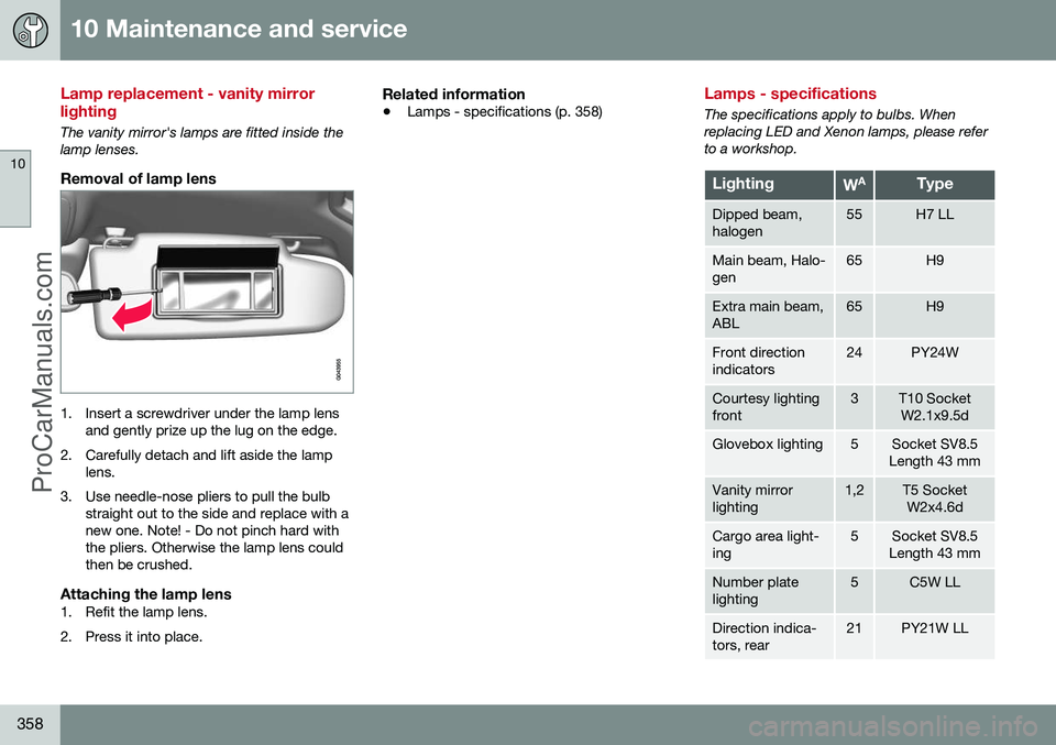
Removal of lamp lens
1. Insert a screwdriver under the lamp lensand gently prize up the lug on the edge.
2. Carefully detach and lift aside the lamp lens.
3. Use needle-nose pliers to pull the bulb straight out to the side and replace with a new one. Note! - Do not pinch hard withthe pliers. Otherwise the lamp lens couldthen be crushed.
Attaching the lamp lens1. Refit the lamp lens.
2. Press it into place.
Related information
• Lamps - specifications (p. 358)
Lamps - specifications
The specifications apply to bulbs. When replacing LED and Xenon lamps, please referto a workshop.
LightingWAType
Dipped beam, halogen55H7 LL
Main beam, Halo- gen65H9
Extra main beam, ABL65H9
Front direction indicators24PY24W
Courtesy lighting front3T10 Socket
W2.1x9.5d
Glovebox lighting5Socket SV8.5
Length 43 mm
Vanity mirror lighting1,2T5 Socket W2x4.6d
Cargo area light- ing5Socket SV8.5
Length 43 mm
Number plate lighting5C5W LL
Direction indica- tors, rear21PY21W LL
ProCarManuals.co’
Page 369 of 442
10 Maintenance and service
10
367
Fuses - general
All electrical functions and components are protected by a number of fuses in order toprotect the car's electrical system from dam-age by short circuiting or overloading. If an electrical component or function does not work, it may be because the component'sfuse was temporarily overloaded and failed. Ifthe same fuse fails repeatedly then there is afault in the circuit. Volvo recommends thatyou visit an authorised Volvo workshop forchecking.
Changing1. Look in the fuse diagram to locate thefuse.
2. Pull out the fuse and check from the side to see whether the curved wire hasblown.
3. If this is the case, replace it with a new fuse of the same colour and amperage.
WARNING
Never use a foreign object or a fuse with an amperage higher than that specifiedwhen replacing a fuse. This could causesignificant damage to the electrical systemand possibly lead to fire.
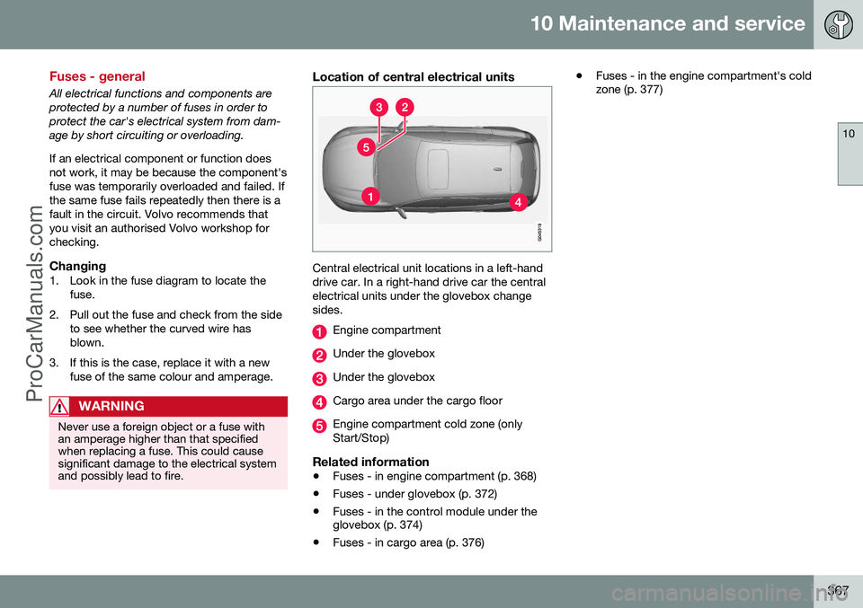
Location of central electrical units
Central electrical unit locations in a left-hand drive car. In a right-hand drive car the centralelectrical units under the glovebox changesides.
Engine compartment
Under the glovebox
Under the glovebox
Cargo area under the cargo floor
Engine compartment cold zone (only Start/Stop)
Related information
• Fuses - in engine compartment (p. 368)
• Fuses - under glovebox (p. 372)
• Fuses - in the control module under the glovebox (p. 374)
• Fuses - in cargo area (p. 376) •
Fuses - in the engine compartment's coldzone (p. 377)
ProCarManuals.co’
Page 371 of 442
10 Maintenance and service
10
}}
* Option/accessory, for more information, see Introduction.369
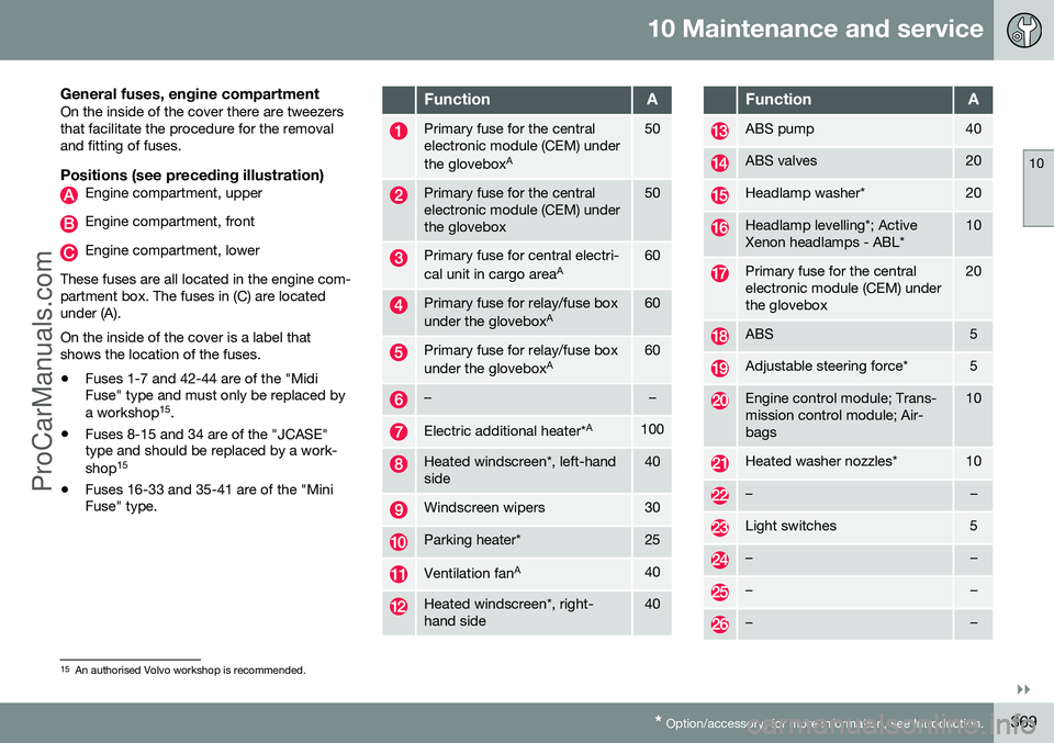
General fuses, engine compartmentOn the inside of the cover there are tweezers that facilitate the procedure for the removaland fitting of fuses.
Positions (see preceding illustration)Engine compartment, upper
Engine compartment, front
Engine compartment, lower
These fuses are all located in the engine com- partment box. The fuses in (C) are locatedunder (A). On the inside of the cover is a label that shows the location of the fuses. • Fuses 1-7 and 42-44 are of the "Midi Fuse" type and must only be replaced by a workshop 15
.
• Fuses 8-15 and 34 are of the "JCASE" type and should be replaced by a work- shop 15
• Fuses 16-33 and 35-41 are of the "Mini Fuse" type.
FunctionA
Primary fuse for the central electronic module (CEM) under the glovebox A50
Primary fuse for the central electronic module (CEM) underthe glovebox50
Primary fuse for central electri- cal unit in cargo area
A60
Primary fuse for relay/fuse box under the gloveboxA60
Primary fuse for relay/fuse box under the gloveboxA60
––
Electric additional heater* A100
Heated windscreen*, left-hand side40
Windscreen wipers30
Parking heater*25
Ventilation fanA40
Heated windscreen*, right- hand side40
FunctionA
ABS pump40
ABS valves20
Headlamp washer*20
Headlamp levelling*; Active Xenon headlamps - ABL*10
Primary fuse for the central electronic module (CEM) underthe glovebox20
ABS5
Adjustable steering force*5
Engine control module; Trans- mission control module; Air-bags10
Heated washer nozzles*10
––
Light switches5
––
––
––
15
An authorised Volvo workshop is recommended.
ProCarManuals.co’
Page 373 of 442
10 Maintenance and service
10
371
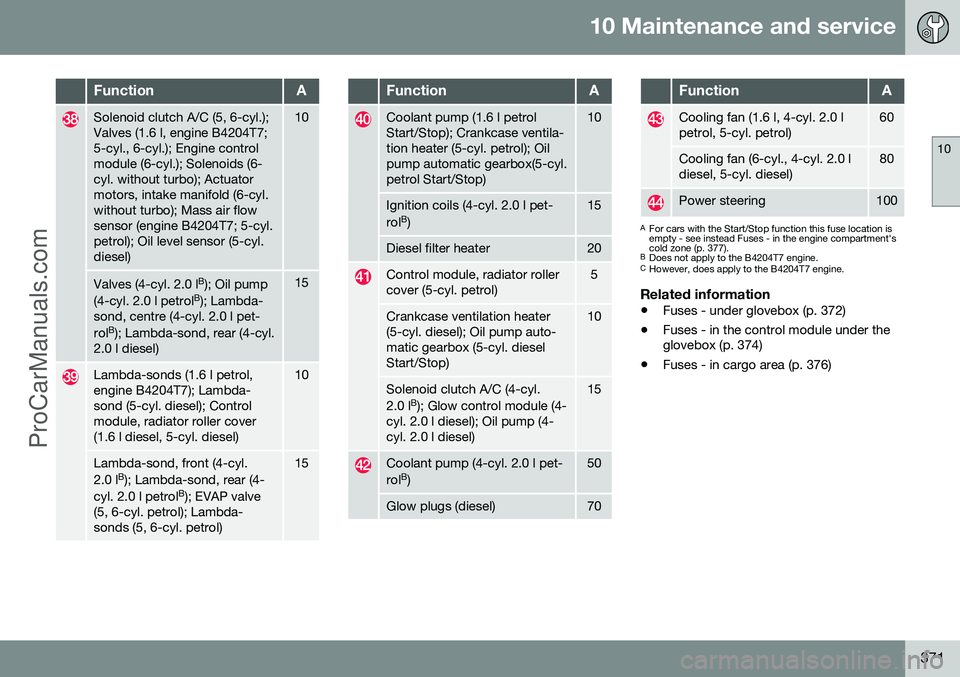
FunctionA
Solenoid clutch A/C (5, 6-cyl.); Valves (1.6 l, engine B4204T7;5-cyl., 6-cyl.); Engine controlmodule (6-cyl.); Solenoids (6-cyl. without turbo); Actuatormotors, intake manifold (6-cyl.without turbo); Mass air flowsensor (engine B4204T7; 5-cyl.petrol); Oil level sensor (5-cyl.diesel)10
Valves (4-cyl. 2.0 lB
); Oil pump
(4-cyl. 2.0 l petrol B
); Lambda-
sond, centre (4-cyl. 2.0 l pet- rol B
); Lambda-sond, rear (4-cyl.
2.0 l diesel)15
Lambda-sonds (1.6 l petrol, engine B4204T7); Lambda-sond (5-cyl. diesel); Controlmodule, radiator roller cover(1.6 l diesel, 5-cyl. diesel)10
Lambda-sond, front (4-cyl. 2.0 l B
); Lambda-sond, rear (4-
cyl. 2.0 l petrol B
); EVAP valve
(5, 6-cyl. petrol); Lambda- sonds (5, 6-cyl. petrol)15
FunctionA
Coolant pump (1.6 l petrol Start/Stop); Crankcase ventila-tion heater (5-cyl. petrol); Oilpump automatic gearbox(5-cyl.petrol Start/Stop)10
Ignition coils (4-cyl. 2.0 l pet- rol B
)15
Diesel filter heater20
Control module, radiator roller cover (5-cyl. petrol)5
Crankcase ventilation heater (5-cyl. diesel); Oil pump auto-matic gearbox (5-cyl. dieselStart/Stop)10
Solenoid clutch A/C (4-cyl. 2.0 l B
); Glow control module (4-
cyl. 2.0 l diesel); Oil pump (4- cyl. 2.0 l diesel)15
Coolant pump (4-cyl. 2.0 l pet- rol B
)50
Glow plugs (diesel)70
FunctionA
Cooling fan (1.6 l, 4-cyl. 2.0 l petrol, 5-cyl. petrol)60
Cooling fan (6-cyl., 4-cyl. 2.0 l diesel, 5-cyl. diesel)80
Power steering100
A For cars with the Start/Stop function this fuse location is empty - see instead Fuses - in the engine compartment'scold zone (p. 377).
B Does not apply to the B4204T7 engine.
C However, does apply to the B4204T7 engine.
Related information
• Fuses - under glovebox (p. 372)
• Fuses - in the control module under the glovebox (p. 374)
• Fuses - in cargo area (p. 376)
ProCarManuals.co’