mirror VOLVO V60 2014 User Guide
[x] Cancel search | Manufacturer: VOLVO, Model Year: 2014, Model line: V60, Model: VOLVO V60 2014Pages: 442, PDF Size: 13.85 MB
Page 99 of 442
03 Instruments and controls
03
* Option/accessory, for more information, see Introduction.97
Automatic dimming*Bright light from behind is automatically dimmed by the rearview mirror. The controlfor manual dimming is not available on mir-rors with automatic dimming. The rearview mirror contains two sensors - one forward facing and one rearward facing -that work together to identify and eliminatedazzling light. The forward facing sensordetects ambient light, while the rearward fac-ing sensor detects the light from vehicleheadlights behind.
NOTE
If the sensors are obscured by e.g. parking permits, transponders, sun visors orobjects in the seats or in the cargo area insuch a way that light is prevented fromreaching the sensors, then the dimmingfunction of the interior rearview and doormirrors is reduced.
The compass (p. 97) can only be specified for a rearview mirror with automatic dimming.
Related information
• Door mirrors (p. 94)
Compass*
The rearview mirror contains an integrated display that shows the compass direction inwhich the front of the car is pointing.
Operation
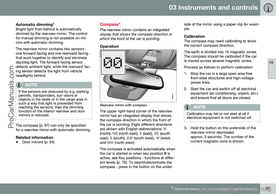
Rearview mirror with compass.
The upper right-hand corner of the rearview mirror has an integrated display that showsthe compass direction in which the front ofthe car is pointing. Eight different directions are shown with English abbreviations:
N(north), NE (north east), E (east), SE (south
east), S (south), SW (south west), W (west)
and NW (north west).
The compass is activated automatically when the car is started or when key position II is
active, see Key positions - functions at differ-ent levels (p. 70). To deactivate/activate thecompass - press in the button on the under- side of the mirror using a paper clip for exam-ple.
CalibrationThe compass may need calibrating to showthe correct compass direction. The earth is divided into 15 magnetic zones. The compass should be calibrated if the caris moved across several magnetic zones. Proceed as follows to perform calibration:
1. Stop the car in a large open area free
from steel structures and high-voltage power lines.
2. Start the car and switch off all electrical equipment (air conditioning, wipers, etc.)and ensure that all doors are closed.
NOTE
Calibration may fail or not start at all if electrical equipment is not switched off.
3. Hold the button on the underside of therearview mirror depressed approx. 3 seconds. The number of thecurrent magnetic zone is shown.
ProCarManuals.co’
Page 100 of 442
03 Instruments and controls
03
98* Option/accessory, for more information, see Introduction.
G030295
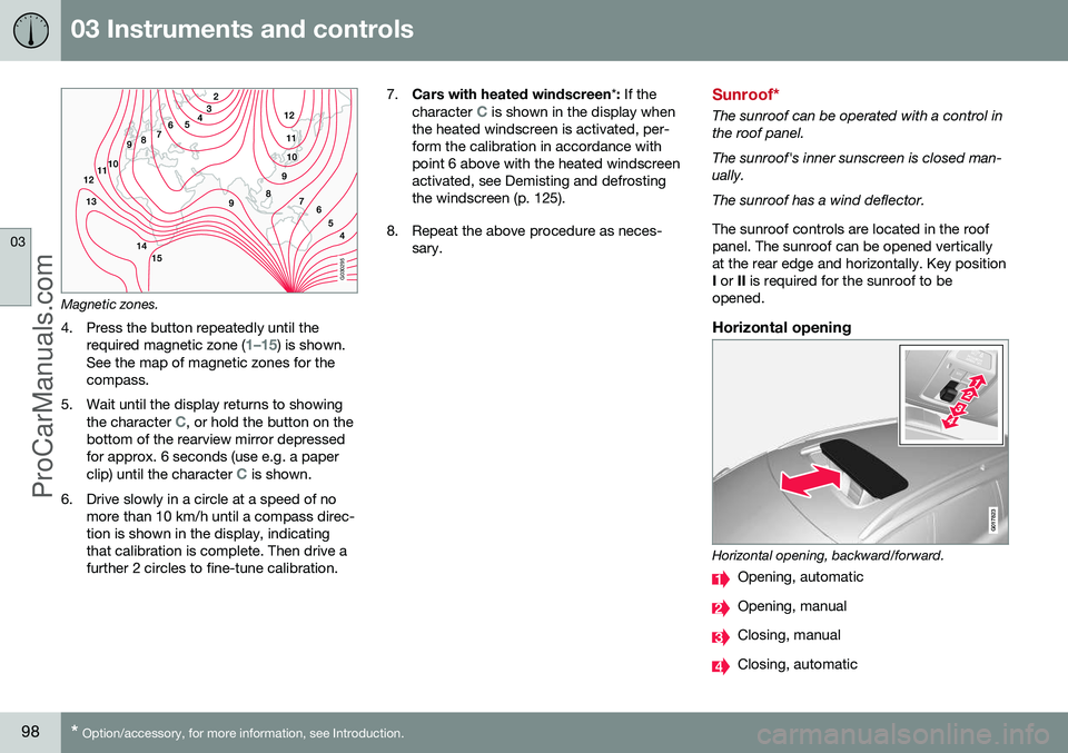
Magnetic zones.
4. Press the button repeatedly until the required magnetic zone (
1–15) is shown.
See the map of magnetic zones for the compass.
5. Wait until the display returns to showing the character
C, or hold the button on the
bottom of the rearview mirror depressed for approx. 6 seconds (use e.g. a paper clip) until the character
C is shown.
6. Drive slowly in a circle at a speed of no more than 10 km/h until a compass direc- tion is shown in the display, indicatingthat calibration is complete. Then drive afurther 2 circles to fine-tune calibration. 7.
Cars with heated windscreen *: If the
character
C is shown in the display when
the heated windscreen is activated, per- form the calibration in accordance withpoint 6 above with the heated windscreenactivated, see Demisting and defrostingthe windscreen (p. 125).
8. Repeat the above procedure as neces- sary.Sunroof*
The sunroof can be operated with a control in the roof panel. The sunroof's inner sunscreen is closed man- ually. The sunroof has a wind deflector. The sunroof controls are located in the roof panel. The sunroof can be opened verticallyat the rear edge and horizontally. Key positionI or II is required for the sunroof to be
opened.
Horizontal opening
G017823
Horizontal opening, backward/forward.
Opening, automatic
Opening, manual
Closing, manual
Closing, automatic
ProCarManuals.co’
Page 118 of 442
04 Climate control
04
116* Option/accessory, for more information, see Introduction.
Actual temperature
The temperature you select in the passenger compartment corresponds to the physicalexperience with reference to factors such asair speed, humidity and solar radiation etc. inand around the car. The system includes a sun sensor (p. 116) which detects on which side the sun is shin-ing into the passenger compartment. Thismeans that the temperature can differbetween the right and left-hand air ventsdespite the controls being set for the sametemperature on both sides.
Related information
• General information on climate control (p. 115)
• Temperature control in the passengercompartment (p. 124)
Sensors - climate control
The climate control system has a number of sensors to help control the temperature (p.116) in the car.
• The sun sensor is located on the top side of the dashboard.
• The temperature sensor for the passen-ger compartment is located below the cli-mate control panel.
• The outside temperature sensor islocated in the door mirror.
• The humidity sensor* is located by theinterior rearview mirror.
NOTE
Do not cover or block the sensors with clothing or other objects.
Related information
•General information on climate control (p. 115)
Air cleaning
The interior in a passenger compartment is designed to be pleasant and comfortable,even for people with contact allergies and forasthma sufferers.
• Passenger compartment filter (p. 117)
• Material in the passenger compart- ment (p. 118)
• Clean Zone Interior Package (CZIP) (p.117)*
• Interior Air Quality System (IAQS) (p.118)*
Related information
• General information on climate control (p.115)
ProCarManuals.co’
Page 123 of 442
04 Climate control
04
121
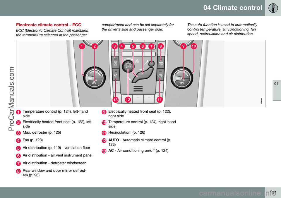
Electronic climate control - ECC
ECC (Electronic Climate Control) maintains the temperature selected in the passengercompartment and can be set separately forthe driver's side and passenger side.
The auto function is used to automaticallycontrol temperature, air conditioning, fanspeed, recirculation and air distribution.
Temperature control (p. 124), left-hand side
Electrically heated front seat (p. 122), left side
Max. defroster (p. 125)
Fan (p. 123)
Air distribution (p. 119) - ventilation floor
Air distribution - air vent instrument panel
Air distribution - defroster windscreen
Rear window and door mirror defrost- ers (p. 96)
Electrically heated front seat (p. 122), right side
Temperature control (p. 124), right-hand side
Recirculation (p. 126)
AUTO
- Automatic climate control (p.
123)
AC - Air conditioning on/off (p. 124)
ProCarManuals.co’
Page 127 of 442
04 Climate control
04
* Option/accessory, for more information, see Introduction.125
Demisting and defrosting the windscreen
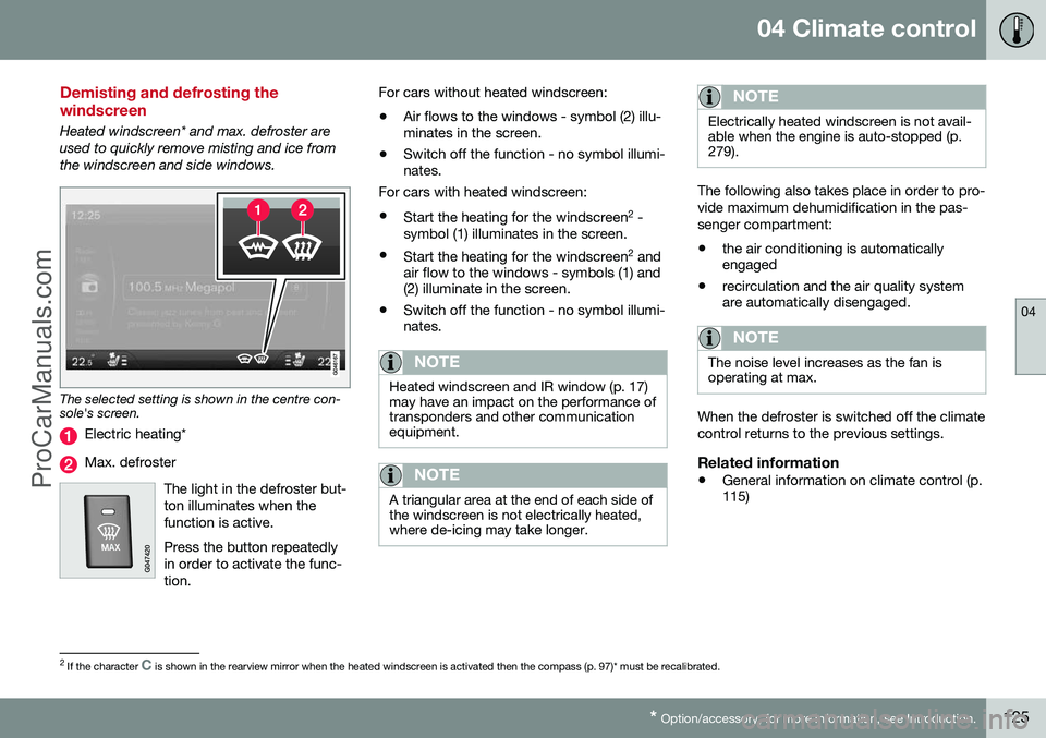
Heated windscreen* and max. defroster are used to quickly remove misting and ice fromthe windscreen and side windows.
The selected setting is shown in the centre con- sole's screen.
Electric heating*
Max. defroster
The light in the defroster but- ton illuminates when thefunction is active. Press the button repeatedly in order to activate the func-tion.
For cars without heated windscreen:• Air flows to the windows - symbol (2) illu- minates in the screen.
• Switch off the function - no symbol illumi-nates.
For cars with heated windscreen:
• Start the heating for the windscreen 2
-
symbol (1) illuminates in the screen.
• Start the heating for the windscreen 2
and
air flow to the windows - symbols (1) and(2) illuminate in the screen.
• Switch off the function - no symbol illumi-nates.
NOTE
Heated windscreen and IR window (p. 17) may have an impact on the performance oftransponders and other communicationequipment.
NOTE
A triangular area at the end of each side of the windscreen is not electrically heated,where de-icing may take longer.
NOTE
Electrically heated windscreen is not avail- able when the engine is auto-stopped (p.279).
The following also takes place in order to pro- vide maximum dehumidification in the pas-senger compartment:
• the air conditioning is automatically engaged
• recirculation and the air quality systemare automatically disengaged.
NOTE
The noise level increases as the fan is operating at max.
When the defroster is switched off the climate control returns to the previous settings.
Related information
• General information on climate control (p. 115)
2
If the character C is shown in the rearview mirror when the heated windscreen is activated then the compass (p. 97)* must be recalibrated.
ProCarManuals.co’
Page 142 of 442
05 Loading and storage
05
140* Option/accessory, for more information, see Introduction.
Glovebox
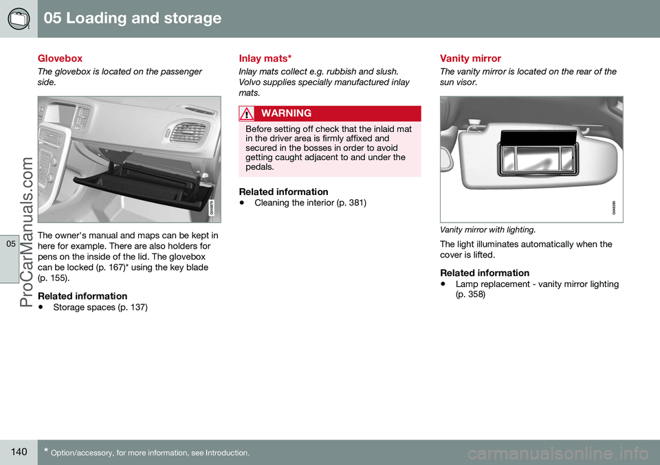
The glovebox is located on the passenger side.
The owner's manual and maps can be kept in here for example. There are also holders forpens on the inside of the lid. The gloveboxcan be locked (p. 167)* using the key blade(p. 155).
Related information
• Storage spaces (p. 137)
Inlay mats*
Inlay mats collect e.g. rubbish and slush. Volvo supplies specially manufactured inlaymats.
WARNING
Before setting off check that the inlaid mat in the driver area is firmly affixed andsecured in the bosses in order to avoidgetting caught adjacent to and under thepedals.
Related information
•Cleaning the interior (p. 381)
Vanity mirror
The vanity mirror is located on the rear of the sun visor.
Vanity mirror with lighting.
The light illuminates automatically when the cover is lifted.
Related information
• Lamp replacement - vanity mirror lighting (p. 358)
ProCarManuals.co’
Page 151 of 442
06 Locks and alarm
06
* Option/accessory, for more information, see Introduction.149
Remote control key with key blade
The remote control key is used to start the car and for locking and unlocking. It contains adetachable key blade (p. 155) made of metal.The visible section is available in two versionsso that it is possible to distinguish betweenthe remote control keys. The car is supplied with 2 remote control keys or PCCs* (Personal Car Communicator). Additional remote control keys can be ordered - up to 6 can be programmed andused for the same car.
WARNING
If there are children in the car: Remember to switch off the supply to the power windows and sunroof by removingthe remote control key if the driver leavesthe car.
Remote control key with PCC (p. 153) has increased functionality compared with theremote control key, see PCC* - unique func-tions (p. 153).
Related information
• Remote control key - functions (p. 151)
Remote control key - losing
If you lose a remote control key then a new one can be ordered at a workshop - anauthorised Volvo workshop is recommended. The remaining remote control keys must be taken to the Volvo workshop. The code of themissing remote control key must be erasedfrom the system as a theft prevention meas-ure. The current number of keys registered tothe car can be checked in the menu systemMY CAR
. For a description of the menu sys-
tem, see MY CAR (p. 103).
Related information
• Remote control key - functions (p. 151)
Key memory*
The key memory in the remote control key (p. 149) means that certain settings in the car canbe individually adapted for different people. The key memory function is available in com- bination with power seat and power rearviewand door mirrors. Settings for door mirrors,driver's seat and steering force can be savedin the key memory.
Key memory – door mirrors and driver's
seat
The settings are automatically connected toeach respective remote control key, see Keymemory* in remote control key (p. 74) andAdjustable steering force* (p. 257). Afterlocking with the remote control key the set-ting of the combined instrument panel'stheme is also saved in the key, see MY CAR(p. 103). The function can be activated/deactivated in the menu system MY CAR. For a description
of the menu system, see MY CAR (p. 103). For cars with the Keyless drive function, see Keyless drive* (p. 159).
ProCarManuals.co’
Page 152 of 442
06 Locks and alarm
06
150* Option/accessory, for more information, see Introduction.
Indication locking/unlocking - adjusting
When the car is locked or unlocked using the remote control key (p. 149) the direction indi-cators confirm that locking/unlocking wascorrectly performed.
• Locking - one flash and the door mirrors are folded 1
in.
• Unlocking - two flashes and the door mir-rors are folded 1
out.
After locking the indication is only given if all locks are activated once the doors have beenclosed.
Selecting the functionDifferent options for indicating locking/unlocking with light can be set in the car'smenu system MY CAR. For a description of
the menu system, see MY CAR (p. 103).
Related information
• Keyless drive* (p. 159)
• Lock indicator (p. 150)
• Alarm indicator (p. 172)
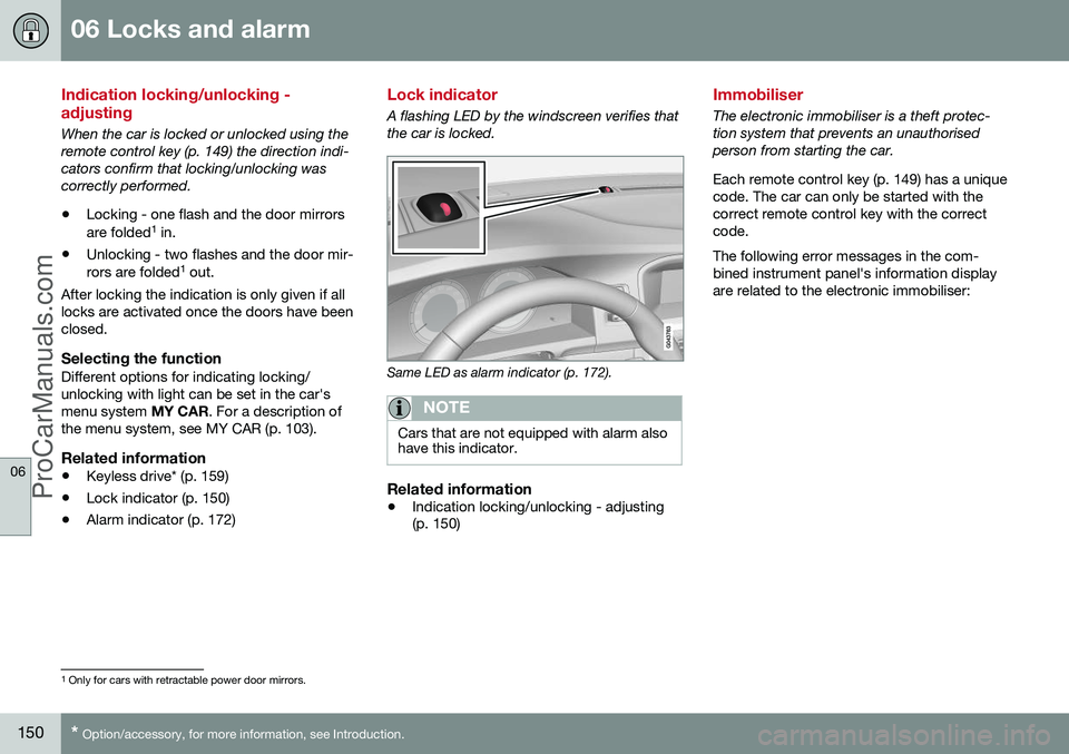
Lock indicator
A flashing LED by the windscreen verifies that the car is locked.
Same LED as alarm indicator (p. 172).
NOTE
Cars that are not equipped with alarm also have this indicator.
Related information
•Indication locking/unlocking - adjusting (p. 150)
Immobiliser
The electronic immobiliser is a theft protec- tion system that prevents an unauthorisedperson from starting the car. Each remote control key (p. 149) has a unique code. The car can only be started with thecorrect remote control key with the correctcode. The following error messages in the com- bined instrument panel's information displayare related to the electronic immobiliser:
1
Only for cars with retractable power door mirrors.
ProCarManuals.co’
Page 164 of 442
06 Locks and alarm
06
162* Option/accessory, for more information, see Introduction.
Keyless drive* - unlocking with the key blade
If central locking cannot be unlocked with the PCC, e.g. if the batteries are discharged, thenthe left-hand front door can be opened withthe PCC's detachable key blade (see Detach-able key blade - detaching/attaching (p. 155)).
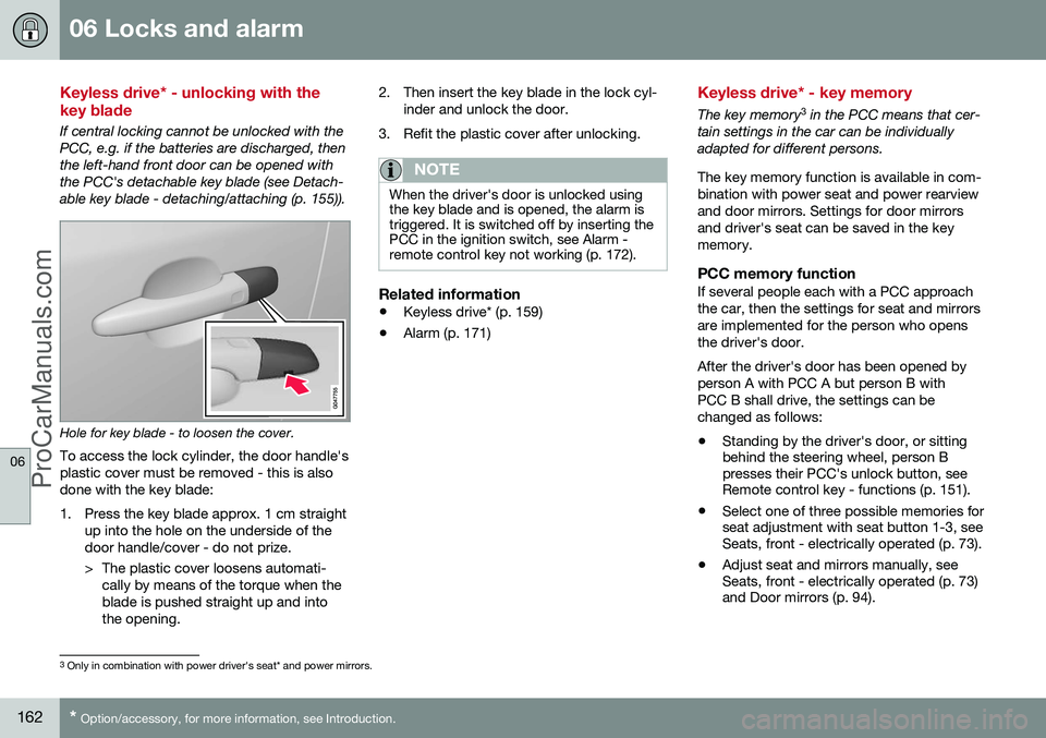
Hole for key blade - to loosen the cover.
To access the lock cylinder, the door handle's plastic cover must be removed - this is alsodone with the key blade:
1. Press the key blade approx. 1 cm straight up into the hole on the underside of the door handle/cover - do not prize.
> The plastic cover loosens automati-cally by means of the torque when the blade is pushed straight up and intothe opening. 2. Then insert the key blade in the lock cyl-
inder and unlock the door.
3. Refit the plastic cover after unlocking.
NOTE
When the driver's door is unlocked using the key blade and is opened, the alarm istriggered. It is switched off by inserting thePCC in the ignition switch, see Alarm -remote control key not working (p. 172).
Related information
• Keyless drive* (p. 159)
• Alarm (p. 171)
Keyless drive* - key memory
The key memory 3
in the PCC means that cer-
tain settings in the car can be individually adapted for different persons. The key memory function is available in com- bination with power seat and power rearviewand door mirrors. Settings for door mirrorsand driver's seat can be saved in the keymemory.
PCC memory functionIf several people each with a PCC approachthe car, then the settings for seat and mirrorsare implemented for the person who opensthe driver's door. After the driver's door has been opened by person A with PCC A but person B withPCC B shall drive, the settings can bechanged as follows:
• Standing by the driver's door, or sitting behind the steering wheel, person Bpresses their PCC's unlock button, seeRemote control key - functions (p. 151).
• Select one of three possible memories forseat adjustment with seat button 1-3, seeSeats, front - electrically operated (p. 73).
• Adjust seat and mirrors manually, seeSeats, front - electrically operated (p. 73)and Door mirrors (p. 94).
3
Only in combination with power driver's seat* and power mirrors.
ProCarManuals.co’
Page 247 of 442
07 Driver support
07
}}
245
Light conditionsThe camera image is adjusted automatically according to prevailing light conditions.Because of this, the image may vary slightlyin brightness and quality. Poor light condi-tions can result in a slightly reduced imagequality.
NOTE
Keep the camera lens clear of dirt, snow and ice to ensure optimum function. Thisis particularly important in poor light.
Park assist lines
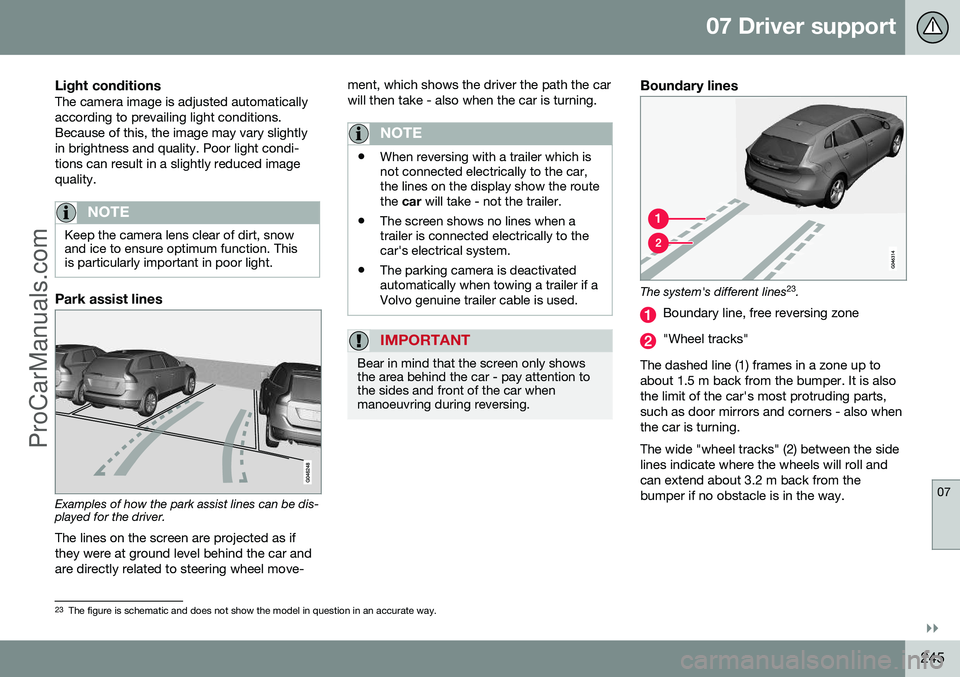
Examples of how the park assist lines can be dis- played for the driver.The lines on the screen are projected as if they were at ground level behind the car andare directly related to steering wheel move- ment, which shows the driver the path the carwill then take - also when the car is turning.
NOTE
•
When reversing with a trailer which is not connected electrically to the car,the lines on the display show the routethe
car will take - not the trailer.
• The screen shows no lines when atrailer is connected electrically to thecar's electrical system.
• The parking camera is deactivatedautomatically when towing a trailer if aVolvo genuine trailer cable is used.
IMPORTANT
Bear in mind that the screen only shows the area behind the car - pay attention tothe sides and front of the car whenmanoeuvring during reversing.
Boundary lines
The system's different lines 23
.
Boundary line, free reversing zone
"Wheel tracks"
The dashed line (1) frames in a zone up to about 1.5 m back from the bumper. It is alsothe limit of the car's most protruding parts,such as door mirrors and corners - also whenthe car is turning. The wide "wheel tracks" (2) between the side lines indicate where the wheels will roll andcan extend about 3.2 m back from thebumper if no obstacle is in the way.
23 The figure is schematic and does not show the model in question in an accurate way.
ProCarManuals.co’