VOLVO V60 2015 Owner´s Manual
Manufacturer: VOLVO, Model Year: 2015, Model line: V60, Model: VOLVO V60 2015Pages: 414, PDF Size: 11.44 MB
Page 301 of 414
07 During your trip
Refueling
07
}}
299
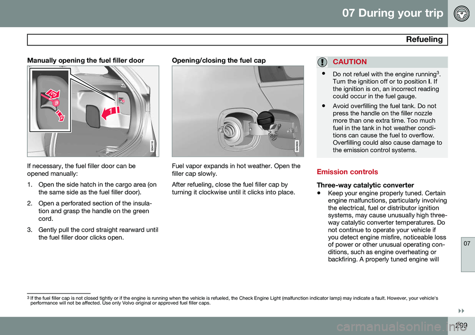
Manually opening the fuel filler door
If necessary, the fuel filler door can be opened manually:
1. Open the side hatch in the cargo area (onthe same side as the fuel filler door).
2. Open a perforated section of the insula- tion and grasp the handle on the green cord.
3. Gently pull the cord straight rearward until the fuel filler door clicks open.
Opening/closing the fuel cap
Fuel vapor expands in hot weather. Open the filler cap slowly. After refueling, close the fuel filler cap by turning it clockwise until it clicks into place.
CAUTION
•Do not refuel with the engine running 3
.
Turn the ignition off or to position I. If
the ignition is on, an incorrect reading could occur in the fuel gauge.
• Avoid overfilling the fuel tank. Do notpress the handle on the filler nozzlemore than one extra time. Too muchfuel in the tank in hot weather condi-tions can cause the fuel to overflow.Overfilling could also cause damage tothe emission control systems.
Emission controls
Three-way catalytic converter
•
Keep your engine properly tuned. Certain engine malfunctions, particularly involvingthe electrical, fuel or distributor ignitionsystems, may cause unusually high three-way catalytic converter temperatures. Donot continue to operate your vehicle ifyou detect engine misfire, noticeable lossof power or other unusual operating con-ditions, such as engine overheating orbackfiring. A properly tuned engine will
3
If the fuel filler cap is not closed tightly or if the engine is running when the vehicle is refueled, the Check Engine Light (malfunction indicator lamp) may indicate a fault. However, your vehicle's performance will not be affected. Use only Volvo original or approved fuel filler caps.
Page 302 of 414
07 During your trip
Refueling
07
300
help avoid malfunctions that could dam- age the three-way catalytic converter.
• Do not park your vehicle over combusti-ble materials, such as grass or leaves,which can come into contact with the hotexhaust system and cause such materialsto ignite under certain wind and weatherconditions.
• Excessive starter cranking (in excess ofone minute), or an intermittently firing orflooded engine can cause three-way cat-alytic converter or exhaust system over-heating.
• Remember that tampering or unauthor-ized modifications to the engine, theEngine Control Module, or the vehiclemay be illegal and can cause three-waycatalytic converter or exhaust systemoverheating. This includes: altering fuelinjection settings or components, alteringemission system components or locationor removing components, and/or repea-ted use of leaded fuel.
NOTE
Unleaded fuel is required for vehicles with three-way catalytic converters.
Heated oxygen sensorsThe heated oxygen sensors monitor the oxy- gen content of the exhaust gases. Readings are fed into a control module that continu-ously monitors engine functions and controlsfuel injection. The ratio of fuel to air into theengine is continuously adjusted for efficientcombustion to help reduce harmful emis-sions.
Page 303 of 414
07 During your trip
Loading
07
}}
* Option/accessory, for more information, see Introduction.301
Introduction
The load carrying capacity of your vehicle is determined by factors such as the number ofpassengers, the amount of cargo, the weightof any accessories that may be installed, etc. To increase loading space, the rear seat backrests can be folded down, see page 95. When loading the cargo area, keep the fol- lowing in mind:
• Load objects in the cargo area against the backrest whenever possible.
• Unstable loads can be secured to theload anchoring eyelets with straps or weblashings to help keep them from shifting.
• Stop the engine and apply the parkingbrake when loading or unloading longobjects. The gear selector can beknocked out of position by long loads,which could set the vehicle in motion.WARNING
•Stop the engine, put the gear selector in
P, and apply the parking brake
when loading or unloading longobjects.
• The vehicle's driving characteristicsmay change depending on the weightand distribution of the load.
• A 44-pound (20 kg) object produces aforce of 2,200 pounds (1,000 kg) in ahead-on collision at 30 mph (50 km/h).
• The cargo area and rear seat shouldnot be loaded to a level higher than2 in. (5 cm) below the upper edge ofthe rear side windows. Objects placedhigher than this level could impede thefunction of the Inflatable Curtain.
Folding down the rear seat backrests
The rear seat backrests can be folded down for additional loading space, see page 97.
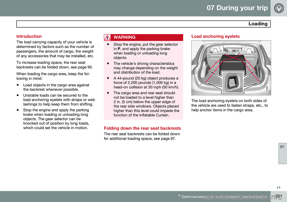
Load anchoring eyelets
The load anchoring eyelets on both sides of the vehicle are used to fasten straps, etc., tohelp anchor items in the cargo area.
Page 304 of 414
07 During your trip
Loading
07
302* Option/accessory, for more information, see Introduction.
WARNING
• Cover sharp edges on long loads to help prevent injury to occupants.Secure the load to help prevent shift-ing during sudden stops.
• Always secure large and heavy objectswith a seat belt or cargo retainingstraps.
• Always secure the load to help preventit from moving in the event of suddenstops.
• Switch off the engine, apply the park-ing brake and put the gear selector inP
when loading and unloading the
vehicle.
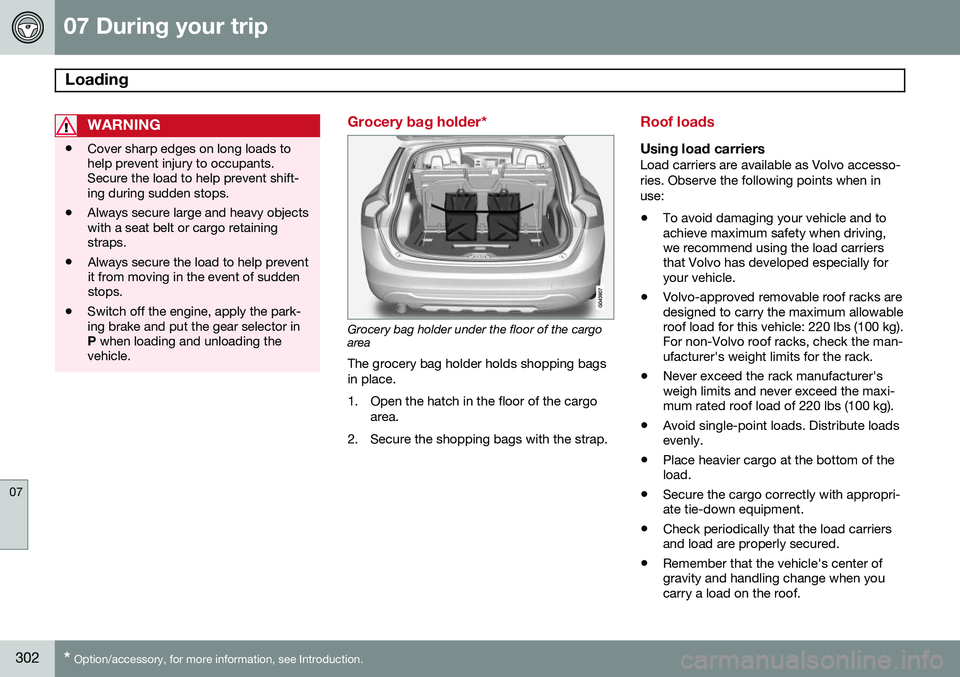
Grocery bag holder*
Grocery bag holder under the floor of the cargo area
The grocery bag holder holds shopping bags in place.
1. Open the hatch in the floor of the cargo area.
2. Secure the shopping bags with the strap.
Roof loads
Using load carriersLoad carriers are available as Volvo accesso- ries. Observe the following points when inuse:
• To avoid damaging your vehicle and to achieve maximum safety when driving,we recommend using the load carriersthat Volvo has developed especially foryour vehicle.
• Volvo-approved removable roof racks aredesigned to carry the maximum allowableroof load for this vehicle: 220 lbs (100 kg).For non-Volvo roof racks, check the man-ufacturer's weight limits for the rack.
• Never exceed the rack manufacturer'sweigh limits and never exceed the maxi-mum rated roof load of 220 lbs (100 kg).
• Avoid single-point loads. Distribute loadsevenly.
• Place heavier cargo at the bottom of theload.
• Secure the cargo correctly with appropri-ate tie-down equipment.
• Check periodically that the load carriersand load are properly secured.
• Remember that the vehicle's center ofgravity and handling change when youcarry a load on the roof.
Page 305 of 414
07 During your trip
Loading
07
303
•
The vehicle's wind resistance and fuel consumption will increase with the size ofthe load.
• Drive smoothly. Avoid rapid starts, fastcornering and hard braking.
Page 306 of 414
07 During your trip
Cargo area
07
304* Option/accessory, for more information, see Introduction.
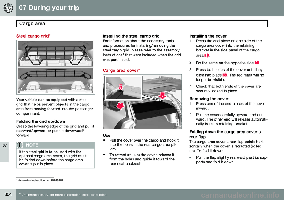
Steel cargo grid*
Your vehicle can be equipped with a steel grid that helps prevent objects in the cargoarea from moving forward into the passengercompartment.
Folding the grid up/downGrasp the lowering edge of the grid and pull itrearward/upward, or push it downward/forward.
NOTE
If the steel grid is to be used with the optional cargo area cover, the grid mustbe folded down before the cargo areacover is put in place.
Installing the steel cargo gridFor information about the necessary tools and procedures for installing/removing thesteel cargo grid, please refer to the assembly instructions 1
that were included when the grid
was purchased.
Cargo area cover*
Use
• Pull the cover over the cargo and hook it into the holes in the rear cargo area pil-lars.
• To retract (roll up) the cover, release itfrom the holes and guide it toward therear seat backrest.
Installing the cover1. Press the end piece on one side of the
cargo area cover into the retaining bracket in the side panel of the cargo area
.
2. Do the same on the opposite side
.
3. Press both sides of the cover until they click into place
. The red mark will no
longer be visible.
4. Check that both ends of the cover are securely locked in place.
Removing the cover1. Press one of the end pieces of the coverinward.
2. Pull the cover carefully upward and out- ward. The other end will release automati- cally from its retaining bracket.
Folding down the cargo area cover's rear flap
The cargo area cover's rear flap points hori- zontally when the cover is retracted (rolledup). To fold it down:
–Pull the flap slightly rearward past its sup- ports and fold it down.
1Assembly instruction no. 30756681.
Page 307 of 414

07 During your trip
Cargo area
07
}}
* Option/accessory, for more information, see Introduction.305
NOTE
On models equipped with this cover, it should be removed before a child seat isattached to the child restraint anchors.
Cargo net*
Storage compartment for the cargo net
Two cassettes containing nylon cargo nets are stored in a compartment under the cargoarea floor.
Attaching the cassette(s)
The two-sections of the net are attached to the rear side of the rear seat backrest. Thecassettes have different widths, and the wid-est section should be mounted on the rightside (seen from the rear of the vehicle).
1. Fold down the rear seat backrests.
2. Align the cassette’s mounting rail above the mounting brackets on the backrest
.
3. Slide the cassette onto the mounting brackets
.
4. Return the backrest to the upright posi- tion.
Using the net(s)
With the backrests uprightThe net is pulled up from the cassette and locks in position after approximately 1minute.
Pull up the right side of the net by grasp- ing its strap.
Insert the net’s rod in the retaining bracket on the right side near the ceilingand press it forward. It will click intoplace.
Extend the left section of the rod and insert it in the bracket on the left side ofthe cargo compartment. Press it forwarduntil it clicks into place.
Page 308 of 414
07 During your trip
Cargo area
07
306
Pull up the left side of the cargo net and secure it on the rod.
NOTE
•The net can be fastened in the same way if the rear seat backrests arefolded down. In this case, use theretaining brackets near the ceiling,above the front seats.
• The front passenger's seat backrestcan also be folded down for carryinglong objects.
Removing the cargo net cassettes1. Retract the net(s) in the reverse order.
2. Fold the entire rear seat backrest down.
3. Slide the cassettes outward until they
release from the mounting brackets.
WARNING
•When not in use, return the cassettes to their storage compartment underthe cargo area floor.
• Objects in the cargo area should besecurely anchored, even if the cargonet is correctly installed and in use.
Using the cargo net with the cargo area cover
G018247
Straps for pulling up the net
The cargo net(s) can also be pulled up from the backrest when the cargo area cover ispulled out. The straps for pulling up the cargo net are located at the arrows in the illustration. Followthe same procedure as for using the nets withthe backrests upright.
Page 309 of 414
07 During your trip
Towing a trailer
07
}}
307
Introduction
Volvo recommends the use of Volvo trailer hitches that are specially designed for thevehicle.
NOTE
See page 391 for the maximum trailer and tongue weights recommended by Volvo.
•Observe the legal requirements of the state/province in which the vehicles are
• All Volvo models are equipped withenergy-absorbing shock-mounted bump-ers. Trailer hitch installation should notinterfere with the proper operation of thisbumper system.
Trailer towing does not normally present any particular problems, but take into considera-tion: • Increase tire pressure to recommended full pressure. See the tire inflation tableon page 320.
• When your vehicle is new, avoid towingheavy trailers during the first 620 miles(1,000 km).
• Maximum speed when towing a trailer:50 mph (80 km/h).
• Engine and transmission are subject toincreased loads. Therefore, engine cool-ant temperature should be closely watched when driving in hot climates orhilly terrain. Use a lower gear and turn offthe air conditioner if the temperaturegauge needle enters the red range.
• If the automatic transmission begins tooverheat, a message will be displayed inthe text window.
• Avoid overload and other abusive opera-tion.
• Hauling a trailer affects handling, durabil-ity, and economy.
• It is necessary to balance trailer brakeswith the towing vehicle brakes to providea safe stop (check and observe state/local regulations).
• Do not connect the trailer's brake systemdirectly to the vehicle's brake system.
• More frequent vehicle maintenance isrequired.
• Remove the ball holder when the hitch isnot being used.
WARNING
• Bumper-attached trailer hitches must not be used on Volvos, nor shouldsafety chains be attached to thebumper.
• Trailer hitches attaching to the vehiclerear axle must not be used.
• Never connect a trailer's hydraulicbrake system directly to the vehiclebrake system, nor a trailer's lightingsystem directly to the vehicle lightingsystem. Consult your nearest author-ized Volvo retailer for correct installa-tion.
• When towing a trailer, the trailer'ssafety wire must be correctly fastenedto the hole or hook provided in thetrailer hitch on the vehicle. The safetywire should never be fastened to orwound around the drawbar ball.
Page 310 of 414
07 During your trip
Towing a trailer
07
308
NOTE
•When parking the vehicle with a trailer on a hill, apply the parking brakebefore putting the gear selector in
P.
Always follow the trailer manufactur-er's recommendations for wheelchocking.
• When starting on a hill, put the gearselector in
D before releasing the park-
ing brake.
• If you use the manual (Geartronic) shiftpositions while towing a trailer, makesure the gear you select does not puttoo much strain on the engine (usingtoo high a gear).
• The drawbar assembly/trailer hitchmay be rated for trailers heavier thanthe vehicle is designed to tow. Pleaseadhere to Volvo's recommended trailerweights.
• Avoid driving with a trailer on inclinesof more than 15%.
Trailer cableAn adapter is required if the vehicle's trailer hitch has a 13-pin connector and the trailerhas 7 pins. Use an adapter cable approvedby Volvo. Make sure the cable does not dragon the ground.
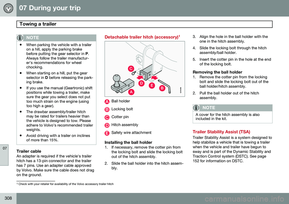
Detachable trailer hitch (accessory) 1
A
C
EDBG010496
Ball holder
Locking bolt
Cotter pin
Hitch assembly
Safety wire attachment
Installing the ball holder1. If necessary, remove the cotter pin from
the locking bolt and slide the locking bolt out of the hitch assembly.
2. Slide the ball holder into the hitch assem- bly. 3. Align the hole in the ball holder with the
one in the hitch assembly.
4. Slide the locking bolt through the hitch assembly/ball holder.
5. Insert the cotter pin in the hole at the end of the locking bolt.
Removing the ball holder1. Remove the cotter pin from the lockingbolt and slide the locking bolt out of theball holder/hitch assembly.
2. Pull the ball holder out of the hitch assembly.
NOTE
A cover for the hitch assembly is also included in the kit.
Trailer Stability Assist (TSA)
Trailer Stability Assist is a system designed to help stabilize a vehicle that is towing a trailerwhen the vehicle and trailer have begun tosway and is part of the Dynamic Stability andTraction Control system (DSTC). See page152 for information on DSTC.
1Check with your retailer for availability of the Volvo accessory trailer hitch