VOLVO V60 2017 Owner´s Manual
Manufacturer: VOLVO, Model Year: 2017, Model line: V60, Model: VOLVO V60 2017Pages: 406, PDF Size: 9.65 MB
Page 341 of 406
MAINTENANCE AND SERVICING
}}
339
Engine compartment – engine oil
The correct oil must be used for the stated oil change (service) intervals to apply. The oil level on 4-cylinder engines is checked electronically and is checked using a dipstick on5- and 6-cylinder engines.
Checking the engine oil (5- and 6-
cylinder engines)
The oil level should be checked at regular inter- vals, particularly during the period up to the firstscheduled maintenance service.
• See Oil specifications (p. 384) for oil specifi-cations.
• Also, refer to the Warranty and ServiceRecords information booklet for informationon oil change intervals and oil specifications.
CAUTION
•
Not checking the oil level regularly can result in serious engine damage if the oillevel becomes too low.
• Oil that is lower than the specified qualitycan damage the engine.
• Volvo does not recommend the use of oiladditives.
• Always add oil of the same type and vis-cosity as already used.
• Never fill oil above the
MAX mark. This
could cause an increase in oil consump-tion.
• Oil changes should be carried out by atrained and qualified Volvo service techni-cian.
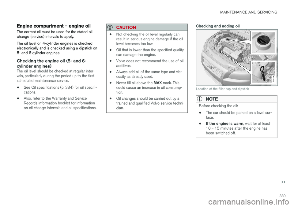
Checking and adding oil
G021734
Location of the filler cap and dipstick
NOTE
Before checking the oil:
• The car should be parked on a level sur- face.
• If the engine is warm
, wait for at least
10 – 15 minutes after the engine hasbeen switched off.
Page 342 of 406
||
MAINTENANCE AND SERVICING
* Option/accessory, for more information, see Introduction.
340
G021737
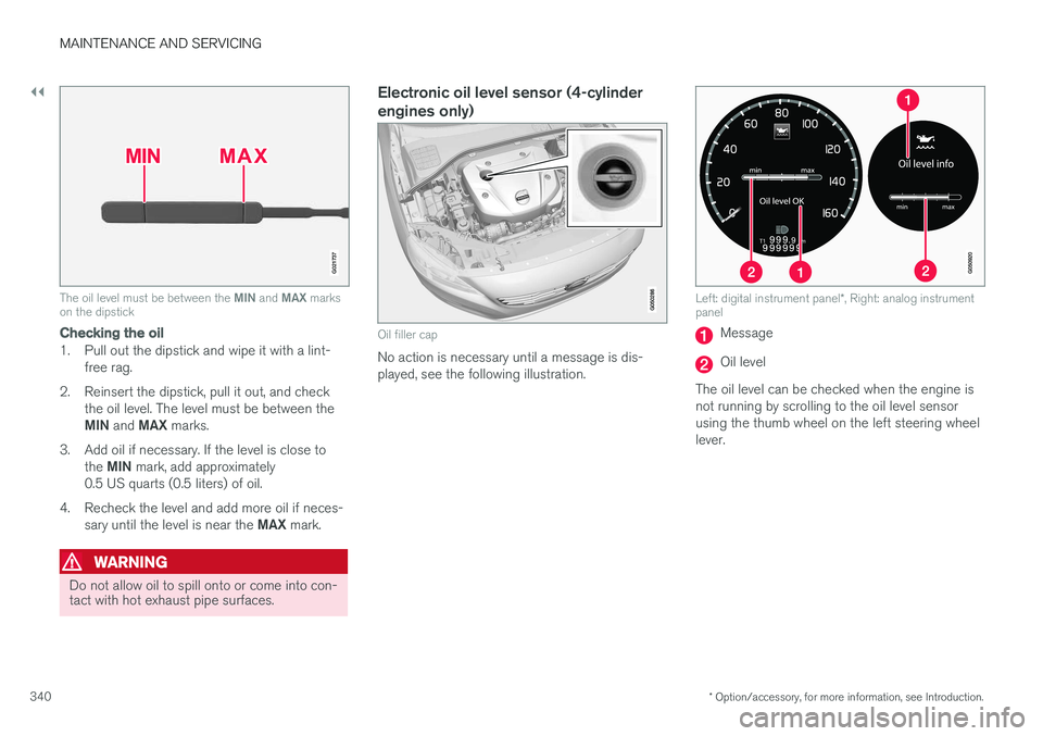
The oil level must be between the MIN and MAX marks
on the dipstick
Checking the oil
1. Pull out the dipstick and wipe it with a lint-
free rag.
2. Reinsert the dipstick, pull it out, and check the oil level. The level must be between the MIN and MAX marks.
3. Add oil if necessary. If the level is close to the MIN mark, add approximately
0.5 US quarts (0.5 liters) of oil.
4. Recheck the level and add more oil if neces- sary until the level is near the MAX mark.
WARNING
Do not allow oil to spill onto or come into con- tact with hot exhaust pipe surfaces.
Electronic oil level sensor (4-cylinder engines only)
Oil filler cap
No action is necessary until a message is dis- played, see the following illustration.
Left: digital instrument panel *, Right: analog instrument
panel
Message
Oil level
The oil level can be checked when the engine is not running by scrolling to the oil level sensorusing the thumb wheel on the left steering wheellever.
Page 343 of 406
MAINTENANCE AND SERVICING
}}
341
CAUTION
•If Oil service required is displayed, the
oil level may be too high. Take the vehicle to an authorized Volvo workshop as soonas possible.
• If the oil level sensor indicates that thelevel is too low, using the correct oil, topup with the amount of oil indicated assoon as possible, see oil specifica-tions (p. 384).
WARNING
Do not allow oil to spill onto or come into con- tact with hot exhaust pipe surfaces.
Electronically checking the oil level
The oil level should be checked at regular inter- vals, particularly during the period up to the firstscheduled maintenance service. To check the oil level:1.
Activate ignition mode II, see Ignition modes
(p. 80).
2. Turn the thumb wheel on the left steering wheel lever until
Oil level is displayed.
> The oil level will be displayed.
NOTE
• The system cannot detect changes in the oil level immediately. The vehicle must bedriven approximately 20 miles (30 km) orhave been parked on level ground withthe engine off for 5 minutes before theoil level reading will be correct.
• If the necessary conditions are not metfor checking the oil level electronically(time interval after the engine wasswitched off, if the vehicle is parked on an incline, etc.),
No values available will
be displayed. This does not indicate a
problem with the oil level sensor.
Engine compartment – coolant
Normally, the coolant does not need to be changed. If the system must be drained, consulta trained and qualified Volvo service technician.
Level check and filling
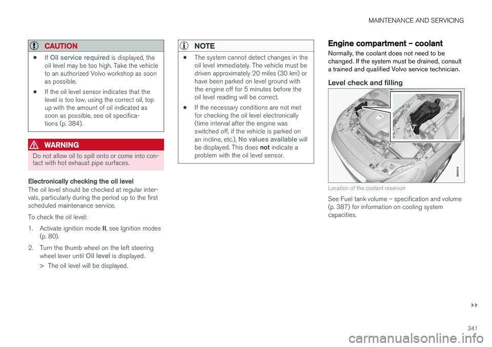
Location of the coolant reservoir
See Fuel tank volume – specification and volume (p. 387) for information on cooling systemcapacities.
Page 344 of 406
MAINTENANCE AND SERVICING
342
CAUTION
•If necessary, top up the cooling system with Volvo Genuine Coolant/Antifreezeonly (a 50/50 mix of water and anti-freeze).
• Different types of antifreeze/coolant maynot be mixed.
• If the cooling system is drained, it shouldbe flushed with clean water or premixedanti-freeze before it is refilled with thecorrect mixture of water/anti-freeze.
• The cooling system must always be keptfilled to the correct level, and the level must be between the
MIN and MAX
marks. If it is not kept filled, there can be high local temperatures in the enginewhich could result in damage. Checkcoolant regularly!
• Do not top up with water only. Thisreduces the rust-protective and anti-freeze qualities of the coolant and has alower boiling point. It can also causedamage to the cooling system if it shouldfreeze.
• Do not use chlorinated tap water in thevehicle's cooling system.
WARNING
•
Never remove the expansion tank cap while the engine is warm. Wait until theengine cools.
• If it is necessary to top off the coolantwhen the engine is warm, unscrew theexpansion tank cap slowly so that theoverpressure dissipates.
Engine compartment – brake fluid
The brake fluid should always be between the MIN and MAX marks on the inside of the reser-
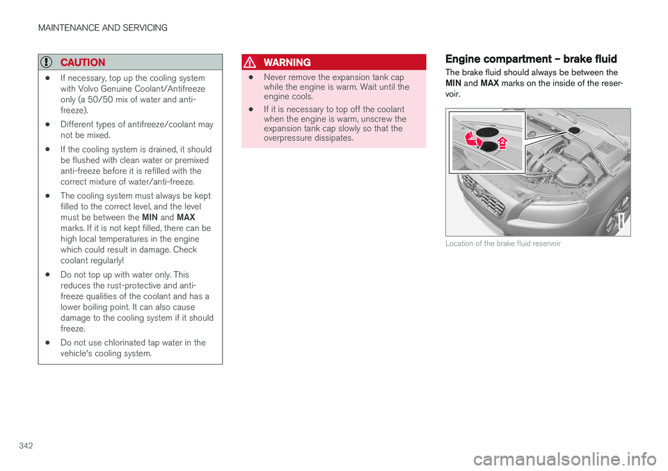
voir.
Location of the brake fluid reservoir
Page 345 of 406
MAINTENANCE AND SERVICING
}}
343
Checking the level
The fluid reservoir is concealed under the round cover at the rear of the engine compartment. Theround cover must be removed first before thereservoir cap can be accessed. Check, without removing the cap, that there is sufficient fluid in the reservoir. Fluid type: DOT 4 boiling point >536 °F
(>280 °C).Replace : The fluid should be replaced according
to the intervals specified in the Warranty and Service Records Information booklet. When driving under extremely hard conditions (mountain driving, etc), it may be necessary toreplace the fluid more often. Consult a trainedand qualified Volvo service technician. Always entrust brake fluid changing to a trained and qualified Volvo service technician.
WARNING
• If the fluid level is below the
MIN mark in
the reservoir or if a brake-related mes- sage is shown in the information display: DO NOT DRIVE . Have the car towed to a
trained and qualified Volvo service techni- cian and have the brake system inspec-ted.
• Dot 4 should never be mixed with anyother type of brake fluid.
Filling
1. Turn and open the cover.
2. Unscrew the reservoir cap and fill the fluid.
The level must be between the MIN and
MAX marks.Engine compartment – power steering fluid
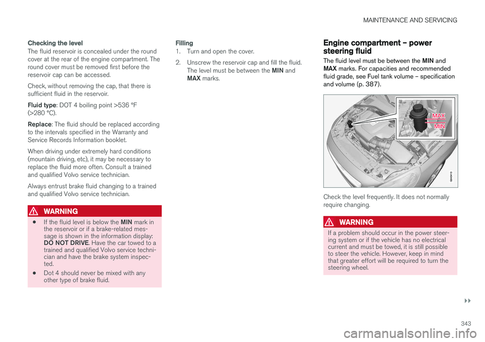
The fluid level must be between the MIN and
MAX marks. For capacities and recommended
fluid grade, see Fuel tank volume – specification and volume (p. 387).
Check the level frequently. It does not normally require changing.
WARNING
If a problem should occur in the power steer- ing system or if the vehicle has no electricalcurrent and must be towed, it is still possibleto steer the vehicle. However, keep in mindthat greater effort will be required to turn thesteering wheel.
Page 346 of 406
MAINTENANCE AND SERVICING
344
CAUTION
Keep the area around the power steering fluid reservoir clean when checking.
Bulbs – introduction
Certain bulbs can be replaced by the vehicle's owner. However, the bulbs on the following listshould only be replaced by a trained and quali-fied Volvo service technician.
All bulb specifications are listed in Bulbs – speci-
fications (p. 351).
• Active Bending Lights
• Front parking lights
• Front side marker lights
• Cornering lights
• Turn signals in the door mirrors
• Approach lighting in the door mirrors
• Interior lighting (except for the front footwelllighting)
• Rear parking lights/side marker lights
• LED bulbs
NOTE
•For information regarding any bulbs not mentioned in this section, please contactyour Volvo retailer or a trained andauthorized Volvo service technician.
• Always switch off the ignition before star-ting to replace a bulb.
• If an error message remains in the dis-play after a faulty bulb has been replaced,contact an authorized Volvo workshop.
• Condensation may form temporarily onthe inside of the lenses of exterior lightssuch as headlights, fog lights, or taillights.This is normal and the lights aredesigned to withstand moisture. Normally,condensation will dissipate after thelights have been on for a short time.
• The optional Active Bending Light bulbscontain trace amounts of mercury. Thesebulbs should always be disposed of by atrained and qualified Volvo service techni-cian.
CAUTION
Never touch the glass of bulbs with your fin- gers. Grease and oils from your fingers vapor-ize in the heat and will leave a deposit on thereflector, which will damage it.
Page 347 of 406
MAINTENANCE AND SERVICING
}}
* Option/accessory, for more information, see Introduction.345
WARNING
•The engine should not be running when changing bulbs.
• If the engine has been running just priorto replacing bulbs in the headlight hous-ing, please keep in mind that componentsin the engine compartment will be hot.
WARNING
•
Active Bending Lights
* – due to the high
voltage used by these headlights, these bulbs should only be replaced by atrained and qualified Volvo service techni-cian.
• Turn off the lights and remove the remotekey from the ignition before changing anybulbs.
Related information
•Bulbs – headlight housing (p. 345)
• Bulbs – taillight housing (p. 349)
• Bulbs – vanity mirror lighting (p. 350)
• Bulbs – cargo area lighting (p. 350)
• Bulbs – license plate lighting (p. 350)
Bulbs – headlight housing
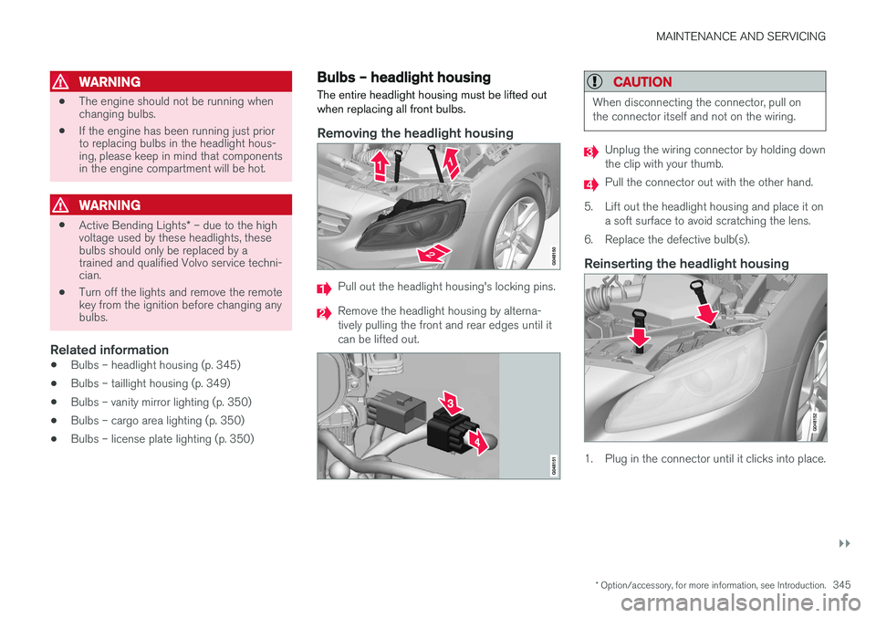
The entire headlight housing must be lifted out when replacing all front bulbs.
Removing the headlight housing
Pull out the headlight housing's locking pins.
Remove the headlight housing by alterna- tively pulling the front and rear edges until itcan be lifted out.
CAUTION
When disconnecting the connector, pull on the connector itself and not on the wiring.
Unplug the wiring connector by holding down the clip with your thumb.
Pull the connector out with the other hand.
5. Lift out the headlight housing and place it on a soft surface to avoid scratching the lens.
6. Replace the defective bulb(s).
Reinserting the headlight housing
1. Plug in the connector until it clicks into place.
Page 348 of 406
||
MAINTENANCE AND SERVICING
3462. Reinstall the headlight housing and locking
pins. The short locking pin should be closest to the grille. Check that they are correctlyinserted. The headlight housing must be properly in place and the wiring connector correctlyreconnected before the lighting is switchedon or the remote key is inserted into the igni-tion slot.
3. Check that the lights function properly.
Related information
• Bulbs – introduction (p. 344)
• Bulbs – cover (p. 346)
• Bulbs – specifications (p. 351)
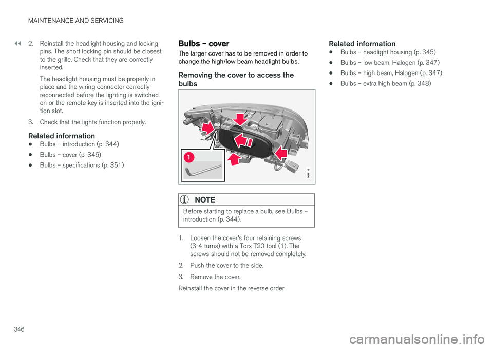
Bulbs – cover The larger cover has to be removed in order to change the high/low beam headlight bulbs.
Removing the cover to access the
bulbs
NOTE
Before starting to replace a bulb, see Bulbs – introduction (p. 344).
1. Loosen the cover's four retaining screws (3-4 turns) with a Torx T20 tool (1). The screws should not be removed completely.
2. Push the cover to the side.
3. Remove the cover.Reinstall the cover in the reverse order.
Related information
• Bulbs – headlight housing (p. 345)
• Bulbs – low beam, Halogen (p. 347)
• Bulbs – high beam, Halogen (p. 347)
• Bulbs – extra high beam (p. 348)
Page 349 of 406
MAINTENANCE AND SERVICING
347
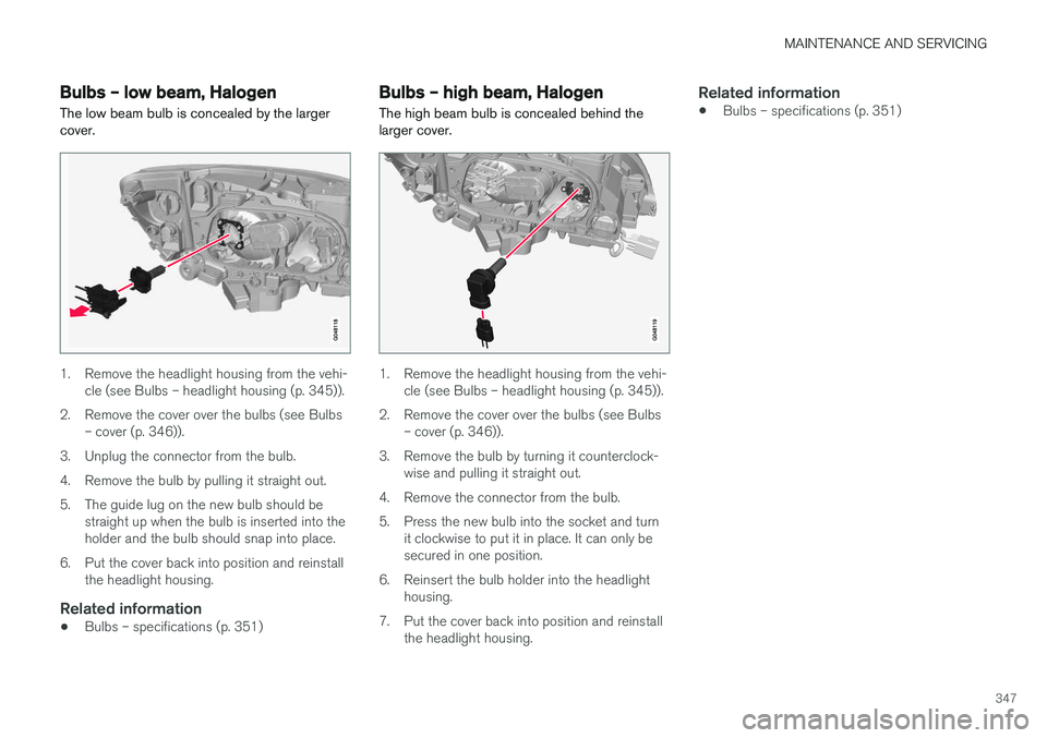
Bulbs – low beam, Halogen The low beam bulb is concealed by the larger cover.
1. Remove the headlight housing from the vehi-cle (see Bulbs – headlight housing (p. 345)).
2. Remove the cover over the bulbs (see Bulbs – cover (p. 346)).
3. Unplug the connector from the bulb.
4. Remove the bulb by pulling it straight out.
5. The guide lug on the new bulb should be straight up when the bulb is inserted into the holder and the bulb should snap into place.
6. Put the cover back into position and reinstall the headlight housing.
Related information
• Bulbs – specifications (p. 351)
Bulbs – high beam, Halogen
The high beam bulb is concealed behind the larger cover.
1. Remove the headlight housing from the vehi- cle (see Bulbs – headlight housing (p. 345)).
2. Remove the cover over the bulbs (see Bulbs – cover (p. 346)).
3. Remove the bulb by turning it counterclock- wise and pulling it straight out.
4. Remove the connector from the bulb.
5. Press the new bulb into the socket and turn it clockwise to put it in place. It can only be secured in one position.
6. Reinsert the bulb holder into the headlight housing.
7. Put the cover back into position and reinstall the headlight housing.
Related information
• Bulbs – specifications (p. 351)
Page 350 of 406
MAINTENANCE AND SERVICING
348
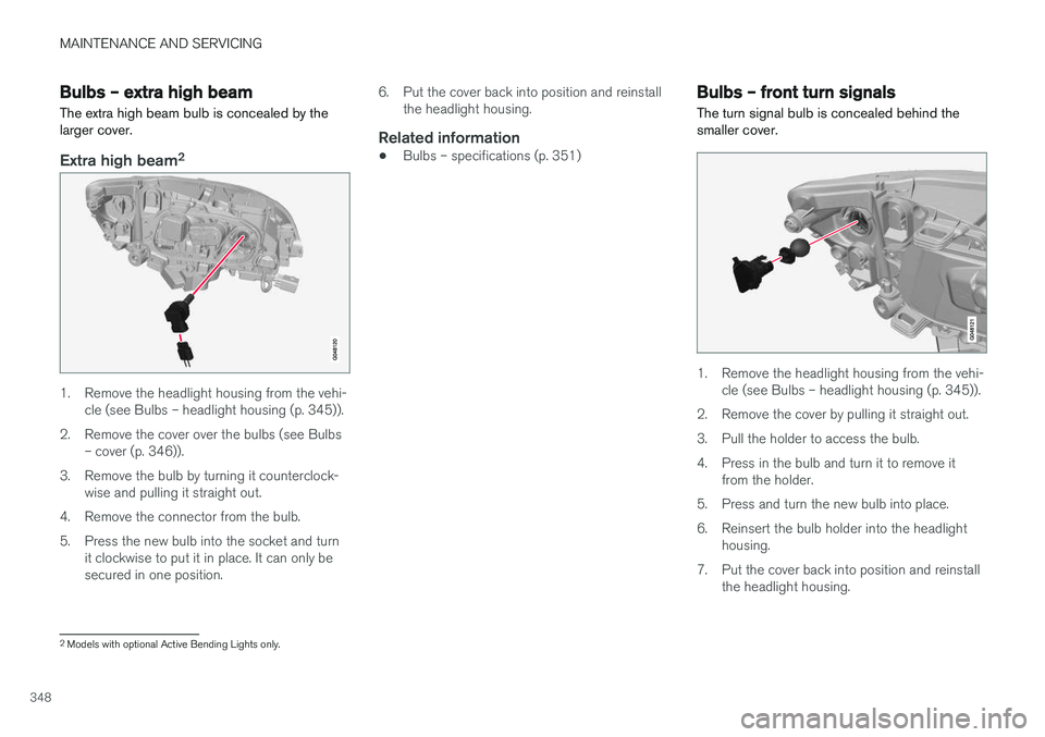
Bulbs – extra high beam The extra high beam bulb is concealed by the larger cover.
Extra high beam2
1. Remove the headlight housing from the vehi-
cle (see Bulbs – headlight housing (p. 345)).
2. Remove the cover over the bulbs (see Bulbs – cover (p. 346)).
3. Remove the bulb by turning it counterclock- wise and pulling it straight out.
4. Remove the connector from the bulb.
5. Press the new bulb into the socket and turn it clockwise to put it in place. It can only be secured in one position. 6. Put the cover back into position and reinstall
the headlight housing.
Related information
• Bulbs – specifications (p. 351)
Bulbs – front turn signals The turn signal bulb is concealed behind the smaller cover.
1. Remove the headlight housing from the vehi-
cle (see Bulbs – headlight housing (p. 345)).
2. Remove the cover by pulling it straight out.
3. Pull the holder to access the bulb.
4. Press in the bulb and turn it to remove it from the holder.
5. Press and turn the new bulb into place.
6. Reinsert the bulb holder into the headlight housing.
7. Put the cover back into position and reinstall the headlight housing.
2Models with optional Active Bending Lights only.