battery VOLVO V60 2017 Owner´s Manual
[x] Cancel search | Manufacturer: VOLVO, Model Year: 2017, Model line: V60, Model: VOLVO V60 2017Pages: 406, PDF Size: 9.65 MB
Page 6 of 406
4
CLIMATE
Climate – general information126
Climate – sensors 126
Air quality 127
Interior Air Quality System (IAQS) *
128
Climate – menu settings 128
Air distribution – general 129
Electronic climate control (ECC) 130
Heated seats 131
Temperature and blower control 132
Automatic climate control 132
Air conditioning 133
Max. defroster and electrically heated windshield * 133
Air distribution – function 134
Air distribution – recirculation 135
Air distribution – table 136
LOADING AND STORAGE
Storage spaces140
Tunnel console 142
Tunnel console – 12-volt sockets 142
Glove compartment 143
Vanity mirror 143
12-volt socket in the cargo area *
143
Loading – general 144
Loading – roof load carriers 144
Load anchoring eyelets 145
Grocery bag holder 146
Cargo net – mounting/removing 146
Cargo area cover 147
Steel cargo grid 148
LOCKS AND ALARM
Remote key and key blade150
Remote key – loss 150
Key memory 151
Locking/unlocking confirmation 152
Immobilizer (start inhibitor) 152
Remote key – functions 153
Remote key – range 154
Detachable key blade – general information 155
Detachable key blade – detaching/reinserting 155
Detachable key blade – unlocking 156
Private locking 156
Remote key – replacing the battery 157
Keyless drive *– locking/unlocking
159
Keyless drive * – unlocking with key blade
160
Keyless drive * – key memory
161
Keyless drive * – messages
161
Keyless drive * – antenna locations
162
Locking/unlocking – from the outside 163
Manual locking 164
Locking/unlocking – from inside 164
Locking/unlocking – glove compartment 166
Locking/unlocking – tailgate 166
Alarm – general information 168
Page 10 of 406
8
MAINTENANCE AND SERVICING
Maintenance – introduction332
Maintenance – owner maintenance 333
Maintenance – hoisting 334
Onboard Diagnostic System 335
Booking service and repairs 335
Maintenance – opening/closing hood 337
Engine compartment – overview 338
Engine compartment – engine oil 339
Engine compartment – coolant 341
Engine compartment – brake fluid 342
Engine compartment – power steer- ing fluid 343
Bulbs – introduction 344
Bulbs – headlight housing 345
Bulbs – cover 346
Bulbs – low beam, Halogen 347
Bulbs – high beam, Halogen 347
Bulbs – extra high beam 348
Bulbs – front turn signals 348
Bulbs – taillight housing 349
Bulbs – license plate lighting 350
Bulbs – cargo area lighting 350
Bulbs – vanity mirror lighting 350
Bulbs – specifications 351
Wiper blades – service position 351
Wiper blades – windshield352
Wiper blades – tailgate 353
Engine compartment – washer fluid 354
Battery – symbols 354
Battery – handling 355
Battery – maintenance 356
Battery – changing 357
Fuses – introduction 359
Fuses – engine compartment 360
Fuses – glove compartment 363
Fuses – cargo area/trunk 366
Fuses – engine compartment cold zone (Start/Stop only) 367
Washing the car 369
Automatic car wash 370
Polishing and waxing 371
Cleaning the interior 371
Touching up paintwork 373
SPECIFICATIONS
Label information376
Dimensions 379
Weights 381
Engine specifications 383
Oil specifications 384
Oil volume 385
Coolant – specification and volume 386
Transmission oil – specification and volumes 386
Brake fluid – specification and volume 386
Power steering – specification 387
Fuel tank volume – specification andvolume 387
Tire inflation – pressure table 388
Air conditioning – specification andvolume 389
Battery specifications 390
Symbols – general information 391
Warning symbols 391
Indicator symbols 392
Information symbols 393
Information symbols – ceiling console 394
Information symbols – center console 394
Page 36 of 406
||
SAFETY
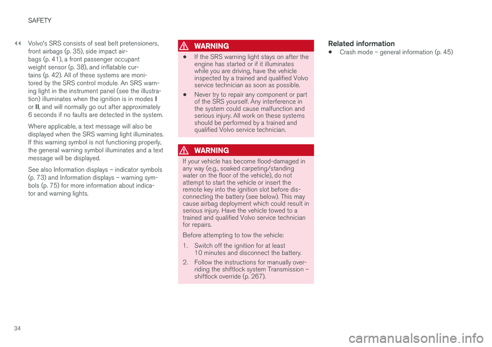
34Volvo's SRS consists of seat belt pretensioners, front airbags (p. 35), side impact air-bags (p. 41), a front passenger occupantweight sensor (p. 38), and inflatable cur-tains (p. 42). All of these systems are moni-tored by the SRS control module. An SRS warn-ing light in the instrument panel (see the illustra- tion) illuminates when the ignition is in modes
I
or II, and will normally go out after approximately
6 seconds if no faults are detected in the system. Where applicable, a text message will also be displayed when the SRS warning light illuminates.If this warning symbol is not functioning properly,the general warning symbol illuminates and a textmessage will be displayed. See also Information displays – indicator symbols (p. 73) and Information displays – warning sym-bols (p. 75) for more information about indica-tor and warning lights.
WARNING
• If the SRS warning light stays on after the engine has started or if it illuminateswhile you are driving, have the vehicleinspected by a trained and qualified Volvoservice technician as soon as possible.
• Never try to repair any component or partof the SRS yourself. Any interference inthe system could cause malfunction andserious injury. All work on these systemsshould be performed by a trained andqualified Volvo service technician.
WARNING
If your vehicle has become flood-damaged in any way (e.g., soaked carpeting/standingwater on the floor of the vehicle), do notattempt to start the vehicle or insert theremote key into the ignition slot before dis-connecting the battery (see below). This maycause airbag deployment which could result inserious injury. Have the vehicle towed to atrained and qualified Volvo service technicianfor repairs. Before attempting to tow the vehicle:
1. Switch off the ignition for at least
10 minutes and disconnect the battery.
2. Follow the instructions for manually over- riding the shiftlock system Transmission – shiftlock override (p. 267).
Related information
•Crash mode – general information (p. 45)
Page 82 of 406
||
INSTRUMENTS AND CONTROLS
* Option/accessory, for more information, see Introduction.
80
CAUTION
Foreign objects in the ignition slot can impair function or cause damage.
Removing the remote keyThe remote key can be removed from the ignition slot by pulling it out.
Related information
• Ignition modes (p. 80)
Ignition modes
The vehicle's ignition has 3 modes: 0, I, and II
that can be used without starting the engine. The following table shows examples of whichfunctions are available in the respective modes.
NOTE
To access ignition modes I or II without star-
ting the engine, the brake pedal must not be
depressed.
ModeFunction
0The odometer, clock and temperature gauge are illuminated. Power seats *
can be adjusted and the infotainment system can be used for a limited time(to minimize battery drain, see theSensus Infotainment Supplement).
IThe Moonroof *, power windows,12-
volt sockets in the passenger com- partment, navigation system *, climate
system blower, windshield wipers can be used.
IIThe headlights/taillights illuminate. Warning/indicator lights illuminate for5 seconds. Other systems are acti- vated. However, the heated seats * and
heated rear window function can only be activated when the engine is run- ning. Mode II should only be used
for very short periods to help avoid draining the battery.
Ignition modes
Ignition mode 0
–The vehicle is unlocked.
Page 105 of 406
INSTRUMENTS AND CONTROLS
103
Power windows
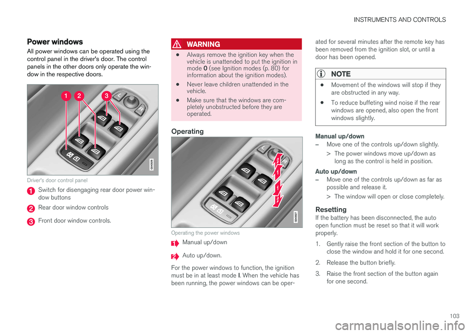
All power windows can be operated using the control panel in the driver's door. The controlpanels in the other doors only operate the win-dow in the respective doors.
Driver's door control panel
Switch for disengaging rear door power win- dow buttons
Rear door window controls
Front door window controls.
WARNING
• Always remove the ignition key when the vehicle is unattended to put the ignition in mode
0 (see Ignition modes (p. 80) for
information about the ignition modes).
• Never leave children unattended in the vehicle.
• Make sure that the windows are com-pletely unobstructed before they areoperated.
Operating
Operating the power windows
Manual up/down
Auto up/down.
For the power windows to function, the ignition must be in at least mode I. When the vehicle has
been running, the power windows can be oper- ated for several minutes after the remote key has been removed from the ignition slot, or until adoor has been opened.
NOTE
•
Movement of the windows will stop if they are obstructed in any way.
• To reduce buffeting wind noise if the rearwindows are opened, also open the frontwindows slightly.
Manual up/down
–Move one of the controls up/down slightly.
> The power windows move up/down as
long as the control is held in position.
Auto up/down
–Move one of the controls up/down as far as possible and release it.
> The window will open or close completely.
ResettingIf the battery has been disconnected, the auto open function must be reset so that it will workproperly.
1. Gently raise the front section of the button to close the window and hold it for one second.
2. Release the button briefly.
3. Raise the front section of the button again for one second.
Page 108 of 406
INSTRUMENTS AND CONTROLS
* Option/accessory, for more information, see Introduction.
106
Heated windshield *, rear window
and door mirror defrosters
The heating function is used to defrost/de-ice the windshield and/or the rear window and doormirrors.
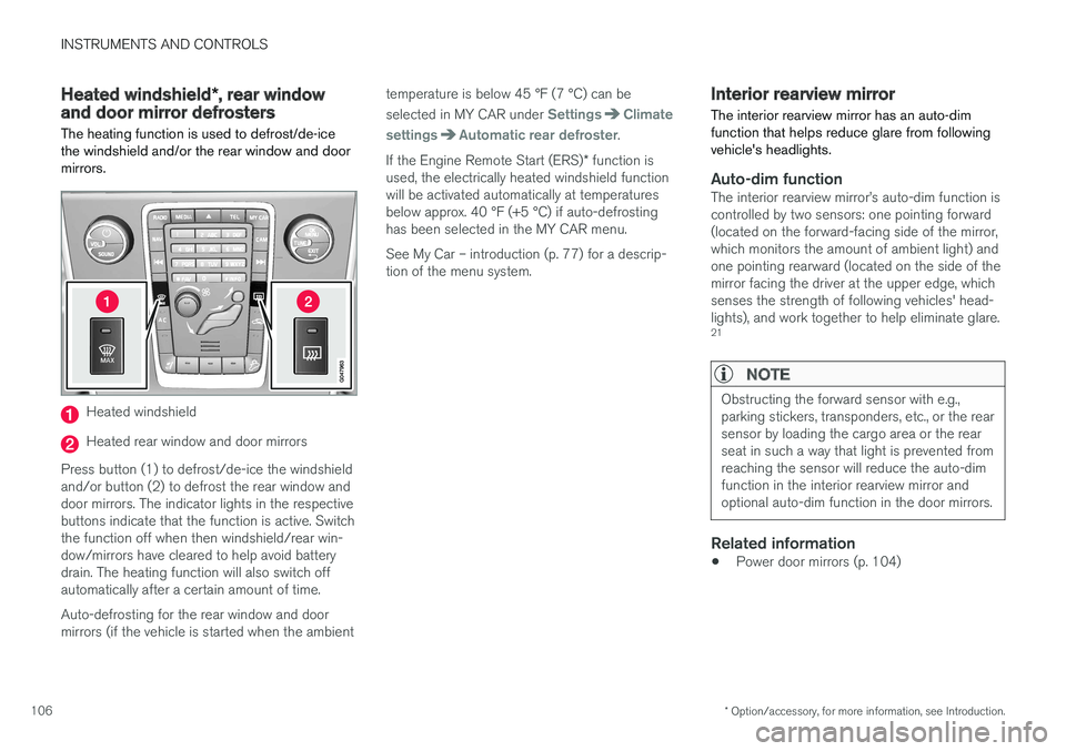
Heated windshield
Heated rear window and door mirrors
Press button (1) to defrost/de-ice the windshield and/or button (2) to defrost the rear window anddoor mirrors. The indicator lights in the respectivebuttons indicate that the function is active. Switchthe function off when then windshield/rear win-dow/mirrors have cleared to help avoid batterydrain. The heating function will also switch offautomatically after a certain amount of time. Auto-defrosting for the rear window and door mirrors (if the vehicle is started when the ambient temperature is below 45 °F (7 °C) can be selected in MY CAR under
SettingsClimate
settings
Automatic rear defroster.
If the Engine Remote Start (ERS) * function is
used, the electrically heated windshield function will be activated automatically at temperaturesbelow approx. 40 °F (+5 °C) if auto-defrostinghas been selected in the MY CAR menu. See My Car – introduction (p. 77) for a descrip- tion of the menu system.
Interior rearview mirror The interior rearview mirror has an auto-dim function that helps reduce glare from followingvehicle's headlights.
Auto-dim functionThe interior rearview mirror
Page 113 of 406
INSTRUMENTS AND CONTROLS
}}
* Option/accessory, for more information, see Introduction.111
well as for future HomeLink programming. It is also suggested that upon the sale of the vehicle,the programmed HomeLink buttons be erasedfor security purposes. Refer to “Resetting Home- Link Buttons” in HomeLink
®
Wireless Control
System * – programming (p. 111).
Using HomeLinkTo operate, simply press and hold the pro- grammed HomeLink button until the traineddevice begins to operate (this may take severalseconds). Activation will now occur for the traineddevice (i.e., garage door opener, gate operator,security system, entry door lock, home/officelighting, etc.). For convenience, the hand-heldtransmitter of the device may also be used at anytime. In the event that there are still programmingdifficulties or questions, contact HomeLink at:www.homelink.com/www.youtube.com/HomeLinkGentex or by phoning the hotline at 1–800–355–3515.
NOTE
If the ignition is switched off, HomeLink will function for 30 minutes after the driver's doorhas been opened.
HomeLink ®
Wireless Control
System * – programming
The HomeLink Wireless Control System pro- vides a convenient way to replace up to threehand-held radio-frequency (RF) transmittersused to activate devices such as gate operators,garage door openers, entry door locks, securitysystems, even home lighting. Additional informa-tion can be found on the Internetatwww.homelink.com/www.youtube.com/HomeLinkGentex or by phoning the hotline at 1–800–355–3515.
NOTE
Some vehicles may require the ignition to be switched on or be in the “accessories” posi-tion for programming and/or operation ofHomeLink. It is also recommended that a newbattery be placed in the hand-held transmitterof the device being programmed to Home-Link for quicker training and accurate trans-mission of the radio-frequency signal. TheHomeLink buttons must be reset first. Whenthis has been completed, Homelink is inlearning mode so that you can perform pro-gramming.
1. Position the end of your hand-held transmit- ter 1–3 inches (5–14 cm) away from the HomeLink button you wish to program whilekeeping the indicator light in view. 2. Simultaneously press and hold both the
chosen HomeLink and hand-held transmitterbuttons until the HomeLink indicator lightchanges from a slow to a rapidly blinkinglight. Now you may release both the Home-Link and hand-held transmitter buttons.
NOTE
Some devices may require you to replace this Programming Step 2 with procedures notedin the “Gate Operator / Canadian Program-ming” section. If the HomeLink indicator lightdoes not change to a rapidly blinking lightafter performing these steps, contact Home-Link at www.homelink.com/www.youtube.com/HomeLinkGentex or byphoning the hotline at 1–800–355–3515.
Page 118 of 406
||
INSTRUMENTS AND CONTROLS
116
MessageDescription
Time for reg- ular mainte-nanceTime for regular service at an authorized Volvo workshop.The timing is determined bythe number of miles driven,number of months since thelast service, engine runningtime.
Maintenance overdueIf the service intervals are not followed, the warranty doesnot cover any damaged parts.Contact an authorized Volvoworkshop for service.
Temporarily OFFAA function has been tempo- rarily switched off and isreset automatically while driv-ing or after starting again.
Low battery Power savemodeThe audio system is switched off to save current. Chargethe battery.
AThere will also be a system-specific part of this message
Related information
• Information displays – introduction (p. 69)
• Information display – menu overview (p. 115)
• Information display – menu controls (p. 114)
Trip computer – introduction
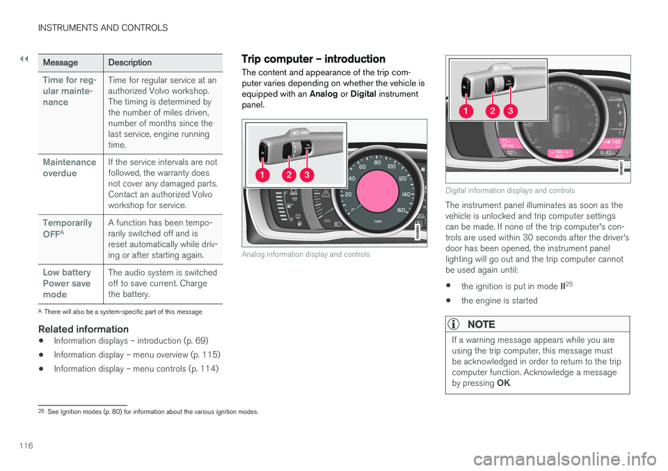
The content and appearance of the trip com- puter varies depending on whether the vehicle isequipped with an Analog or Digital instrument
panel.
Analog information display and controls
Digital information displays and controls
The instrument panel illuminates as soon as the vehicle is unlocked and trip computer settingscan be made. If none of the trip computer's con-trols are used within 30 seconds after the driver'sdoor has been opened, the instrument panellighting will go out and the trip computer cannotbe used again until: • the ignition is put in mode
II25
• the engine is started
NOTE
If a warning message appears while you are using the trip computer, this message mustbe acknowledged in order to return to the tripcomputer function. Acknowledge a message by pressing
OK.
25
See Ignition modes (p. 80) for information about the various ignition modes.
Page 158 of 406
LOCKS AND ALARM
156
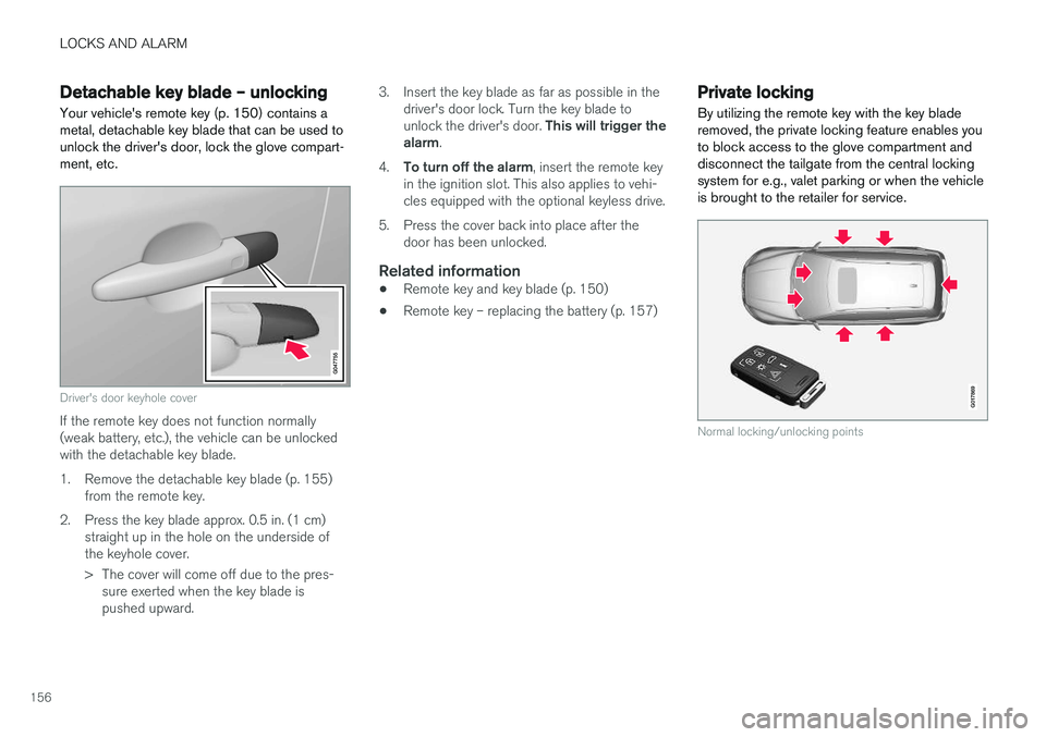
Detachable key blade – unlockingYour vehicle's remote key (p. 150) contains a metal, detachable key blade that can be used tounlock the driver's door, lock the glove compart-ment, etc.
Driver's door keyhole cover
If the remote key does not function normally (weak battery, etc.), the vehicle can be unlockedwith the detachable key blade.
1. Remove the detachable key blade (p. 155) from the remote key.
2. Press the key blade approx. 0.5 in. (1 cm) straight up in the hole on the underside of the keyhole cover.
> The cover will come off due to the pres-sure exerted when the key blade is pushed upward. 3. Insert the key blade as far as possible in the
driver's door lock. Turn the key blade to unlock the driver's door. This will trigger the
alarm .
4. To turn off the alarm , insert the remote key
in the ignition slot. This also applies to vehi- cles equipped with the optional keyless drive.
5. Press the cover back into place after the door has been unlocked.
Related information
• Remote key and key blade (p. 150)
• Remote key – replacing the battery (p. 157)
Private locking
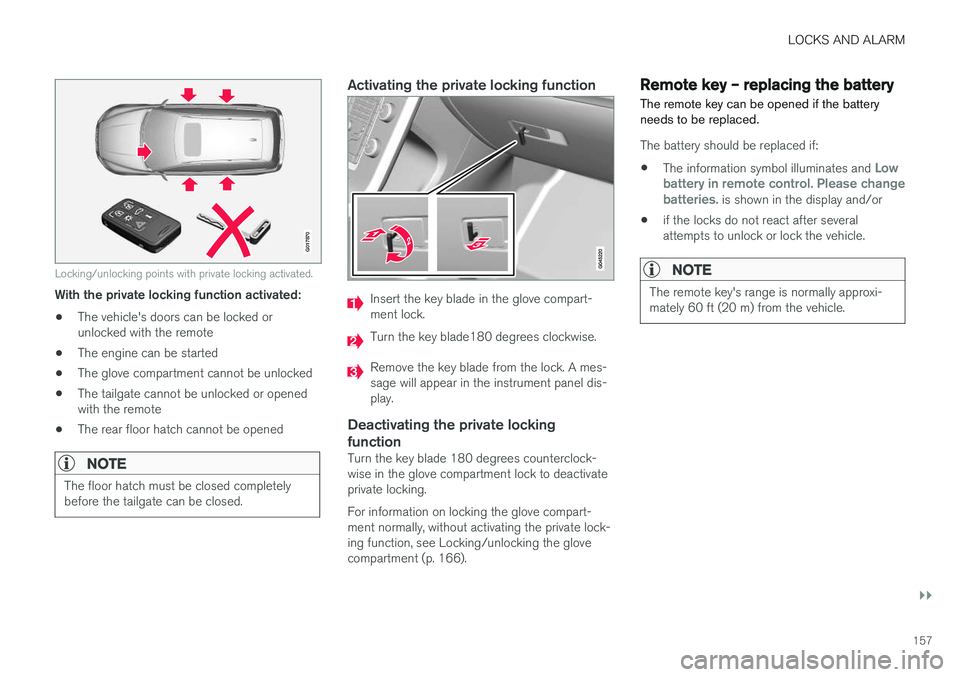
By utilizing the remote key with the key blade removed, the private locking feature enables youto block access to the glove compartment anddisconnect the tailgate from the central lockingsystem for e.g., valet parking or when the vehicleis brought to the retailer for service.
G017869
Normal locking/unlocking points
Page 159 of 406
LOCKS AND ALARM
}}
157
G017870
Locking/unlocking points with private locking activated.
With the private locking function activated:• The vehicle's doors can be locked or unlocked with the remote
• The engine can be started
• The glove compartment cannot be unlocked
• The tailgate cannot be unlocked or openedwith the remote
• The rear floor hatch cannot be opened
NOTE
The floor hatch must be closed completely before the tailgate can be closed.
Activating the private locking function
Insert the key blade in the glove compart- ment lock.
Turn the key blade180 degrees clockwise.
Remove the key blade from the lock. A mes- sage will appear in the instrument panel dis-play.
Deactivating the private locking function
Turn the key blade 180 degrees counterclock- wise in the glove compartment lock to deactivateprivate locking. For information on locking the glove compart- ment normally, without activating the private lock-ing function, see Locking/unlocking the glovecompartment (p. 166).
Remote key – replacing the battery The remote key can be opened if the battery needs to be replaced.
The battery should be replaced if:
• The information symbol illuminates and
Low
battery in remote control. Please change batteries.
is shown in the display and/or
• if the locks do not react after several attempts to unlock or lock the vehicle.
NOTE
The remote key's range is normally approxi- mately 60 ft (20 m) from the vehicle.