ABS VOLVO V60 2018 Owner´s Manual
[x] Cancel search | Manufacturer: VOLVO, Model Year: 2018, Model line: V60, Model: VOLVO V60 2018Pages: 406, PDF Size: 9.59 MB
Page 9 of 406
7
Brakes – symbols 278
Anti-lock braking system (ABS) 279
Brake lights 279
Emergency Brake Assistance (EBA) 279
Parking brake – general information 280
Parking brake – applying 281
Parking brake – releasing 281
Parking brake – symbols and messages 283
Driving through water 284
Engine and cooling system 284
Conserving electrical current 285
Before a long distance trip 285
Driving in cold weather 286
Refueling – fuel requirements 286
Refueling – octane rating 287
Refueling – opening/closing fuel filler door 289
Refueling – opening/closing fuel cap 290
Emission controls 290
Economical driving 291
Towing a trailer 292
Trailer Stability Assist (TSA) 294
Towing the vehicle 295
Towing eyelet 295
Towing by tow truck 296
WHEELS AND TIRES
Tires – general information300
Tires – storage and age 301
Tires – tread wear indicator 302
Tires – tire economy 302
Changing a wheel – direction of rotation 303
Changing a wheel – removing wheel 303
Changing a wheel – spare wheel 306
Changing a wheel – accessing the spare wheel 307
Changing a wheel – installing a wheel 307
Tire inflation – general information 308
Tire inflation – checking pressure 309
Tire specifications 310
Loading specifications 312
Loading specifications – load limit 312
Tire specifications – terminology 313
Tire specifications – Uniform TireQuality Grading 314
Snow chains 315
Snow tires/studded tires 316
Tire pressure monitoring - overview 316
Tire Monitor - introduction 317
Calibrating Tire Monitor 318
Tire Monitor status information 319
Tire Monitor – messages 319
Tire Pressure Monitoring System (TPMS) – general information320
Tire Pressure Monitoring System(TPMS) – changing wheels 321
Tire Pressure Monitoring System(TPMS) – recalibrating 322
Tire Pressure Monitoring System(TPMS) – activating/deactivating 322
Tire Pressure Monitoring System(TPMS) – messages 323
Tire sealing system * – general infor-
mation 324
Tire sealing system * – overview
325
Tire sealing system * – sealing a hole
327
Tire sealing system – checking infla-tion pressure 329
Tire sealing system * – inflating tires
329
Tire sealing system * – sealing com-
pound container 330
Page 20 of 406
||
INTRODUCTION
18
Bullet lists
Bullets are used to differentiate a number of components/functions/points of information thatcan be listed in random order. For example:• Coolant
• Engine oil
Continues on next page
}
}This symbol can be found at the lower right
corner to indicate that the current topic continues on the following page.
Continuation from previous page
|| This symbol can be found at the upper left
corner to indicate that the current topic is a con- tinuation from the previous page.
Options and accessoriesOptional or accessory equipment described inthis manual is indicated by an asterisk. Optional or accessory equipment may not be available in all countries or markets. Please notethat some vehicles may be equipped differently,depending on special legal requirements. Contact your Volvo retailer for additional informa- tion.
WARNING
If your vehicle is involved in an accident, unseen damage may affect its drivability andsafety.
WARNING
CALIFORNIA proposition 65 Engine exhaust, some of its constituents, and certain vehicle components contain or emitchemicals known to the state of California tocause cancer, and birth defects or otherreproductive harm. In addition, certain fluidscontained in vehicles and certain products ofcomponent wear contain or emit chemicalsknown to the State of California to cause can-cer, and birth defects or other reproductiveharm.
WARNING
Certain components of this vehicle such as air bag modules, seat belt pretensioners, adap-tive steering columns, and button cell batter-ies may contain Perchlorate material. Specialhandling may apply for service or vehicle endof life disposal. See www.dtsc.ca.gov/hazardouswaste/ perchlorate.
ShiftlockWhen your vehicle is parked, the gear selector is locked in the P (Park) position. To release the selector from this position, the ignition must be inmode
II (p. 82) or the engine must be running.
Depress the brake pedal, press the button on the front side of the gear selector and move the selector from P (Park).
Anti-lock Brake System (ABS)The ABS system performs a brief self-diagnostic test when the engine has been started and driverreleases the brake pedal. Another automatic testmay be performed when the vehicle first reachesa speed of approximately 6 mph (10 km/h). Thebrake pedal will pulsate several times and asound may be audible from the ABS controlmodule. This is normal.
Fuel filler doorPress the button on the light switch panel (seethe illustration in Refueling – opening/closingfuel filler door (p. 289)) when the vehicle is at astandstill to unlock the fuel filler door. It willrelock when closed and there will be an audibleclick.
Points to keep in mind
• Do not export your Volvo to another countrybefore investigating that country's applicablesafety and exhaust emission requirements. Insome cases it may be difficult or impossibleto comply with these requirements. Modifica-tions to the emission control system(s) mayrender your Volvo not certifiable for legal
Page 30 of 406
SAFETY
28
Occupant safety Safety is Volvo's cornerstone.
Volvo's concern for safetyOur concern for safety dates back to 1927 when the first Volvo rolled off the production line.Three-point seat belts (a Volvo invention), safetycages, and energy-absorbing impact zones weredesigned into Volvo vehicles long before it wasfashionable or required by government regulation. We will not compromise our commitment to safety. We continue to seek out new safety fea-tures and to refine those already in our vehicles.You can help. We would appreciate hearing yoursuggestions about improving automobile safety.We also want to know if you ever have a safetyconcern with your vehicle. Call us in the U.S. at:1-800-458-1552 or in Canada at:1-800-663-8255.
Occupant safety reminders
How safely you drive doesn't depend on how old you are but rather on:
• How well you see.
• Your ability to concentrate.
• How quickly you make decisions understress to avoid an accident.
The following suggestions are intended to helpyou cope with the ever changing traffic environ-ment. •
Never drink and drive.
• If you are taking any medication, consult yourphysician about its potential effects on yourdriving abilities.
• Take a driver-retraining course.
• Have your eyes checked regularly.
• Keep your windshield and headlights clean.
• Replace wiper blades when they start toleave streaks.
• Take into account the traffic, road, andweather conditions, particularly with regard tostopping distance.
• Never send text messages while driving.
• Refrain from using or minimize the use of acell phone while driving.
Related information
• Recall information (p. 28)
• Reporting safety defects (p. 29)
Recall information Information regarding recalls or other service campaigns is available on our website atwww.volvocars.com/us/.
On our website, select the "Own" tab on the upper left side of the screen and click the head-ing "Recall Information" on the right side of thescreen. Enter your Vehicle Identification Number(VIN) for your vehicle (found at the base of thewindshield). If your vehicle has any open Recalls,they will be displayed on this page.
Volvo customers in Canada
For any questions regarding open recalls for your vehicle, please contact your authorized Volvoretailer. If your retailer is unable to answer yourquestions, please contact Volvo Customer Rela-tions at 800-663-8255, Monday through Friday,8:30 A.M. to 5:00 P.M. EST or volvocars.com/ca.You may also write us at: Volvo Car Canada Ltd.Customer Care Centre9130 Leslie Street, Suite 101Richmond Hill, Ontario L4B 0B9
Related information
•Occupant safety (p. 28)
• Reporting safety defects (p. 29)
Page 46 of 406
||
SAFETY
44
Related information
•Supplemental Restraint System (SRS) (p. 33)
• Front airbags (p. 35)
• Child safety (p. 48)
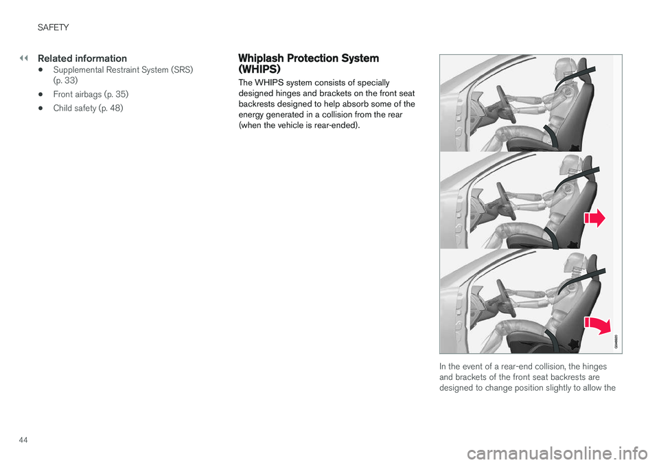
Whiplash Protection System (WHIPS) The WHIPS system consists of specially designed hinges and brackets on the front seatbackrests designed to help absorb some of theenergy generated in a collision from the rear(when the vehicle is rear-ended).
In the event of a rear-end collision, the hinges and brackets of the front seat backrests aredesigned to change position slightly to allow the
Page 47 of 406
SAFETY
}}
45
backrest/head restraint to help support the occu- pant's head before moving slightly rearward. Thismovement helps absorb some of the forces thatcould result in whiplash.
WARNING
•
The WHIPS system is designed to sup- plement the other safety systems in yourvehicle. For this system to function prop-erly, the three-point seat belt must beworn. Please be aware that no systemcan prevent all possible injuries that mayoccur in an accident.
• The WHIPS system is designed to func-tion in certain collisions from the rear,depending on the crash severity, angleand speed.
WARNING
•
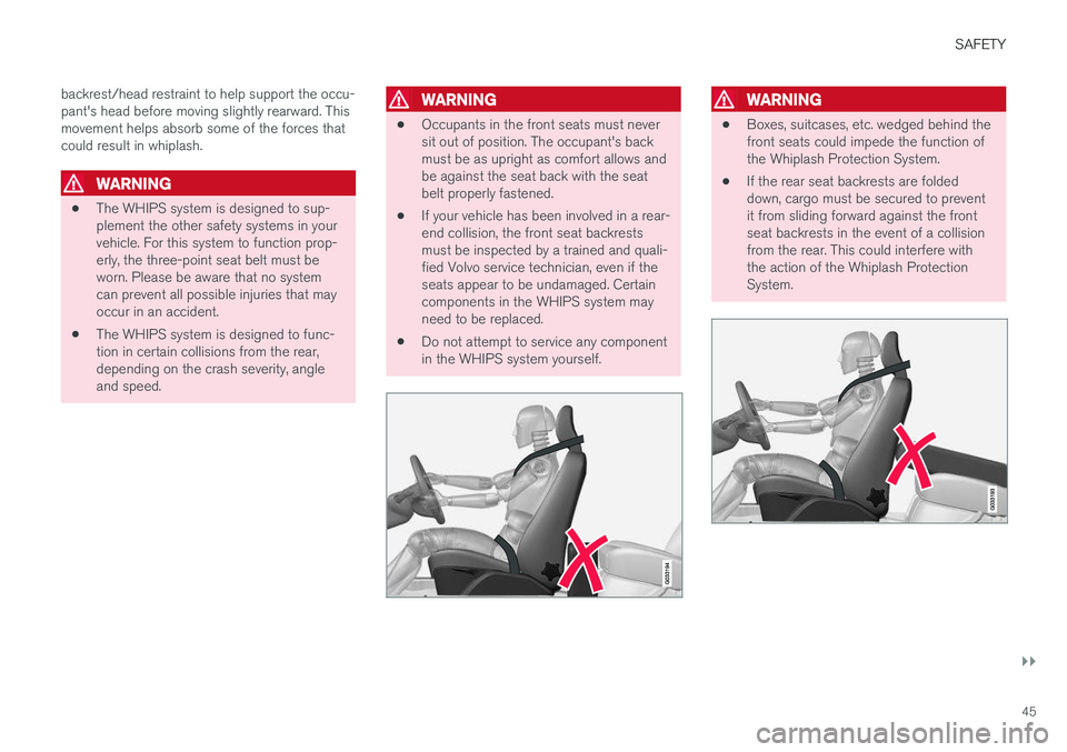
Occupants in the front seats must never sit out of position. The occupant's backmust be as upright as comfort allows andbe against the seat back with the seatbelt properly fastened.
• If your vehicle has been involved in a rear-end collision, the front seat backrestsmust be inspected by a trained and quali-fied Volvo service technician, even if theseats appear to be undamaged. Certaincomponents in the WHIPS system mayneed to be replaced.
• Do not attempt to service any componentin the WHIPS system yourself.
WARNING
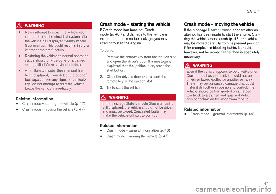
•Boxes, suitcases, etc. wedged behind the front seats could impede the function ofthe Whiplash Protection System.
• If the rear seat backrests are foldeddown, cargo must be secured to preventit from sliding forward against the frontseat backrests in the event of a collisionfrom the rear. This could interfere withthe action of the Whiplash ProtectionSystem.
Page 49 of 406
SAFETY
47
WARNING
•Never attempt to repair the vehicle your- self or to reset the electrical system after the vehicle has displayed
Safety mode
See manual. This could result in injury or
improper system function.
• Restoring the vehicle to normal operating status should only be done by a trainedand qualified Volvo service technician.
• After
Safety mode See manual has
been displayed, if you detect the odor of fuel vapor, or see any signs of fuel leak-age, do not attempt to start the vehicle.Leave the vehicle immediately.
Related information
• Crash mode – starting the vehicle (p. 47)
• Crash mode – moving the vehicle (p. 47)
Crash mode – starting the vehicle
If Crash mode has been set Crash mode (p. 46)) and damage to the vehicle isminor and there is no fuel leakage, you mayattempt to start the engine.
To do so:
1. Remove the remote key from the ignition slot and open the driver's door. If a message is displayed that the ignition is on, press thestart button.
2. Close the driver's door and reinsert the remote key in the ignition slot.
3. Try to start the vehicle.
WARNING
If the message Safety mode See manual is
still displayed, the vehicle should not be driven and must be towed. Concealed faults maymake the vehicle difficult to control.
Related information
• Crash mode – general information (p. 46)
• Crash mode – moving the vehicle (p. 47)
Crash mode – moving the vehicle
If the message
Normal mode appears after an
attempt has been made to start the engine, Star- ting the vehicle after a crash (p. 47), the vehiclemay be moved carefully from its present position,if for example, it is blocking traffic. It should,however, not be moved farther than is absolutelynecessary.
WARNING
Even if the vehicle appears to be drivable after Crash mode has been set, it should not bedriven or towed (pulled by another vehicle).There may be concealed damage that couldmake it difficult or impossible to control. Thevehicle should be transported on a flatbedtow truck to a trained and qualified Volvoservice technician for inspection/repairs.
Related information
• Crash mode – general information (p. 46)
Page 77 of 406
INSTRUMENTS AND CONTROLS
}}
* Option/accessory.75
Utilized power
The larger, lower indicator shows the amount of engine power that has been utilized 2
. The higher
the reading on the scale, the greater the amount of power that is being utilized. The larger the gap between the two indicators, the greater the amount of power remaining.Information displays – indicator symbols
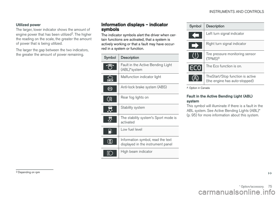
The indicator symbols alert the driver when cer- tain functions are activated, that a system isactively working or that a fault may have occur-red in a system or function.
Symbol Description
Fault in the Active Bending Light (ABL)*system
Malfunction indicator light
Anti-lock brake system (ABS)
Rear fog lights on
Stability system
The stability system's Sport mode is activated
Low fuel level
Information symbol, read the text displayed in the instrument panel
High beam indicator
Symbol Description
Left turn signal indicator
Right turn signal indicator
Tire pressure monitoring sensor (TPMS)A
The Eco function is on.
TheStart/Stop function is active (the engine has auto-stopped)
A
Option in Canada
Fault in the Active Bending Light (ABL)
system
This symbol will illuminate if there is a fault in the ABL system. See Active Bending Lights (ABL) *
(p. 95) for more information about this system.
2 Depending on rpm
Page 78 of 406
||
INSTRUMENTS AND CONTROLS
* Option/accessory.
76
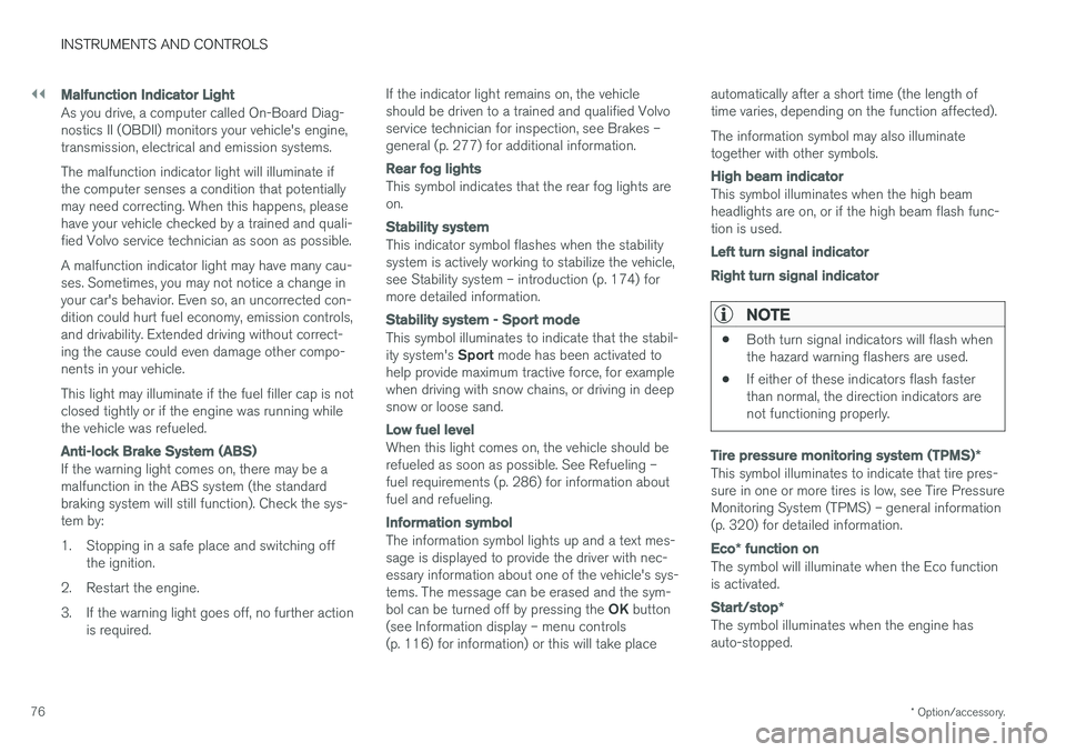
Malfunction Indicator Light
As you drive, a computer called On-Board Diag- nostics II (OBDII) monitors your vehicle's engine,transmission, electrical and emission systems. The malfunction indicator light will illuminate if the computer senses a condition that potentiallymay need correcting. When this happens, pleasehave your vehicle checked by a trained and quali-fied Volvo service technician as soon as possible. A malfunction indicator light may have many cau- ses. Sometimes, you may not notice a change inyour car's behavior. Even so, an uncorrected con-dition could hurt fuel economy, emission controls,and drivability. Extended driving without correct-ing the cause could even damage other compo-nents in your vehicle. This light may illuminate if the fuel filler cap is not closed tightly or if the engine was running whilethe vehicle was refueled.
Anti-lock Brake System (ABS)
If the warning light comes on, there may be a malfunction in the ABS system (the standardbraking system will still function). Check the sys-tem by:
1. Stopping in a safe place and switching off
the ignition.
2. Restart the engine.
3. If the warning light goes off, no further action is required. If the indicator light remains on, the vehicle should be driven to a trained and qualified Volvoservice technician for inspection, see Brakes –general (p. 277) for additional information.
Rear fog lights
This symbol indicates that the rear fog lights are on.
Stability system
This indicator symbol flashes when the stability system is actively working to stabilize the vehicle,see Stability system – introduction (p. 174) formore detailed information.
Stability system - Sport mode
This symbol illuminates to indicate that the stabil- ity system's
Sport mode has been activated to
help provide maximum tractive force, for example when driving with snow chains, or driving in deepsnow or loose sand.
Low fuel level
When this light comes on, the vehicle should be refueled as soon as possible. See Refueling –fuel requirements (p. 286) for information aboutfuel and refueling.
Information symbol
The information symbol lights up and a text mes- sage is displayed to provide the driver with nec-essary information about one of the vehicle's sys-tems. The message can be erased and the sym- bol can be turned off by pressing the OK button
(see Information display – menu controls (p. 116) for information) or this will take place automatically after a short time (the length oftime varies, depending on the function affected). The information symbol may also illuminate together with other symbols.
High beam indicator
This symbol illuminates when the high beam headlights are on, or if the high beam flash func-tion is used.
Left turn signal indicator Right turn signal indicator
NOTE
•
Both turn signal indicators will flash when the hazard warning flashers are used.
• If either of these indicators flash fasterthan normal, the direction indicators arenot functioning properly.
Tire pressure monitoring system (TPMS)
*
This symbol illuminates to indicate that tire pres- sure in one or more tires is low, see Tire PressureMonitoring System (TPMS) – general information(p. 320) for detailed information.
Eco* function on
The symbol will illuminate when the Eco function is activated.
Start/stop *
The symbol illuminates when the engine has auto-stopped.
Page 217 of 406
DRIVER SUPPORT
}}
* Option/accessory.215
body and the person must be at least 32 in. (80 cm) tall.
• The system cannot detect a pedestrian carry-ing a large object.
• The camera's capacity to see a pedestrian atdawn or dusk is limited, much as it is for thehuman eye.
• The camera's function is deactivated and willnot detect a pedestrian in darkness or in tun-nels, even if there is street lighting in thearea.
WARNING
•Pedestrian and Cyclist Detection with Full Auto Brake is designed to be a supple-mentary driving aid. It is not, however,intended to replace the driver's attentionand judgement. The driver is alwaysresponsible for operating the vehicle in asafe manner.
• The system cannot detect all pedestriansin all situations, such as in darkness/atnight and cannot detect partially hiddenpedestrians, people who are less thanapprox. 32 in. (80 cm) tall, or peoplewearing clothing that obscures the con-tours of their bodies.
Related information
•Collision warning – introduction (p. 209)
• Collision warning
* – function (p. 211)
• Collision warning
* – operation (p. 212)
• Collision warning
* – Cyclist detection
(p. 213)
• Collision warning
* – limitations (p. 215)
• Collision warning – troubleshooting (p. 218)
• Collision warning – symbols and messages(p. 220)
Collision warning
* – limitations
Strong sunlight, reflections, extreme light con- trasts, the use of sunglasses, or if the driver is notlooking straight ahead may make the visual warn-ing signal in the windshield difficult to see. Forthis reason, always activate the audible warningsignal. Slippery driving conditions increase braking dis- tance, which can reduce the system's capacity toavoid a collision. In these conditions, the ABS andstability systems provide the best possible brak-ing effect while helping to maintain stability.
NOTE
The visual warning signal may be temporarily disengaged in the event of high passengercompartment temperature due to strong sun-light, etc. If this occurs, the audible warningsignal will be used, even if it has been deacti-vated in the menu system.
Page 244 of 406

DRIVER SUPPORT
* Option/accessory.
242
Park Assist Pilot (PAP) * –
introduction
The Park Assist Pilot provides assistance when parallel parking by measuring the parking spaceand turning the steering wheel.
Introduction
The off/on button shown is located on the center con- sole
Park Assist Pilot (PAP) is a semi-automatic sys- tem that provides assistance when parallel park-ing by:
• Finding a parking space and determining if itis big enough for the vehicle
• Helping to steer the vehicle into the parkingspace
Information about the actions required of thedriver is provided in the instrument panel in theform of symbols, images and text.
NOTE
If a trailer hitch is configured in the vehicle's electrical system, PAP will take the trailerhitch into consideration when determining thenecessary size of a parking space.
WARNING
• PAP does not function in all situations and is only intended to assist the driverwhen parallel parking.
• As the driver, you have full responsibilityfor parking the vehicle in a safe manner.
Related information
•
Park Assist Pilot (PAP)
* – function (p. 242)
• Park Assist Pilot (PAP)
* – operation (p. 243)
• Park Assist Pilot (PAP)
* – limitations
(p. 245)
• Park Assist Pilot (PAP)
* – symbols and mes-
sages (p. 246)
• Park assist – introduction (p. 238)
• Rear Park Assist Camera (PAC) – introduc-tion (p. 247)
Park Assist Pilot (PAP)
* – function
PAP's function is to measure the parking space and to turn the steering wheel during the parallelparking procedure. The driver is responsible forfollowing the instructions shown in the instru- ment panel and for: shifting between R (Reverse)
and D (Drive) when required, regulating the vehi-
cle's speed, applying the brakes and stopping the vehicle. PAP can be activated in the following conditions:
• When the stability or ABS systems are not working actively
• The vehicle is not towing a trailer
• The vehicle's speed is below 30 mph(50 km/h)
How PAP works
PAP helps park the vehicle by: