headlamp VOLVO V90 2017 Owner's Manual
[x] Cancel search | Manufacturer: VOLVO, Model Year: 2017, Model line: V90, Model: VOLVO V90 2017Pages: 594, PDF Size: 15.07 MB
Page 340 of 594
||
DRIVER SUPPORT
338
Low speed
City Safety is not activated at very low speeds - below 4 km/h (3 mph) - and the system there-fore does not intervene in situations where yourcar is approaching a vehicle ahead very slowly,e.g. when parking.
Active driver
Driver commands are always prioritised, which is why City Safety does not intervene or postponewarning/intervention in situations where thedriver is steering and accelerating in a decisivemanner, even if a collision is unavoidable. Active and aware driving behaviour can therefore delay a collision warning and intervention in orderto minimise unnecessary warnings.
Miscellaneous
WARNING
Warnings and brake interventions could be implemented late or not at all if a traffic situa-tion or external influences mean that the cam-era and radar unit cannot detect pedestrians,cyclists, large animals or vehicles correctly. For vehicles to be detected at night, their headlamps and rear lamp cluster must beswitched on and shining clearly. The camera and radar unit has a limited range for pedestrians and cyclists. The system canprovide effective warnings and brake interven-tions as long as the relative speed is below50 km/h (30 mph). For stationary or slow-moving vehicles, warnings and brake interven-tions are effective at vehicle speeds up to70 km/h (43 mph). Speed reduction for largeanimals is less than 15 km/h (9 mph) andcan be achieved at vehicle speeds above70 km/h (43 mph). The warning and brakeintervention for large animals is less effectiveat lower speeds. Warnings for stationary or slow-moving vehi- cles and large animals could be disengageddue to darkness or poor visibility. Warnings and brake interventions for pedes- trians and cyclists are deactivated at vehiclespeeds exceeding 70 km/h (43 mph). Do not place, stick or mount anything on the outside or inside of the windscreen in front ofor around the camera and radar unit — thiscan interfere with camera-dependent func-tions.
Objects, snow, ice or dirt in the area of the camera sensor may reduce its function, fullydeactivate it or give incorrect functionresponse.
NOTE
The function uses the car's camera unit, which has some general limitations, see the"Limitations for camera unit" section.
NOTE
The function uses the car's radar unit, which has some general limitations, see the "Limita-tions for radar unit" section.
Related information
•City Safety (p. 330)
• Limitations of the camera unit (p. 327)
• Limitations of the radar unit (p. 319)
Page 387 of 594
STARTING AND DRIVING
}}
385
Ignition positions The car's electrical system can be set in different levels/positions and in this way make the differ-ent functions available.
In order to facilitate the use of a limited number of functions with the engine switched off, thecar's electrical system can be set in 3 different levels - 0, I and II. These levels are described
with the denomination "ignition position" throughout the owner's manual. The following table shows the functions available in each ignition position/level:
Level Functions
0 •Odometer, clock and temperature gauge are illuminated.
• Power seats can be adjusted.
• The power windows can be used.
• The centre display is started andcan be used.
• It is possible to start the audio.
The functions are time-controlled inthis ignition position and are switchedoff automatically after a period of time.
I •Panorama roof, power windows,12V socket in the passenger com-partment, navigation, phone, venti-lation fan and windscreen wiperscan be used.
• Power seats can be adjusted.
• 12 V sockets in the cargo areacan be used.
• The audio is started automaticallyif it was running when the car wasleft.
Power is taken from the battery inthis ignition position.Level Functions
II •The headlamps come on.
• Warning/indicator lamps illuminate for 5 seconds.
• Several other systems are acti-vated. However, heating in seatcushions and the rear window canonly be activated after the car hasbeen started.
This ignition position consumes alot of current from the battery andshould therefore be avoided!
Selecting ignition position
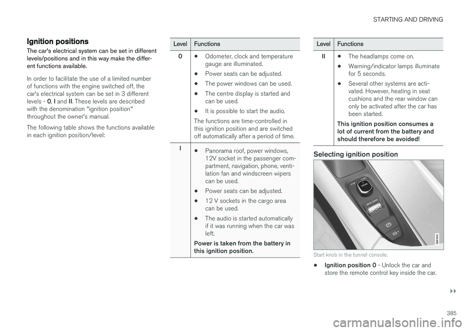
Start knob in the tunnel console.
• Ignition position 0
- Unlock the car and
store the remote control key inside the car.
Page 417 of 594
STARTING AND DRIVING
}}
* Option/accessory.415
Related information
•Driving with a trailer under special conditions (p. 428)
• Preparations for a long trip (p. 415)
Overloading the starter battery
The electrical functions in the car load the starter battery to varying degrees. Avoid using the igni-tion position II when the car is switched off.
Instead, use ignition position I - which uses less
power.
Also, be aware of different accessories that load the electrical system. Do not use functions whichuse a lot of power when the car is switched off.Examples of such functions are:
• ventilation fan
• headlamps
• windscreen wiper
• audio system (high volume).
If the starter battery voltage is low, the message
12 V Battery Low charge, will soon enter
power save mode is shown in the driver display.
The energy-saving function then shuts down cer- tain functions or reduces certain functions suchas the ventilation fan and/or audio system.
–In which case, charge the starter battery by starting the car and then running it for atleast 15 minutes - starter battery charging ismore effective during driving than runningthe engine at idling speed while stationary.
Related information
• Ignition positions (p. 385)
• Starter battery (p. 530)
Preparations for a long trip
Before a driving holiday or some other type of long journey, it is important to check the car'sfunctions and equipment particularly carefully.
Check that:
• the engine is working normally and that fuel consumption is normal
• there are no leaks (fuel, oil or other fluid)
• all bulbs are working
• the tyres have sufficient tread depth andpressure
• a warning triangle and high-visibility vest arelocated in the car - legally required in certaincountries
• the wiper blades are in good condition.
Related information
•
Fuel consumption and CO2 emissions(p. 572)
• Checking the tyre pressures (p. 484)
• Filling washer fluid (p. 529)
• Winter driving (p. 416)
• Economical driving (p. 422)
• Settings for car modem
* (p. 468)
• Loading (p. 227)
• Pilot Assist
* (p. 304)
• Speed limiter
* (p. 277)
Page 522 of 594
MAINTENANCE AND SERVICE
520
Servicing the climate control system The air conditioning system must only be serv- iced and repaired by an authorised workshop.
Troubleshooting and repairThe air conditioning system contains fluorescent tracing agents. Ultraviolet light must be used dur-ing leak detection. Volvo recommends that you contact an author- ised Volvo workshop.
Cars with R134a refrigerant
WARNING
The air conditioning system contains pressur- ised refrigerant R134a. This system must onlybe serviced and repaired by an authorisedworkshop.
Cars with R1234yf refrigerant
WARNING
The air conditioning system contains pressur- ised refrigerant R1234yf. In accordance withSAE J2845 (Technician Training for SafeService and Containment of RefrigerantsUsed in Mobile A/C System), service andrepair of the refrigerant system must only beperformed by trained and certified techniciansin order to ensure the safety of the system.
Related information
•Volvo service programme (p. 506)
Bulb replacement
The bulb in the halogen headlamp, reversing lamp and rear fog lamp can be replaced by thedriver.
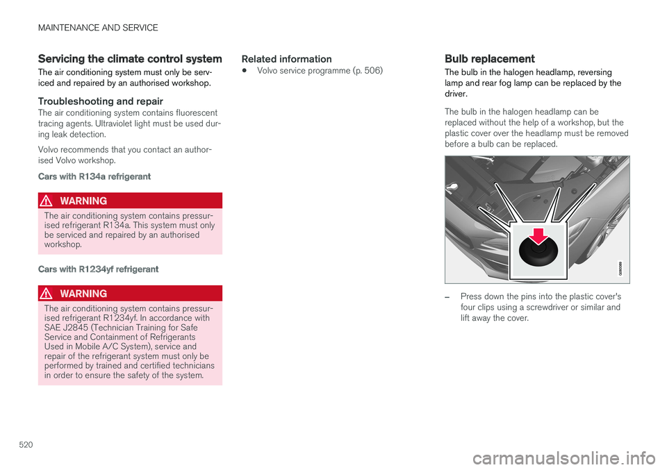
The bulb in the halogen headlamp can be replaced without the help of a workshop, but theplastic cover over the headlamp must be removedbefore a bulb can be replaced.
–Press down the pins into the plastic cover's four clips using a screwdriver or similar andlift away the cover.
Page 523 of 594
MAINTENANCE AND SERVICE
}}
* Option/accessory.521
NOTE
Points to remember when the cover is refit- ted: •The pin in the clip needs to be pressed back fully before the clip is refitted in thecover.
• When the cover is refitted, the pin mustbe pressed in until the end surface islevel with the surface of the clip.
The reversing lamp bulb and the rear fog lamp bulb can be replaced without assistance from aworkshop. Contact a workshop 9
if there is a fault in bulbs
other than the bulbs in the halogen headlamps, the reversing lamp bulb or the rear fog lamp bulb. If a fault occurs in LED 10
lamps, the entire lamp
unit usually must be replaced.
WARNING
The car's electrical system must be in ignition position 0 when replacing bulbs.
IMPORTANT
Never touch the glass part of the bulbs with your fingers. Grease from your fingers isvaporised by the heat, coating the reflectorand then causing damage.
NOTE
If an error message remains after the broken bulb has been replaced then we recommendvisiting an authorised Volvo workshop.
NOTE
Outside lighting such as headlamps and rear lamps may temporarily have condensation onthe inside of the lens. This is normal, all exte-rior lighting is designed to withstand this.Condensation is normally vented out of thelamp housing when the lamp has beenswitched on for a time.
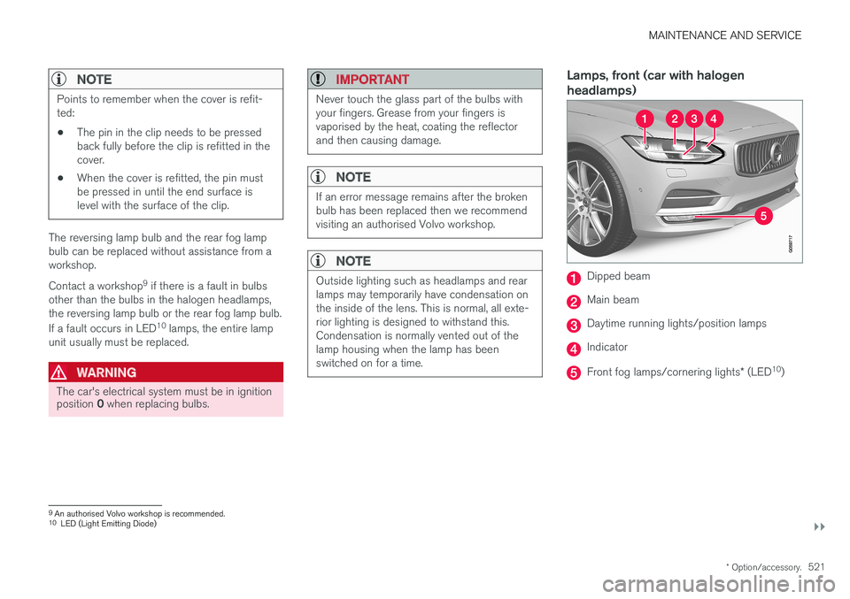
Lamps, front (car with halogen headlamps)
Dipped beam
Main beam
Daytime running lights/position lamps
Indicator
Front fog lamps/cornering lights * (LED 10
)
9An authorised Volvo workshop is recommended.
10 LED (Light Emitting Diode)
Page 524 of 594
||
MAINTENANCE AND SERVICE
522
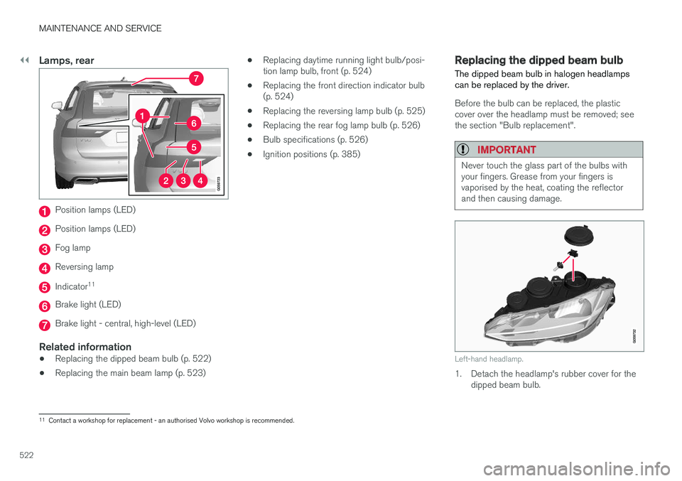
Lamps, rear
Position lamps (LED)
Position lamps (LED)
Fog lamp
Reversing lamp
Indicator11
Brake light (LED)
Brake light - central, high-level (LED)
Related information
•
Replacing the dipped beam bulb (p. 522)
• Replacing the main beam lamp (p. 523) •
Replacing daytime running light bulb/posi- tion lamp bulb, front (p. 524)
• Replacing the front direction indicator bulb(p. 524)
• Replacing the reversing lamp bulb (p. 525)
• Replacing the rear fog lamp bulb (p. 526)
• Bulb specifications (p. 526)
• Ignition positions (p. 385)
Replacing the dipped beam bulb
The dipped beam bulb in halogen headlamps can be replaced by the driver.
Before the bulb can be replaced, the plastic cover over the headlamp must be removed; seethe section "Bulb replacement".
IMPORTANT
Never touch the glass part of the bulbs with your fingers. Grease from your fingers isvaporised by the heat, coating the reflectorand then causing damage.
Left-hand headlamp.
1. Detach the headlamp's rubber cover for the dipped beam bulb.
11Contact a workshop for replacement - an authorised Volvo workshop is recommended.
Page 525 of 594

MAINTENANCE AND SERVICE
523
2. Unplug the connector from the bulb.
3. Detach the bulb by pushing it gently upwards
and pulling it straight out.
4. Fit a new bulb in the socket. The bulb's guide pin must be aimed straight upwards.
5. Press in the connector.
6. Refit the headlamp's rubber cover.
Related information
• Bulb replacement (p. 520)
• Bulb specifications (p. 526)
Replacing the main beam lamp
The main beam lamp in halogen headlamps can be replaced by the driver.
Before the bulb can be replaced, the plastic cover over the headlamp must be removed; seethe section "Bulb replacement".
IMPORTANT
Never touch the glass part of the bulbs with your fingers. Grease from your fingers isvaporised by the heat, coating the reflectorand then causing damage.
Left-hand headlamp.
1. Detach the headlamp's rubber cover for the main beam bulb.
2. Detach the bulb by turning the bulb holder upward and then pulling straight out. 3. Carefully prize the plastic cover at the con-
nector's lock lug so that the lock lug relea- ses.
4. Unplug the connector from the bulb.
5. Replace the bulb.
6. Fit the bulb in the socket and screw in.
7. Refit the headlamp's rubber cover.
Related information
• Bulb replacement (p. 520)
• Bulb specifications (p. 526)
Page 526 of 594

MAINTENANCE AND SERVICE
524
Replacing daytime running light bulb/position lamp bulb, front
The bulb for the daytime running light/position lamp in halogen headlamps can be replaced bythe driver.
Before the bulb can be replaced, the plastic
cover over the headlamp must be removed; see the section "Bulb replacement".
Left-hand headlamp.
1. Detach the headlamp's rubber cover for the daytime running light bulb/position lamp bulb.
NOTE
The bulb for the daytime running light/posi- tion lamp is easier to access if the main beambulb is detached. The main beam bulb is fitteddiagonally above the daytime running lightbulb/position lamp bulb. Detach the mainbeam bulb by rotating its bulb holder upwardsand then pulling straight out.
2. Pull the bulb holder for the daytime runninglight bulb/position lamp bulb straight out.
3. Detach the bulb by pulling it straight out.
4. Replace the bulb.
5. Fit the bulb holder into the socket and press it into place.
6. If the main beam bulb's bulb holder has been removed, fit it into the socket and screw in.
7. Refit the headlamp's rubber cover.
Related information
• Bulb replacement (p. 520)
• Bulb specifications (p. 526)
Replacing the front direction indicator bulb
The direction indicator bulb in halogen head- lamps can be replaced by the driver.
Before the bulb can be replaced, the plastic cover over the headlamp must be removed; seethe section "Bulb replacement".
Left-hand headlamp.
1. Detach the headlamp's rubber cover for the indicator bulb.
2. Press the catches together and pull the bulb holder straight out.
3. Replace with a new bulb holder with bulb.
4. Fit the bulb holder into the socket and press it into place.
5. Refit the headlamp's rubber cover.
Page 528 of 594
MAINTENANCE AND SERVICE
526
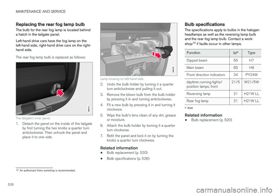
Replacing the rear fog lamp bulb The bulb for the rear fog lamp is located behind a hatch in the tailgate panel. Left-hand drive cars have the fog lamp on the left-hand side, right-hand drive cars on the right-hand side.
The rear fog lamp bulb is replaced as follows:
The tailgate's inner panel.
1. Detach the panel on the inside of the tailgateby first turning the two knobs a quarter turn anticlockwise. Then unhook the panel andplace it to one side.
Lamp housing on left-hand side.
2. Undo the bulb holder by turning it a quarterturn anticlockwise and pulling it out.
3. Remove the blown bulb from the bulb holder by pressing it in and turning anticlockwise.
4. Fit a new bulb by pressing it in and turning it clockwise.
5. Wipe the bulb's lens clean of any dirt, grease or moisture.
6. Attach the bulb holder by turning it a quarter turn clockwise.
7. Refit the panel and lock it on by turning the knobs a quarter turn clockwise.
Related information
• Bulb replacement (p. 520)
• Bulb specifications (p. 526)
Bulb specifications The specifications apply to bulbs in the halogen headlamps as well as the reversing lamp bulband the rear fog lamp bulb. Contact a work- shop 12
if faults occur in other lamps.
Function WA
Type
Dipped beam 55 H7
Main beam 65 H9
Front direction indicators 24 PY24Wdaytime running lights/ position lamps, front 21/5 W21/5W
Reversing lamp 21 H21W LL
Rear fog lamp 21 H21W LL
A Watt
Related information
• Bulb replacement (p. 520)
12
An authorised Volvo workshop is recommended.
Page 529 of 594
MAINTENANCE AND SERVICE
527
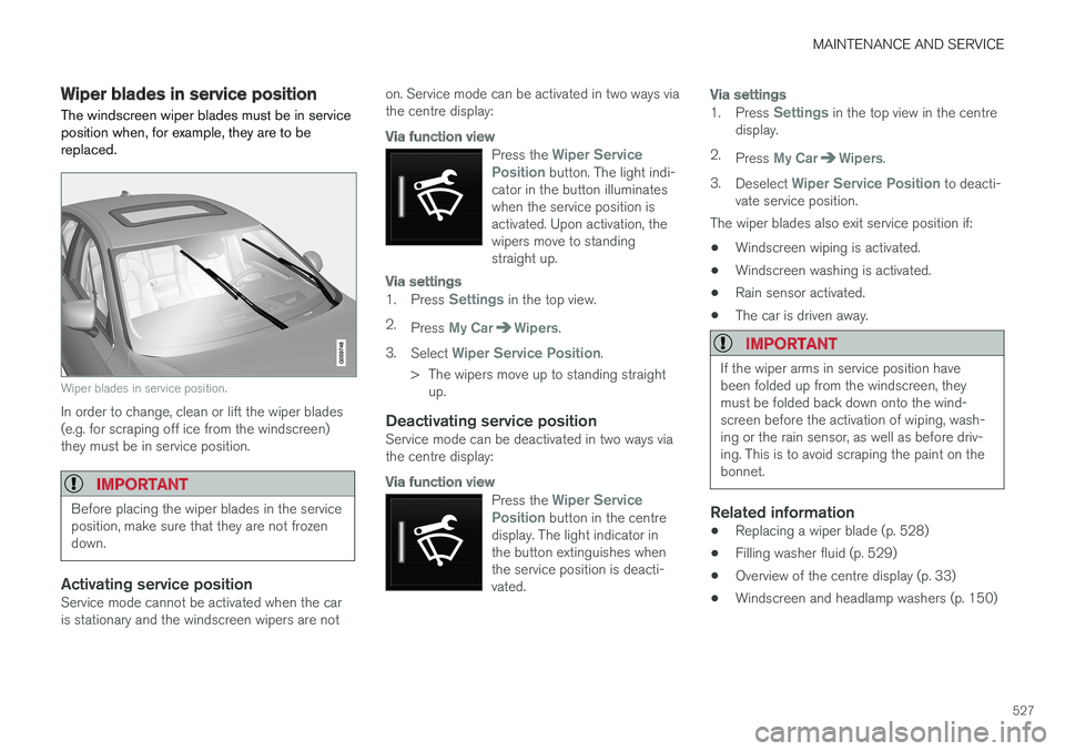
Wiper blades in service position The windscreen wiper blades must be in service position when, for example, they are to bereplaced.
Wiper blades in service position.
In order to change, clean or lift the wiper blades (e.g. for scraping off ice from the windscreen)they must be in service position.
IMPORTANT
Before placing the wiper blades in the service position, make sure that they are not frozendown.
Activating service positionService mode cannot be activated when the car is stationary and the windscreen wipers are noton. Service mode can be activated in two ways viathe centre display:
Via function view
Press the Wiper Service
Position button. The light indi-
cator in the button illuminates when the service position isactivated. Upon activation, thewipers move to standingstraight up.
Via settings
1. Press Settings in the top view.
2. Press
My CarWipers.
3. Select
Wiper Service Position.
> The wipers move up to standing straight up.
Deactivating service positionService mode can be deactivated in two ways via the centre display:
Via function view
Press the Wiper Service
Position button in the centre
display. The light indicator in the button extinguishes whenthe service position is deacti-vated.
Via settings
1. Press Settings in the top view in the centre
display.
2. Press
My CarWipers.
3. Deselect
Wiper Service Position to deacti-
vate service position.
The wiper blades also exit service position if:
• Windscreen wiping is activated.
• Windscreen washing is activated.
• Rain sensor activated.
• The car is driven away.
IMPORTANT
If the wiper arms in service position have been folded up from the windscreen, theymust be folded back down onto the wind-screen before the activation of wiping, wash-ing or the rain sensor, as well as before driv-ing. This is to avoid scraping the paint on thebonnet.
Related information
• Replacing a wiper blade (p. 528)
• Filling washer fluid (p. 529)
• Overview of the centre display (p. 33)
• Windscreen and headlamp washers (p. 150)