rear view mirror VOLVO XC60 2009 Owner´s Manual
[x] Cancel search | Manufacturer: VOLVO, Model Year: 2009, Model line: XC60, Model: VOLVO XC60 2009Pages: 297, PDF Size: 21.16 MB
Page 24 of 297
01 SafetyOccupant Weight Sensor 01
22 General information
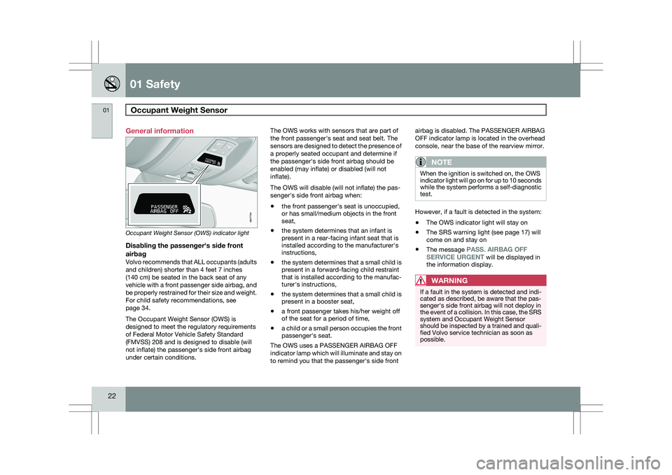
Occupant Weight Sensor (OWS) indicator light
Disabling the passenger\fs side front
airbag
Volvo recommends that ALL occupants (adults
and children) shorter than 4 feet 7 inches
(140 cm) be seated in the back seat of any
vehicle with a front passenger side airbag, and
be properly restrained for their size and weight.
For child safety recommendations, see
page 34.
The Occupant Weight Sensor (OWS) is
designed to meet the regulatory requirements
of Federal Motor Vehicle Safety Standard
(FMVSS) 208 and is designed to disable (will
not inflate) the passenger\fs side front airbag
under certain conditions. The OWS works with sensors that are part of
the front passenger\fs seat and seat belt. The
sensors are designed to detect the presence of
a properly seated occupant and determine if
the passenger\fs side front airbag should be
enabled (may inflate) or disabled (will not
inflate).
The OWS will disable (will not inflate) the pas-
senger\fs side front airbag when:
\b
the front passenger\fs seat is unoccupied,
or has small/medium objects in the front
seat,
\b the system determines that an infant is
present in a rear-facing infant seat that is
installed according to the manufacturer\fs
instructions,
\b the system determines that a small child is
present in a forward-facing child restraint
that is installed according to the manufac-
turer\fs instructions,
\b the system determines that a small child is
present in a booster seat,
\b a front passenger takes his/her weight off
of the seat for a period of time,
\b a child or a small person occupies the front
passenger\fs seat.
The OWS uses a PASSENGER AIRBAG OFF
indicator lamp which will illuminate and stay on
to remind you that the passenger\fs side front airbag is disabled. The PASSENGER AIRBAG
OFF indicator lamp is located in the overhead
console, near the base of the rearview mirror.
NOTE
When the ignition is switched on, the OWS
indicator light will go on for up to 10 seconds
while the system performs a self-diagnostic
test.
However, if a fault is detected in the system:
\b
The OWS indicator light will stay on
\b The SRS warning light (see page 17) will
come on and stay on
\b The message
PASS. AIRBAG OFF
SERVICE URGENT will be displayed in
the information display.
WARNING If a fault in the system is detected and indi-
cated as described, be aware that the pas-
senger\fs side front airbag will not deploy in
the event of a collision. In this case, the SRS
system and Occupant Weight Sensor
should be inspected by a trained and quali-
fied Volvo service technician as soon as
possible. 2
2
G017724
Page 37 of 297
01 Safety
Child restraint systems01
}}
35
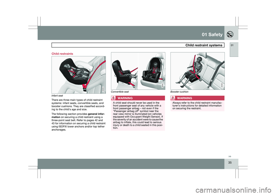
Child restraints
Infant seat
There are three main types of child restraint
systems: infant seats, convertible seats, and
booster cushions. They are classified accord-
ing to the child\fs age and size.
The following section provides
general infor-
mation on securing a child restraint using a
three-point seat belt. Refer to pages 42 and
43 for information on securing a child restraint
using ISOFIX lower anchors and/or top tether
anchorages. Convertible seat
WARNING
A child seat should never be used in the
front passenger seat of any vehicle with a
front passenger airbag – not even if the
"Passenger airbag off" symbol near the
rear-view mirror is illuminated (on vehicles
equipped with Occupant Weight Sensor). If
the severity of an accident were to cause the
airbag to inflate, this could lead to serious
injury or death to a child seated in this posi-
tion. Booster cushionWARNING
Always refer to the child restraint manufac-
turer\fs instructions for detailed information
on securing the restraint. G022840 G022847 G023269
Page 39 of 297
01 Safety
Infant seats01
}}
37
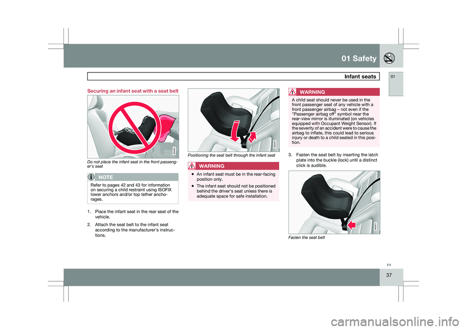
Securing an infant seat with a seat belt
Do not place the infant seat in the front passeng-
er's seat
NOTE
Refer to pages 42 and 43 for information
on securing a child restraint using ISOFIX
lower anchors and/or top tether ancho-
rages.
1.
Place the infant seat in the rear seat of the
vehicle.
2. Attach the seat belt to the infant seat according to the manufacturer\fs instruc-
tions. Positioning the seat belt through the infant seat
WARNING
\b
An infant seat must be in the rear-facing
position only.
\b The infant seat should not be positioned
behind the driver\fs seat unless there is
adequate space for safe installation.
WARNING A child seat should never be used in the
front passenger seat of any vehicle with a
front passenger airbag – not even if the
"Passenger airbag off" symbol near the
rear-view mirror is illuminated (on vehicles
equipped with Occupant Weight Sensor). If
the severity of an accident were to cause the
airbag to inflate, this could lead to serious
injury or death to a child seated in this posi-
tion.
3. Fasten the seat belt by inserting the latch
plate into the buckle (lock) until a distinct
click is audible. Fasten the seat belt G022844 G023270 G023271
Page 42 of 297
01 SafetyConvertible seats 01
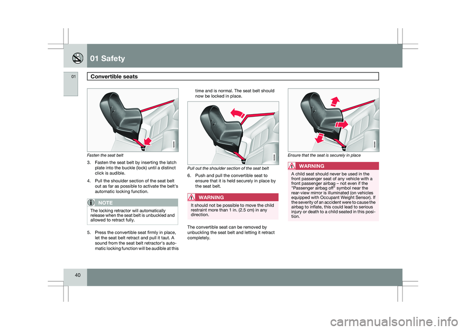
40 Fasten the seat belt
3. Fasten the seat belt by inserting the latch
plate into the buckle (lock) until a distinct
click is audible.
4. Pull the shoulder section of the seat belt out as far as possible to activate the belt\fs
automatic locking function.
NOTE The locking retractor will automatically
release when the seat belt is unbuckled and
allowed to retract fully.
5. Press the convertible seat firmly in place,
let the seat belt retract and pull it taut. A
sound from the seat belt retractor\fs auto-
matic locking function will be audible at this time and is normal. The seat belt should
now be locked in place.
Pull out the shoulder section of the seat belt
6. Push and pull the convertible seat to
ensure that it is held securely in place by
the seat belt.WARNING It should not be possible to move the child
restraint more than 1 in. (2.5 cm) in any
direction.
The convertible seat can be removed by
unbuckling the seat belt and letting it retract
completely. Ensure that the seat is securely in place
WARNING
A child seat should never be used in the
front passenger seat of any vehicle with a
front passenger airbag – not even if the
"Passenger airbag off" symbol near the
rear-view mirror is illuminated (on vehicles
equipped with Occupant Weight Sensor). If
the severity of an accident were to cause the
airbag to inflate, this could lead to serious
injury or death to a child seated in this posi-
tion. G022848 G022849 G022850
Page 101 of 297
03 Your driving environment
Mirrors03
99
to the neutral position for electric retracting/
extending to work.
\b
Retract the mirrors with the L and R but-
tons.
\b Fold them out again with the
L and R but-
tons.
The mirrors are now reset in neutral position.
Home safe and approach lightingThe light on the door mirrors comes on when
approach lighting or home safe lighting is
selected, see page 91.
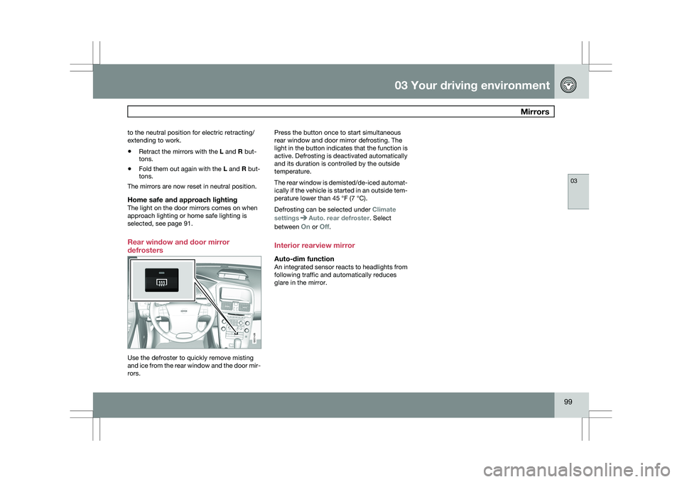
Rear window and door mirror
defrosters Use the defroster to quickly remove misting
and ice from the rear window and the door mir-
rors. Press the button once to start simultaneous
rear window and door mirror defrosting. The
light in the button indicates that the function is
active. Defrosting is deactivated automatically
and its duration is controlled by the outside
temperature.
The rear window is demisted/de-iced automat-
ically if the vehicle is started in an outside tem-
perature lower than 45 °F (7 °C).
Defrosting can be selected under
Climate
settings Auto. rear defroster. Select
between On or Off.
Interior rearview mirror
Auto-dim functionAn integrated sensor reacts to headlights from
following traffic and automatically reduces
glare in the mirror. G031426
Page 102 of 297
03 Your driving environmentPower panorama moonroof* 03
100
* Option/accessory, for more information, see Introduction.
Introduction
The panorama moonroof is divided into two
sections.
\b
The rear glass section is fixed in place and
cannot be moved.
\b The front glass section can be slid hori-
zontally to the open or closed positions or
its rear edge can be raised and lowered to
allow ventilation.
All references in this section to opening or clos-
ing the panorama moonroof pertain to the front
glass section.
The panorama moonroof also has a sun shade
made of perforated fabric that is located below
the sections of glass. This shade can be
opened or closed, for example when driving in
bright sunlight.
Both the panorama moonroof and the sun
shade are operated by the controls in the ceil-
ing console, near the rear-view mirror. The
vehicle\fs ignition must be in mode I or II before
the moonroof/sun shade can be operated.
CAUTION \b
Remove ice and snow before opening
the moonroof.
\b Do not operate the moonroof if it is fro-
zen closed.
\b Never place heavy objects on the
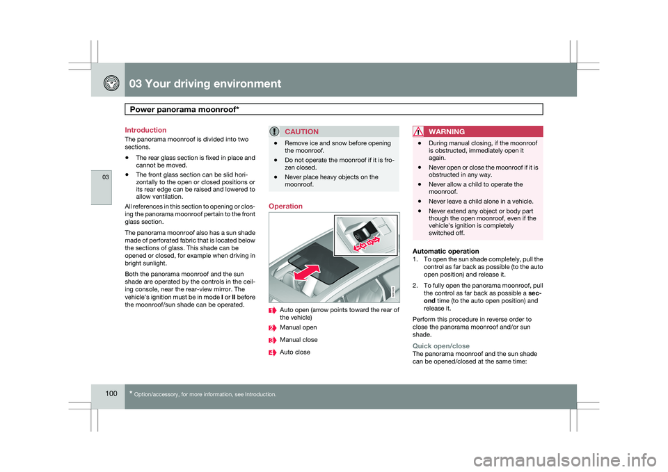
moonroof. Operation
Auto open (arrow points toward the rear of
the vehicle)
Manual open
Manual close
Auto closeWARNING \b
During manual closing, if the moonroof
is obstructed, immediately open it
again.
\b Never open or close the moonroof if it is
obstructed in any way.
\b Never allow a child to operate the
moonroof.
\b Never leave a child alone in a vehicle.
\b Never extend any object or body part
though the open moonroof, even if the
vehicle\fs ignition is completely
switched off.
Automatic operation1.
To open the sun shade completely, pull the
control as far back as possible (to the auto
open position) and release it.
2. To fully open the panorama moonroof, pull
the control as far back as possible a sec-
ond time (to the auto open position) and
release it.
Perform this procedure in reverse order to
close the panorama moonroof and/or sun
shade.
Quick open/closeThe panorama moonroof and the sun shade
can be opened/closed at the same time: G031428
Page 128 of 297
04 Comfort and driving pleasureClimate system 04
126
* Option/accessory, for more information, see Introduction.
Introduction
Air conditioningThe vehicle is equipped with Electronic Climate
Control (ECC). The climate control system
cools, heats or dehumidifies the air in the pas-
senger compartment.
NOTE
\b
The air conditioning can be switched
off, but to ensure the best possible cli-
mate comfort in the passenger com-
partment and to prevent the windows
from misting, it should always be on.
\b In warm weather, a small amount of
water may accumulate under the car
when it has been parked. This water is
condensation from the A/C system and
is normal.
Sensor location
\b
The sunlight sensor is located on the top
side of the dashboard.
NOTE The sunlight sensor monitors which side of
the car that is most exposed to sunlight.
This can mean that the temperature may
differ between the right and left-side air
vents, even if the temperatures set for both
sides of the passenger compartment are the
same.
\b
The temperature sensor for the passenger
compartment is located below the climate
control panel.
\b The outside temperature sensor is located
on the door mirror.
\b The humidity sensor
* is located in the inte-
rior rearview mirror.
NOTE Do not cover or block the sensors with
clothing or other objects.
Side windows and moonroofTo ensure that the air conditioning works opti-
mally, the side windows, and the optional
moonroof should be closed.
Fog on the inside of the windowsThe defroster function should be used to
remove fog or mist from the inside of the win-
dows. Keeping the windows clean with a com-mercially available window washing spray will
also help prevent fogging or misting.
Temporary shut-off of the air
conditioning
The air conditioning is momentarily disen-
gaged during full-throttle acceleration or when
driving uphill with a trailer. This may result in a
temporary increase in cabin temperature.
Ice and snowAlways keep the air intake grille at the base of
the windshield free of snow.
Climate system maintenanceSpecial tools and equipment are required to
maintain and carry out repairs on the climate
system. Work of this type should only be done
by a trained and qualified Volvo service tech-
nician.
RefrigerantVolvo cares about the environment. The air
conditioning system in your car contains a
CFC-free refrigerant – R134a. This substance
will not deplete the ozone layer. The air condi-
tioning system contains 1.8 lbs (800 g) of
R134a. The systems uses PAG oil.
Passenger compartment filterReplace the cabin air filter with a new one at
the recommended intervals. Please refer to
Page 156 of 297
04 Comfort and driving pleasureCompass 04
154 Operation
Rearview mirror with compass.
The rearview mirror has an integrated display
that shows the compass direction in which the
vehicle is pointing. Eight different directions
are shown with the abbreviations: N (north),
NE (north east), E (east), SE (southeast), S
(south), SW (southwest), W (west) and NW
(northwest).
The compass is displayed automatically when
the vehicle is started or in ignition mode II. To
switch the compass on/off use a pen or similar
object and press in the button on the rear side
of the mirror.
CalibrationThe compass may need to be calibrated if, for
example, the vehicle is driven into a new mag-
netic zone. 1.
Stop the vehicle in a large open area, safely
out of traffic and away from steel structures
and high-tension electrical wires.
2. Start the vehicle.
NOTE For best results from calibration, switch off
all electrical equipment in the vehicle (cli-
mate system, windshield wipers, audio sys-
tem, etc.) and make sure that all doors are
closed.
3. Using a pen or similar object, press and
hold the button on the rear side of mirror
until C is shown again in the mirror(after
approx. 6 seconds).
4. Drive as usual. C disappears from the dis-
play when calibration is complete.
Alternative calibration method:
Drive slowly in a circle at a speed of no
more than 5 mph (8 km/h) until C disap-
pears from the display when calibration is
complete.
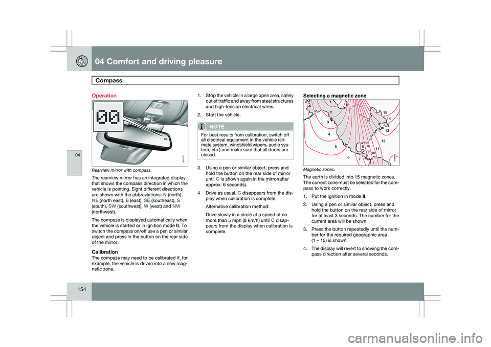
Selecting a magnetic zone Magnetic zones.
The earth is divided into 15 magnetic zones.
The correct zone must be selected for the com-
pass to work correctly.
1.
Put the ignition in mode II.
2. Using a pen or similar object, press and hold the button on the rear side of mirror
for at least 3 seconds. The number for the
current area will be shown.
3. Press the button repeatedly until the num-
ber for the required geographic area
(1 – 15) is shown.
4. The display will revert to showing the com-
pass direction after several seconds. G031611
15
14
13
12
1198
76
5
4
3
2
1
10
G018632
Page 193 of 297
04 Comfort and driving pleasure
Park Assist Camera (PAC)*04
}}
* Option/accessory, for more information, see Introduction. 191
DeactivationMove the gear selector from
R to another posi-
tion. There is a slight delay in the PAC system,
which means that the view from behind the
vehicle will remain on the screen for approxi-
mately 15 seconds after the gear selector has
been moved from the R position or until the
vehicle reaches a forward speed of 6 mph
(10 km/h). The screen will then revert to the
mode that it was in before R was selected and
will, for example, display navigation system
information.
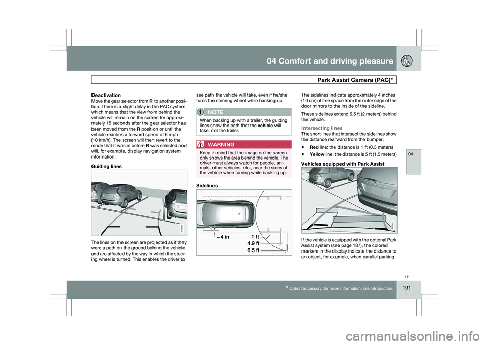
Guiding lines The lines on the screen are projected as if they
were a path on the ground behind the vehicle
and are affected by the way in which the steer-
ing wheel is turned. This enables the driver to see path the vehicle will take, even if he/she
turns the steering wheel while backing up.
NOTE When backing up with a trailer, the guiding
lines show the path that the vehicle will
take, not the trailer.
WARNING
Keep in mind that the image on the screen
only shows the area behind the vehicle. The
driver must always watch for people, ani-
mals, other vehicles, etc., near the sides of
the vehicle when turning while backing up.
Sidelines The sidelines indicate approximately 4 inches
(10 cm) of free space from the outer edge of the
door mirrors to the inside of the sideline.
These sidelines extend 6.5 ft (2 meters) behind
the vehicle.
Intersecting linesThe short lines that intersect the sidelines show
the distance rearward from the bumper.
\b
Red line: the distance is 1 ft (0.3 meters)
\b Yellow line: the distance is 5 ft (1.5 meters)
Vehicles equipped with Park Assist If the vehicle is equipped with the optional Park
Assist system (see page 187), the colored
markers in the display indicate the distance to
an object, for example, when parallel parking. G000000 G031931
Page 194 of 297
04 Comfort and driving pleasurePark Assist Camera (PAC)* 04
192
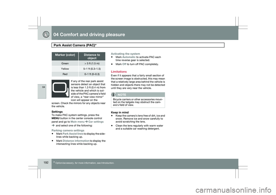
* Option/accessory, for more information, see Introduction. Marker (color) Distance to
object Green > 5 ft (1.5 m)
Yellow 5–1 ft (0.3–1.5)
Red 0–1 ft (0–0.3)
If any of the rear park assist
sensors detect an object that
is less than 1.3 ft (0.4 m) from
the vehicle and which is out-
side of the PAC camera’s field
of view, a “rear-view mirror”
icon will appear on the
screen. Check the mirrors for any objects near
the vehicle.
SettingsTo make PAC system settings, press the
MENU button in the center console control
panel and go to Main menu Car settings
and select one of the following:
Parking camera settings
\b
Mark Park Assist lines to display the side-
lines while backing up.
\b Mark Distance information to display the
intersecting lines while backing up.
Activating the system
\bMark Automatic to activate PAC each
time reverse gear is selected.
\b Mark Off to turn off PAC completely.
Limitations
Even if it appears that a fairly small section of
the screen image is obstructed, this may mean
that a relatively large area behind the vehicle is
hidden and objects there may not be detected
until they are very near the vehicle.
NOTE Bicycle carriers or other accessories moun-
ted on the tailgate may obstruct the cam-
era\fs field of view.
Keep in mind
\b
Keep the camera\fs lens free of dirt, ice and
snow. Remove ice and snow carefully to
avoid scratching the lens.
\b Clean the lens regularly with warm water
and a suitable car washing detergent.