tow VOLVO XC60 2015 Owner´s Manual
[x] Cancel search | Manufacturer: VOLVO, Model Year: 2015, Model line: XC60, Model: VOLVO XC60 2015Pages: 406, PDF Size: 11.03 MB
Page 6 of 406
Contents
4* Option/accessory, for more information, see Introduction.
06
06 Infotainment
Introduction............................................. 238
Radio....................................................... 248
Media player........................................... 257
AUX/USB sockets................................... 262 Bluetooth ®
media ................................... 265
Bluetooth ®
hands-free connection ........ 267
Cell phone voice control*........................ 276
07
07 During your trip
Driving recommendations....................... 282
Refueling................................................. 286
Loading................................................... 291
Cargo area ............................................. 295
Towing a trailer....................................... 299
Emergency towing.................................. 302
08
08 Wheels and tires
General information ............................... 306
Tire inflation............................................. 309
Inflation pressure ................................... 312
Tire designations .................................... 313
Glossary of tire terminology ................... 315
Vehicle loading ....................................... 316
Uniform Tire Quality Grading ................. 318
Snow chains, snow tires, studded tires . 319
Temporary Spare ................................... 320
Tire Sealing System*............................... 321
Changing a wheel .................................. 327
Tire Pressure Monitoring System (TPMS) 331
Page 24 of 406
01 Safety
Supplemental Restraint System (SRS) 01
22
WARNING
If your vehicle has become flood-damaged in any way (e.g., soaked carpeting/stand-ing water on the floor of the vehicle), donot attempt to start the vehicle or insertthe remote key into the ignition slot beforedisconnecting the battery (see below). Thismay cause airbag deployment which couldresult in serious injury. Have the vehicletowed to a trained and qualified Volvoservice technician for repairs. Before attempting to tow the vehicle:
1. Switch off the ignition for at least10 minutes and disconnect the bat- tery.
2. Follow the instructions for manually overriding the shiftlock system onpage 131.
Front airbags
G018665
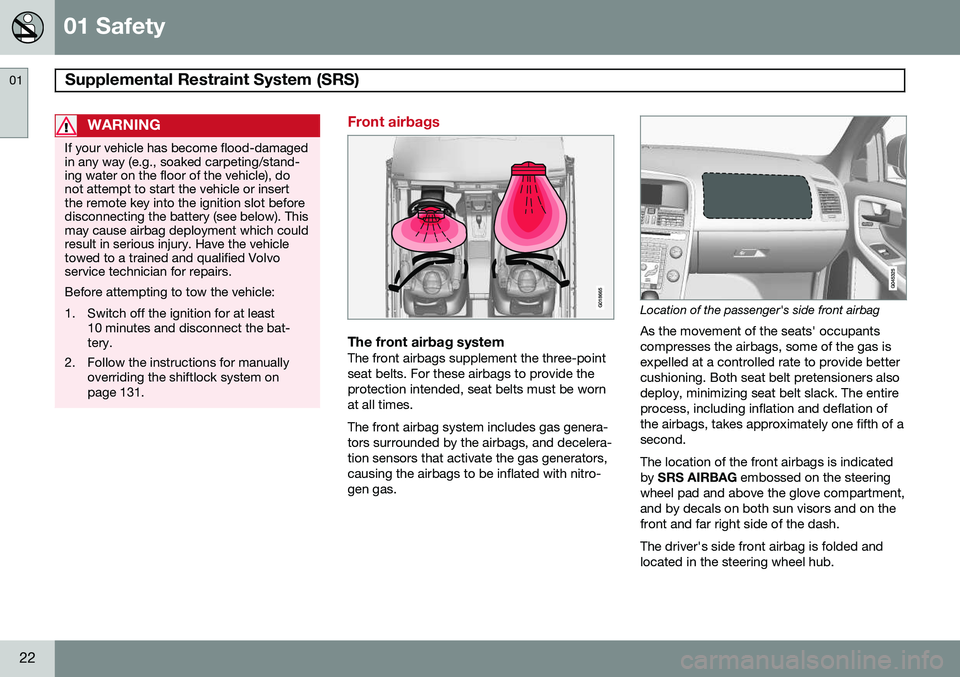
The front airbag systemThe front airbags supplement the three-point seat belts. For these airbags to provide theprotection intended, seat belts must be wornat all times. The front airbag system includes gas genera- tors surrounded by the airbags, and decelera-tion sensors that activate the gas generators,causing the airbags to be inflated with nitro-gen gas.
Location of the passenger's side front airbag
As the movement of the seats' occupants compresses the airbags, some of the gas isexpelled at a controlled rate to provide bettercushioning. Both seat belt pretensioners alsodeploy, minimizing seat belt slack. The entireprocess, including inflation and deflation ofthe airbags, takes approximately one fifth of asecond. The location of the front airbags is indicated by SRS AIRBAG embossed on the steering
wheel pad and above the glove compartment,and by decals on both sun visors and on thefront and far right side of the dash. The driver's side front airbag is folded and located in the steering wheel hub.
Page 27 of 406
01 Safety
Supplemental Restraint System (SRS)01
25
WARNING
•Children must never be allowed in the front passenger's seat.
• Occupants in the front passenger'sseat must never sit on the edge of theseat, sit leaning toward the instrumentpanel or otherwise sit out of position.
• The occupant's back must be asupright as comfort allows and beagainst the seat back with the seatbelt properly fastened.
• Feet must be on the floor, e.g., not onthe dash, seat or out of the window.
WARNING
•No objects or accessory equipment, e.g. dashboard covers, may be placedon, attached to, or installed near theair bag hatch (the area above the glovecompartment) or the area affected byairbag deployment (see the illustrationon page 22).
• There should be no loose articles,such as coffee cups on the floor, seat,or dashboard area.
• Never try to open the airbag cover onthe steering wheel or the passenger'sside dashboard. This should only bedone by a trained and qualified Volvoservice technician.
• Failure to follow these instructions canresult in injury to the vehicle occu-pants.
Page 29 of 406
01 Safety
Occupant Weight Sensor01
}}
27
WARNING
•Never try to open, remove, or repair any components in the OWS system.This could result in system malfunc-tion. Maintenance or repairs shouldonly be carried out by an a trained andqualified Volvo service technician.
• The front passenger's seat should notbe modified in any way. This couldreduce pressure on the seat cushion,which might interfere with the OWSsystem's function.
Passeng- er's seatoccu-pancy sta-tusOWS indicatorlight sta-tusPasseng- er's sidefront air-bag status
Seat unoc- cupiedOWS indi- cator lightlights up.Passenger's side front air-bag disabled
Seat occu- pied by lowweightoccupant/ object AOWS indi- cator lightlights upPassenger's side front air-bag disabled
Seat occu- pied byheavy occu-pant/objectOWS indi- cator lightis
not litPassenger's side front air-bag enabled
A
Volvo recommends that children always be properly restrained in appropriate child restraints in the rear seats.Do not assume that the passenger's side front airbag isdisabled unless the PASSENGER AIRBAG OFF indicatorlamp is lit. Make sure the child restraint is properly instal-led. If there is any doubt as to the status of the passeng-er's side front airbag, move the child restraint to the rearseat.
The OWS is designed to enable (may inflate) the passenger's side front airbag in the eventof a collision anytime the system senses thata person of adult size is sitting properly in thefront passenger's seat. The PASSENGER AIRBAG OFF indicator lamp will be off andremain off. If a person of adult size is sitting in the front passenger's seat, but the PASSENGER AIR-BAG OFF indicator lamp is on, it is possiblethat the person isn't sitting properly in theseat. If this happens:
• Turn the vehicle off and ask the person to place the seatback in an upright position.
• Have the person sit upright in the seat,centered on the seat cushion, with theperson's legs comfortably extended.
• Restart the vehicle and have the personremain in this position for about twominutes. This will allow the system todetect that person and enable the pas-senger's frontal airbag.
• If the PASSENGER AIRBAG OFF indica-tor lamp remains on even after this, theperson should be advised to ride in therear seat.
This condition reflects limitations of the OWS classification capability. It does not indicateOWS malfunction.
ModificationsIf you are considering modifying your vehiclein any way to accommodate a disability, forexample by altering or adapting the driver's
Page 39 of 406
01 Safety
Crash mode01
37
If the message
Safety mode See manual is
still displayed, the vehicle should not be driven and must be towed. Concealed faultsmay make the vehicle difficult to control.
Moving the vehicle
If the message Normal mode is displayed
when Safety mode See manual is no longer
displayed, the vehicle may be moved care- fully from its present position, if for example,it is blocking traffic. It should, however, notbe moved farther than is absolutely neces-sary.
WARNING
Even if the vehicle appears to be drivable after Safety mode has been set, it shouldnot be driven or towed (pulled by anothervehicle). There may be concealed damagethat could make it difficult or impossible tocontrol. The vehicle should be transportedon a flatbed tow truck to a trained andqualified Volvo service technician forinspection/repairs.
Page 54 of 406

01 Safety
Integrated booster cushion* 01
52* Option/accessory, for more information, see Introduction.
Integrated two-stage booster cushion 1
Volvo's optional integrated booster cushions are located in the outboard seating positions.These booster cushions have been speciallydesigned to help safeguard children in therear seat. They should be stowed (foldeddown into the seat cushion) when not in use.When using an integrated booster cushion,the child must be secured with the vehicle'sthree-point seat belt.
Use these booster cushions only with children whose weight isbetween: • Stage 1: 48 – 80 lbs (22 – 36 kg)
• Stage 2: 33 – 55 lbs (15 – 25 kg)
and whose height is between:• Stage 1: 45 – 55 in. (115 – 140 cm)
• Stage 2: 37 – 47 in. (95 – 120 cm)
In Canada, Transport Canada's weight recommendation is 40 – 80 lbs (18 – 36 kg). The booster cushions are designed to raise the child higher, so that the shoulder strapcrosses over the child's collarbone, not overthe child's neck. If using a booster cushiondoes not result in proper positioning of theshoulder strap, then the child should beplaced in a properly secured child restraint(see page 41). The shoulder belt must neverbe placed behind the child's back or underthe arm.
Correct seating position: child's head is below the head restraint and the shoulder belt is acrossthe collarbone
Incorrect seating position: the child's head is above the head restraint and the shoulder belt isnot across the collarbone Before driving, check that:
• The integrated two-stage booster cushion is set in the correct position according tothe child's height and weight (see thetable below) and is locked in position.
Stage 1Stage 2
Weight48 – 80 lbs 22 – 36 kg33 – 55 lbs 15 – 25 kg
Height45 – 55 in. 115 – 140 cm37 – 47 in. 95 – 120 cm
1
Canada only: This cushion may be referred to as a built-in booster cushion.
Page 55 of 406

01 Safety
Integrated booster cushion*01
}}
* Option/accessory, for more information, see Introduction.53
•
That the seat belt is properly positioned and is taut.
• The shoulder section of the seat belt isacross the child's collarbone, not over theneck.
• The lap section of the seat belt is acrossthe child's hips and not the abdomen.
Using an integrated booster cushion
Stage 1
Pull the handle (1) forward and upward (2) to release the booster cushion.
Press the booster cushion rearward to lock it in position.
Stage 2
With the booster cushion in the stage 1 position, press the button (see the arrowin illustration 1).
Lift the front edge of the booster cushion and press it rearward toward the backrestto lock it in position.
Page 56 of 406
01 Safety
Integrated booster cushion* 01
54* Option/accessory, for more information, see Introduction.
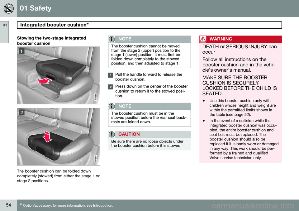
Stowing the two-stage integrated booster cushion
The booster cushion can be folded down completely (stowed) from either the stage 1 orstage 2 positions.
NOTE
The booster cushion cannot be moved from the stage 2 (upper) position to thestage 1 (lower) position. It must first befolded down completely to the stowedposition, and then adjusted to stage 1.
Pull the handle forward to release the booster cushion.
Press down on the center of the booster cushion to return it to the stowed posi-tion.
NOTE
The booster cushion must be in the stowed position before the rear seat back-rests are folded down.
CAUTION
Be sure there are no loose objects under the booster cushion before it is stowed.
WARNING
DEATH or SERIOUS INJURY can occur Follow all instructions on the booster cushion and in the vehi-cle's owner's manual. MAKE SURE THE BOOSTER CUSHION IS SECURELYLOCKED BEFORE THE CHILD ISSEATED. • Use this booster cushion only with children whose height and weight arewithin the permitted limits shown inthe table (see page 52).
• In the event of a collision while theintegrated booster cushion was occu-pied, the entire booster cushion andseat belt must be replaced. Thebooster cushion should also bereplaced if it is badly worn or damagedin any way. This work should be per-formed by a trained and qualifiedVolvo service technician only.
Page 60 of 406

02 Locks and alarm
Remote key and key blade
02
58
Introduction
Two remote keys or optional Personal Car Communicators (PCC) are provided with yourvehicle. They enable you to unlock the doorsand tailgate, and also function as ignitionkeys to start the vehicle or operate electricalcomponents. The remote keys containdetachable metal key blades for manuallylocking or unlocking the driver's door and theglove compartment. The visible ends of thesekey blades are unique to make it easier toidentify "your" remote key. Up to six remotescan be programmed for use on the samevehicle. The PCCs have enhanced functionality com- pared with the standard remote key.
NOTE
In the remainder of this chapter, all refer- ences to the remote key also pertain to thePCC unless otherwise stated.
WARNING
Never leave the remote key in the ignition slot if children are to remain in the vehicle.
See page 88 for more information on the various ignition modes.
Detachable key bladeEach remote key or PCC contains a detacha-ble metal key blade for mechanically lockingor unlocking the driver's door and the glovecompartment. See page 64 for more infor-mation on the key blade. The key blades havea unique code, which is used if new onesneed to be produced. This code is availableat an authorized Volvo retailer. The visible ends of these key blades are unique to make it easier to identify "your"remote key.
Loss of a remote keyIf either of the remote keys is lost, the othershould be taken with the car to a Volvoretailer. As an anti-theft measure, the code ofthe lost remote key must be erased from thesystem.
NOTE
Additional or duplicate remote control keys can be obtained from any AuthorizedVolvo Retailer. You can also obtain additional or duplicate remote control keys from certain inde-pendent repair facilities and locksmithsthat are qualified to make remote controlkeys. Each key must be programmed towork with your vehicle. California Only: A list of independent repair facilities and/or locksmiths known to Volvo that can cutand code replacement keys can be found:
• on the Volvo website at http://www.volvocars.com/us/keys
• by calling Volvo Customer Care at1-800-458-1552
The number of registered keys for the vehicle can be found by pressing
MY CAR and going
into
SettingsInformationNumber of
keys. See page 209 for a description of the
menu system. USA-5WK49264FCC ID:KR55WK49264 + Siemens VDO 5WK49236 FCC ID:KR55WK49236, 5WK49266
Page 86 of 406

03 Your driving environment
Instruments and controls
03
84
SymbolDescription
SRS airbags
Seat belt reminder
Generator not charging
Fault in the brake system
Warning symbol, read the text displayed in the instrumentpanel
Low oil pressure
If the light comes on while driving, stop the vehicle, stop the engine immediately, andcheck the engine oil level. Add oil if neces-sary. If the oil level is normal and the lightstays on after restart, have the vehicle towedto the nearest trained and qualified Volvoservice technician.
Parking brake applied
This symbol flashes while the brake is being applied and then glows steadily when theparking brake has been set. See page 145 for more information about using the parking brake.
Airbags – SRS
If this light comes on while the vehicle is being driven, or remains on for longer thanapproximately 10 seconds after the vehiclehas been started, the SRS system's diagnos-tic functions have detected a fault in a seatbelt lock or pretensioner, a front airbag, sideimpact airbag, and/or an inflatable curtain.Have the system(s) inspected by a trainedand qualified Volvo service technician assoon as possible. See page 21 for more information about the airbag system.
Seat belt reminder
This symbol comes on for approximately 6 seconds if the driver has not fastened his orher seat belt.
Generator not charging
This symbol comes on during driving if a fault has occurred in the electrical system. Contactan authorized Volvo workshop.
Engine temperatureEngine overheating can result from low oil or coolant levels, towing or hard driving at highheat and altitude, or mechanical malfunction.Engine overheating will be signaled with textand a red warning triangle in the middle of theinstrument display. The exact text will dependon the degree of overheating. It may rangefrom
High engine temp Reduce speed toHigh engine temp Stop engine. If appropri-
ate, other messages, such as Coolant level
low, Stop safely will also be displayed. If
your engine does overheat so that you must stop the engine, always allow the engine tocool before attempting to check oil and cool-ant levels. See page 346 for more information.
Fault in brake system
If this symbol lights, the brake fluid level may be too low. Stop the vehicle in a safe placeand check the level in the brake fluid reser-voir, see page 346. If the level in the reservoiris below MIN, the vehicle should be transpor-
ted to an authorized Volvo workshop to havethe brake system checked. If the
and symbols come on
at the same time, there may be a fault in the brake force distribution system.
1. Stop the vehicle in a safe place and turn off the engine.
2. Restart the engine.
• If both symbols extinguish, continue driv- ing.
• If the symbols remain on, check the levelin the brake fluid reservoir, see page 346.If the brake fluid level is normal but the