VOLVO XC60 2017 Owner´s Manual
Manufacturer: VOLVO, Model Year: 2017, Model line: XC60, Model: VOLVO XC60 2017Pages: 398, PDF Size: 9.17 MB
Page 111 of 398
INSTRUMENTS AND CONTROLS
}}
* Option/accessory, for more information, see Introduction.109
Panoramic roof* – operation
The laminated panoramic roof is divided into two sections. The rear glass section is fixed in placeand cannot be moved but the front glass sectioncan be slid horizontally to the open or closedpositions or its rear edge can be raised and low-ered to allow ventilation.
Operation
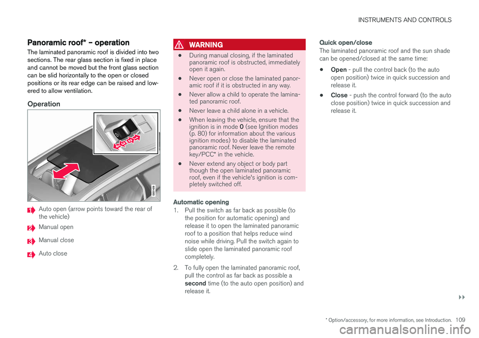
Auto open (arrow points toward the rear of the vehicle)
Manual open
Manual close
Auto close
WARNING
• During manual closing, if the laminated panoramic roof is obstructed, immediatelyopen it again.
• Never open or close the laminated panor-amic roof if it is obstructed in any way.
• Never allow a child to operate the lamina-ted panoramic roof.
• Never leave a child alone in a vehicle.
• When leaving the vehicle, ensure that the ignition is in mode
0 (see Ignition modes
(p. 80) for information about the various ignition modes) to disable the laminatedpanoramic roof. Never leave the remote key/PCC * in the vehicle.
• Never extend any object or body part though the open laminated panoramicroof, even if the vehicle's ignition is com-pletely switched off.
Automatic opening
1. Pull the switch as far back as possible (to
the position for automatic opening) and release it to open the laminated panoramicroof to a position that helps reduce windnoise while driving. Pull the switch again toslide open the laminated panoramic roofcompletely.
2. To fully open the laminated panoramic roof, pull the control as far back as possible a second time (to the auto open position) and
release it.
Quick open/close
The laminated panoramic roof and the sun shade can be opened/closed at the same time: • Open
- pull the control back (to the auto
open position) twice in quick succession and release it.
• Close
- push the control forward (to the auto
close position) twice in quick succession andrelease it.
Page 112 of 398
||
INSTRUMENTS AND CONTROLS
110
Manual operation
1.Opening the sun shade : Pull the control
back to the first stop (the manual open posi- tion) and hold it until the sun shade hasopened to the position of your choice.
2. Opening the rear edge of the laminatedpanoramic roof : Pull the control back to the
first stop (the manual open position) a sec-
ond time to open the rear edge of the lami-
nated panoramic roof.
3. Opening the front glass section : Pull the
control back to the first stop (the manual open position) a third time and hold it until
the laminated panoramic roof has opened to the position of your choice.
Perform this procedure in reverse order to closethe laminated panoramic roof and/or sun shade.
NOTE
For manual opening, the sun shade must first be fully open before it will be possible to openthe laminated panoramic roof. When closing,the laminated panoramic roof must be fullyclosed before the sun shade can be closed.
Tilt position
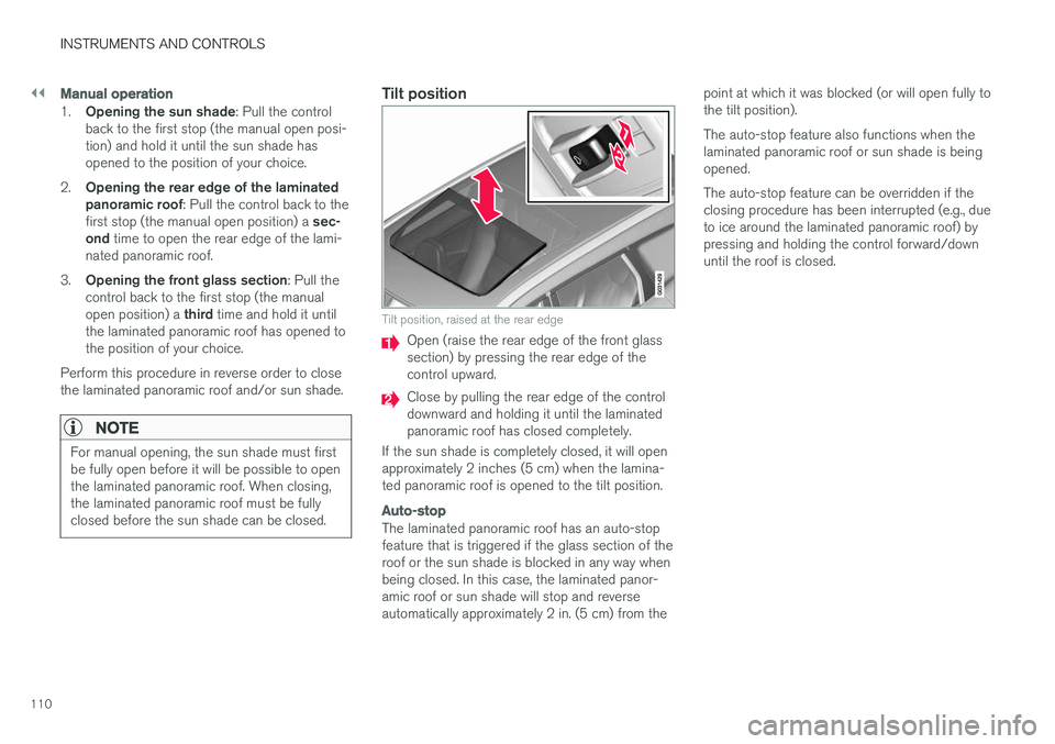
Tilt position, raised at the rear edge
Open (raise the rear edge of the front glass section) by pressing the rear edge of thecontrol upward.
Close by pulling the rear edge of the control downward and holding it until the laminatedpanoramic roof has closed completely.
If the sun shade is completely closed, it will openapproximately 2 inches (5 cm) when the lamina-ted panoramic roof is opened to the tilt position.
Auto-stop
The laminated panoramic roof has an auto-stop feature that is triggered if the glass section of theroof or the sun shade is blocked in any way whenbeing closed. In this case, the laminated panor-amic roof or sun shade will stop and reverseautomatically approximately 2 in. (5 cm) from the point at which it was blocked (or will open fully tothe tilt position). The auto-stop feature also functions when the laminated panoramic roof or sun shade is beingopened. The auto-stop feature can be overridden if the closing procedure has been interrupted (e.g., dueto ice around the laminated panoramic roof) bypressing and holding the control forward/downuntil the roof is closed.
Page 113 of 398
INSTRUMENTS AND CONTROLS
* Option/accessory, for more information, see Introduction.111
HomeLink®
Wireless Control
System * – introduction
HomeLink ®
can be used to open garage doors,
gates, etc.WARNING
• If you use HomeLink ®
to open a garage
door or gate, be sure no one is near the gate or door while it is in motion.
• When programming a garage dooropener, it is advised to park outside of thegarage.
• Do not use HomeLink ®
with any garage
door opener that lacks safety stop andreverse features as required by U.S. fed-eral safety standards (this includes anygarage door opener model manufacturedbefore April 1, 1982). A garage door thatcannot detect an object - signaling thedoor to stop and reverse - does not meetcurrent U.S. federal safety standards. Formore information, contact HomeLink at:www.homelink.com.
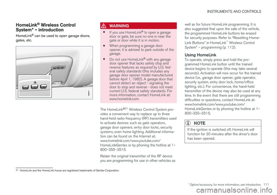
The HomeLink ®
21
Wireless Control System pro-
vides a convenient way to replace up to three hand-held radio-frequency (RF) transmitters usedto activate devices such as gate operators,garage door openers, entry door locks, securitysystems, even home lighting. Additional informa-tion can be found on the Internet at,www.homelink.com/www.youtube.com/HomeLinkGentex or by phoning the hotline at 1–800–355–3515. Retain the original transmitter of the RF device you are programming for use in other vehicles as well as for future HomeLink programming. It isalso suggested that upon the sale of the vehicle,the programmed HomeLink buttons be erasedfor security purposes. Refer to “Resetting Home- Link Buttons” in HomeLink
®
Wireless Control
System * – programming (p. 112).
Using HomeLinkTo operate, simply press and hold the pro- grammed HomeLink button until the traineddevice begins to operate (this may take severalseconds). Activation will now occur for the traineddevice (i.e., garage door opener, gate operator,security system, entry door lock, home/officelighting, etc.). For convenience, the hand-heldtransmitter of the device may also be used at anytime. In the event that there are still programmingdifficulties or questions, contact HomeLink at:www.homelink.com/www.youtube.com/HomeLinkGentex or by phoning the hotline at 1–800–355–3515.
NOTE
If the ignition is switched off, HomeLink will function for 30 minutes after the driver's doorhas been opened.
21
HomeLink and the HomeLink house are registered trademarks of Gentex Corporation.
Page 114 of 398
INSTRUMENTS AND CONTROLS
* Option/accessory, for more information, see Introduction.
112
HomeLink ®
Wireless Control
System * – programming
The HomeLink Wireless Control System pro- vides a convenient way to replace up to threehand-held radio-frequency (RF) transmittersused to activate devices such as gate operators,garage door openers, entry door locks, securitysystems, even home lighting. Additional informa-tion can be found on the Internetatwww.homelink.com/www.youtube.com/HomeLinkGentex or by phoning the hotline at 1–800–355–3515.
NOTE
Some vehicles may require the ignition to be switched on or be in the “accessories” posi-tion for programming and/or operation ofHomeLink. It is also recommended that a newbattery be placed in the hand-held transmitterof the device being programmed to Home-Link for quicker training and accurate trans-mission of the radio-frequency signal. TheHomeLink buttons must be reset first. Whenthis has been completed, Homelink is inlearning mode so that you can perform pro-gramming.
1. Position the end of your hand-held transmit- ter 1–3 inches (5–14 cm) away from the HomeLink button you wish to program whilekeeping the indicator light in view. 2. Simultaneously press and hold both the
chosen HomeLink and hand-held transmitterbuttons until the HomeLink indicator lightchanges from a slow to a rapidly blinkinglight. Now you may release both the Home-Link and hand-held transmitter buttons.
NOTE
Some devices may require you to replace this Programming Step 2 with procedures notedin the “Gate Operator / Canadian Program-ming” section. If the HomeLink indicator lightdoes not change to a rapidly blinking lightafter performing these steps, contact Home-Link at www.homelink.com/www.youtube.com/HomeLinkGentex or byphoning the hotline at 1–800–355–3515.
3. Firmly press, hold for five seconds and
release the programmed HomeLink button
up to two separate times to activate the door. If the door does not activate, press and holdthe just-trained HomeLink button andobserve the indicator light.
• If the indicator light
stays on constantly,
programming is complete and your
device should activate when the Home-Link button is pressed and released.
• If the indicator light blinks
rapidly for two
seconds and then turns to a constantlight continue with “Programming”steps 4-6 to complete the programming
of a rolling code equipped device (mostcommonly a garage door opener).
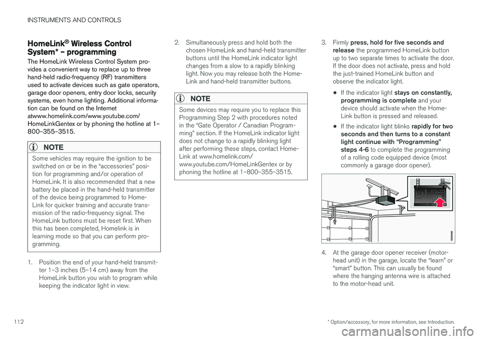
4. At the garage door opener receiver (motor- head unit) in the garage, locate the “learn” or “smart” button. This can usually be foundwhere the hanging antenna wire is attachedto the motor-head unit.
Page 115 of 398
INSTRUMENTS AND CONTROLS
113
5. Firmly press and release the “learn” or
“smart” button. (The name and color of the button may vary by manufacturer.) There are30 seconds to initiate step 6.
6. Return to the vehicle and firmly press, hold for two seconds and release the pro-grammed HomeLink button. Repeat the“press/hold/release” sequence a secondtime, and, depending on the brand of thegarage door opener (or other rolling codeequipped device), repeat this sequence athird time to complete the programmingprocess.
HomeLink should now activate your rolling codeequipped device.
Gate Operator/Canadian Programming
Canadian radio-frequency laws require transmit- ter signals to “time-out” (or quit) after severalseconds of transmission – which may not be longenough for HomeLink to pick up the signal dur-ing programming. Similar to this Canadian law,some U.S. gate operators are designed to “time-out” in the same manner. If you live in Canada or you are having difficulties programming a gate operator or garage dooropener by using the “Programming” procedures, replace “Programming HomeLink” step 2 with the following : •
Continue to press and hold the HomeLink button while you
press and release - every
two seconds (“cycle”) your hand-held trans-
mitter until the HomeLink indicator light changes from a slow to a rapidly blinkinglight. Now you may release both the Home-Link and hand-held transmitter buttons.
Proceed with “Programming” step 3 to complete.
Resetting HomeLink ButtonsUse the following procedure to reset (erase pro-gramming) from the three HomeLink buttons(individual buttons cannot be reset but can be“reprogrammed” as outlined in the following sec-tion):
1. Press and hold the two outer HomeLink but- tons until the indicator light begins to flash.
2. Release both buttons. > HomeLink is now in the training (or learn-ing) mode and can be programmed at any time beginning with “Programming” - step1.
Reprogramming a Single HomeLink Button
To program a device to HomeLink using a Home- Link button previously trained, follow these steps:
1. Press and hold the desired HomeLink but-
ton. DO NOT release the button. 2. The indicator light will begin to flash after 20
seconds. Without releasing the HomeLink button, proceed with “Programming” - step 1.
For questions or comments, contact HomeLinkat: www.homelink.com/www.youtube.com/HomeLinkGentex or by phoning the hotline at 1–800–355–3515. This device complies with FCC rules part 15 and Industry Canada (IC) RSS-210. Operation is sub-ject to the following two conditions: (1) Thisdevice may not cause harmful interference, and(2) This device must accept any interference thatmay be received including interference that maycause undesired operation.
NOTE
The transmitter has been tested and complies with FCC and IC rules. Changes or modifica-tions not expressly approved by the partyresponsible for compliance could void the user
Page 116 of 398
INSTRUMENTS AND CONTROLS
* Option/accessory, for more information, see Introduction.
114
Volvo Sensus
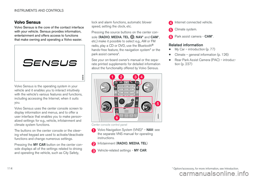
Volvo Sensus is the core of the contact interface with your vehicle. Sensus provides information,entertainment and offers access to functionsthat make owning and operating a Volvo easier.
Volvo Sensus is the operating system in your vehicle and it enables you to interact intuitivelywith the vehicle
Page 117 of 398
INSTRUMENTS AND CONTROLS
* Option/accessory, for more information, see Introduction.115
Information display – menu controls
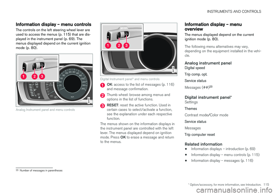
The controls on the left steering wheel lever are used to access the menus (p. 115) that are dis-played in the instrument panel (p. 69). Themenus displayed depend on the current ignitionmode (p. 80).
Analog Instrument panel and menu controls
Digital Instrument panel * and menu controls
OK : access to the list of messages (p. 116)
and message confirmation.
Thumb wheel: browse among menus and options in the list of functions.
RESET : reset the active function. Used in
certain cases to select/activate a function, see the explanation under each respectivefunction.
The menus shown on the information displays inthe instrument panel are controlled with the leftlever. The menus displayed depend on ignition mode. Press OK to erase a message and return
to the menus.
Information display – menu overview
The menus displayed depend on the current ignition mode (p. 80).
The following menu alternatives may vary, depending on the equipment installed in the vehi-cle.
Analog instrument panelDigital speed Trip comp. opt.Service status
Messages (##) 23
Digital instrument panel
*Settings
Themes
Contrast mode /Color mode
Service status
Messages
Trip computer reset
Related information
• Information displays – introduction (p. 69)
• Information display – menu controls (p. 115)
• Information display – messages (p. 116)
23
Number of messages in parentheses
Page 118 of 398
INSTRUMENTS AND CONTROLS
116
Information display – messagesThe controls on the left steering wheel lever are used to scroll among messages displayed in theinstrument panel and to confirm selections. When information, indicator or warning symbols illuminate, an explanatory message will be dis-played in the instrument panel.
When a warning (p. 75), information (p. 73) or indicator symbol (p. 73) comes on, a correspond-ing message appears in the information panel. Anerror message is stored in a memory list until thefault is rectified. Press OK to acknowledge and scroll among the
messages.
NOTE
If a warning message appears while you are using the trip computer, the message must be read and confirmed by pressing OK before
the previous activity can be resumed.
MessageDescription
Stop engineAStop and switch off the engine as soon as possible.Serious risk of damage. Con-tact an authorized Volvoworkshop.
Stop safelyAStop and switch off the engine. Serious risk of dam-age. Contact an authorizedVolvo workshop.
Service urgentAHave the vehicle checked by an authorized Volvo work-shop immediately.
Service requiredAHave the vehicle checked by an authorized Volvo work-shop as soon as possible.
See manualARead the owner's manual.
Book time for mainte-nanceTime to book service at an authorized Volvo retailer.
Time for reg- ular mainte-nanceTime for regular service at an authorized Volvo workshop.The timing is determined bythe number of miles driven,number of months since thelast service, engine runningtime.
MessageDescription
Maintenance overdueIf the service intervals are not followed, the warranty doesnot cover any damaged parts.Contact an authorized Volvoworkshop for service.
Temporarily OFFAA function has been tempo- rarily switched off and isreset automatically while driv-ing or after starting again.
Low battery Power savemodeThe audio system is switched off to save current. Chargethe battery.
A There will also be a system-specific part of this message
Related information
• Information displays – introduction (p. 69)
• Information display – menu overview (p. 115)
• Information display – menu controls (p. 115)
Page 119 of 398
INSTRUMENTS AND CONTROLS
117
Trip computer – introduction
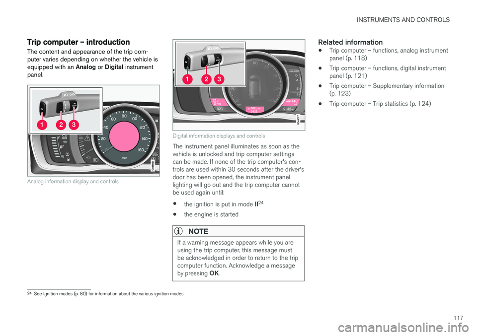
The content and appearance of the trip com- puter varies depending on whether the vehicle isequipped with an Analog or Digital instrument
panel.
Analog information display and controls
Digital information displays and controls
The instrument panel illuminates as soon as the vehicle is unlocked and trip computer settingscan be made. If none of the trip computer's con-trols are used within 30 seconds after the driver'sdoor has been opened, the instrument panellighting will go out and the trip computer cannotbe used again until: • the ignition is put in mode
II24
• the engine is started
NOTE
If a warning message appears while you are using the trip computer, this message mustbe acknowledged in order to return to the tripcomputer function. Acknowledge a message by pressing
OK.
Related information
• Trip computer – functions, analog instrument panel (p. 118)
• Trip computer – functions, digital instrumentpanel (p. 121)
• Trip computer – Supplementary information(p. 123)
• Trip computer – Trip statistics (p. 124)
24
See Ignition modes (p. 80) for information about the various ignition modes.
Page 120 of 398
INSTRUMENTS AND CONTROLS
118
Trip computer – functions, analog instrument panel
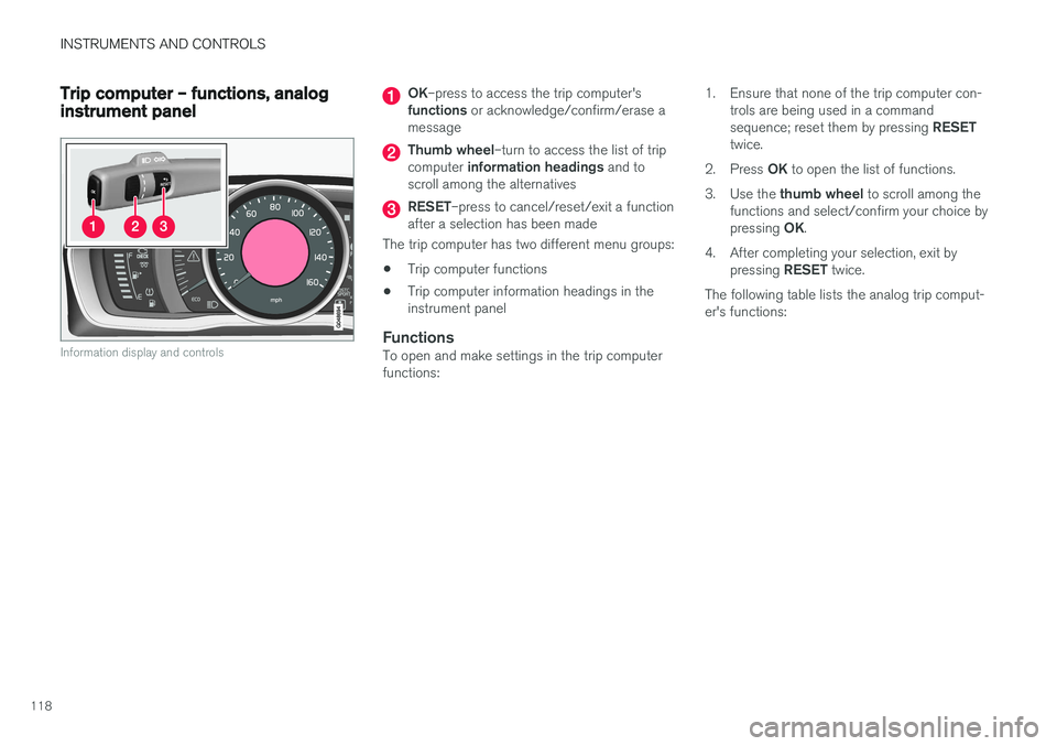
Information display and controls
OK–press to access the trip computer's
functions or acknowledge/confirm/erase a
message
Thumb wheel –turn to access the list of trip
computer information headings and to
scroll among the alternatives
RESET –press to cancel/reset/exit a function
after a selection has been made
The trip computer has two different menu groups: • Trip computer functions
• Trip computer information headings in the instrument panel
FunctionsTo open and make settings in the trip computerfunctions: 1. Ensure that none of the trip computer con-
trols are being used in a command sequence; reset them by pressing RESET
twice.
2. Press OK to open the list of functions.
3. Use the thumb wheel to scroll among the
functions and select/confirm your choice bypressing OK.
4. After completing your selection, exit by pressing RESET twice.
The following table lists the analog trip comput- er's functions: