engine overheat VOLVO XC60 TWIN ENGINE 2019 User Guide
[x] Cancel search | Manufacturer: VOLVO, Model Year: 2019, Model line: XC60 TWIN ENGINE, Model: VOLVO XC60 TWIN ENGINE 2019Pages: 695, PDF Size: 14.96 MB
Page 478 of 695
||
STARTING AND DRIVING
476
the vehicle safely and letting the engine idlefor a few minutes to let the transmissioncool.
If the vehicle begins to overheat, the air con-ditioning may be temporarily switched off.
After a prolonged period of driving indemanding conditions, do not turn off theengine immediately after stopping.
NOTE
It is normal for the engine's cooling fan tooperate for a short time after the engine isswitched off.
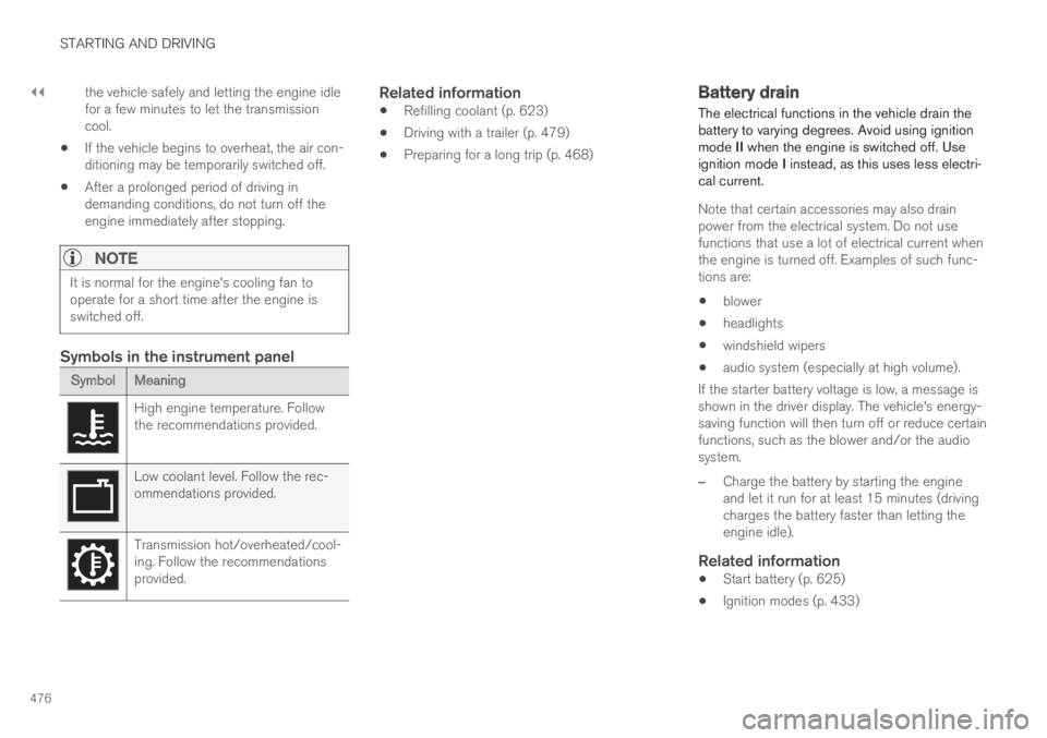
Symbols in the instrument panel
SymbolMeaning
High engine temperature. Followthe recommendations provided.
Low coolant level. Follow the rec-ommendations provided.
Transmission hot/overheated/cool-ing. Follow the recommendationsprovided.
Related information
Refilling coolant (p. 623)
Driving with a trailer (p. 479)
Preparing for a long trip (p. 468)
Battery drain
The electrical functions in the vehicle drain thebattery to varying degrees. Avoid using ignitionmode II when the engine is switched off. Useignition mode I instead, as this uses less electri-cal current.
Note that certain accessories may also drainpower from the electrical system. Do not usefunctions that use a lot of electrical current whenthe engine is turned off. Examples of such func-tions are:
blower
headlights
windshield wipers
audio system (especially at high volume).
If the starter battery voltage is low, a message isshown in the driver display. The vehicle's energy-saving function will then turn off or reduce certainfunctions, such as the blower and/or the audiosystem.
–Charge the battery by starting the engineand let it run for at least 15 minutes (drivingcharges the battery faster than letting theengine idle).
Related information
Start battery (p. 625)
Ignition modes (p. 433)
Page 482 of 695
||
STARTING AND DRIVING
* Option/accessory.480
Follow applicable regulations regarding per-mitted speed and weight.
Drive slowly when towing a trailer up a longand steep incline.
The maximum trailer weights given only applyto altitudes up to 1000 meters (3280 feet)above sea level. At higher altitudes, enginepower (and thus the vehicle's climbing ability)is decreased due to the reduced air density,and the maximum trailer weight must there-fore be reduced. The weight of the vehicleand trailer must be decreased by 10% foreach additional 1000 m (3280 feet) or partthereof.
Avoid driving with a trailer on inclines of morethan 12%.
Avoid overloading and other incorrect use.
The trailer's brakes must be balanced withthe vehicle's brakes to help ensure safestops (follow applicable local regulations).
NOTE
To facilitate towing a trailer in a vehicle equip-ped with pneumatic suspension*, select: the
Suspension ControlDynamic setting inIndividual drive mode.
CAUTION
Bumper-attached trailer hitches must notbe used on Volvos, nor should safetychains be attached to the bumper.
Trailer hitches attaching to the vehiclerear axle must not be used.
Never connect a trailer's hydraulic brakesystem directly to the vehicle brake sys-tem, nor a trailer's lighting system directlyto the vehicle lighting system. Consultyour nearest authorized Volvo retailer forcorrect installation.
When towing a trailer, the trailer's safetychains or wire must be correctly fastenedto the attachment points provided in thetrailer hitch on the vehicle. The safetychain or wire must never be fastened toor wound around the towing ball.
NOTE
The optional detachable trailer hitch may notbe available in all markets or on all models.Consult your Volvo retailer.
NOTE
Extreme weather conditions, towing a trailer,driving at high altitudes and fuel quality arefactors that significantly increase a vehicle'sfuel consumption.
Trailer weights
WARNING
Please adhere to the recommendations provi-ded for trailer weight. If the recommendationsare not followed, the vehicle and trailer maybe difficult to control during evasive maneu-vers and braking.
NOTE
The specified maximum trailer weights arethose permitted by Volvo. National vehicleregulations may set additional restrictions ontrailer weight and speed. The trailer hitchesmay be certified for higher towing weightsthan the vehicle is permitted to tow.
Self-leveling suspension *
The vehicle's self-leveling system attempts tokeep the vehicle at a constant level, regardless ofload (up to the maximum permitted weight).When the vehicle is stationary, the rear end of thevehicle will be slightly lowered, which is normal.
Driving in hilly terrain or hot weather
In certain conditions, there is a risk of overheat-ing when driving with a trailer. If overheating ofthe engine and drive system is detected, a warn-ing symbol will illuminate in the instrument panelalong with a message.
Page 483 of 695
STARTING AND DRIVING
}}
* Option/accessory.481
The automatic transmission selects the optimalgear for the current load and engine speed.
Steep inclines
Do not lock the automatic transmission into ahigher gear than what the engine can handle ‒ itis not always preferable to drive in high gears atlow rpm.
Parking on a hill
1. Depress the brake pedal.
2. Apply the parking brake.
3.Put the gear selector in P.
4. Release the brake pedal.
Put chocks behind the wheels when the vehicleis parked on a hill with a trailer attached.
Starting on a hill
1. Depress the brake pedal.
2.Put the gear selector in D.
3. Release the parking brake.
4. Release the brake pedal and start driving.
Related information
Trailer Stability Assist* (p. 481)
Checking trailer lights (p. 482)
Towing capacity and tongue weight (p. 668)
Overheating of engine and transmission(p. 475)
Trailer Stability Assist*
Trailer Stability Assist (TSA8) is a functiondesigned to help stabilize a vehicle that is tow-ing a trailer when the vehicle and trailer havebegun to sway. The function is part of the Elec-
tronic Stability Control system ESC9.
Reasons for swaying
A vehicle towing a trailer may begin to sway forvarious reasons. Normally this only occurs at highspeeds. However, if the trailer is overloaded orunevenly distributed, e.g. too far back, there is arisk of swaying even at low speeds.
Swaying may be caused by factors such as:
The vehicle and trailer are hit by a sudden,strong crosswind.
The vehicle and trailer are traveling on anuneven road or over a bump.
Sudden movements of the steering wheel.
Once swaying has begun, it can be difficult orimpossible to stop it. This makes the vehicle andtrailer difficult to control and there is a risk ofswerving into oncoming traffic or driving off theroad.
Trailer Stability Assist function
Trailer Stability Assist continuously monitors thevehicle's movements, particularly lateral move-
ments. If swaying is detected, the brakes areapplied individually on the front wheels, which hasa stabilizing effect on the vehicle and trailer. Thisis often enough to enable the driver to regaincontrol of the vehicle.
If the Trailer Stability Assist function's firstattempt is not adequate to stop the swayingmotion, the brakes are applied on all wheels andengine power is temporarily reduced. As theswaying motion begins to decrease and the vehi-cle and trailer have once again become stable,TSA stops regulating the brakes/engine powerand the driver regains control of the vehicle.
NOTE
Trailer Stability Assist is deactivated if thedriver selects the sport mode by deactivatingESC in the center display's menu system.
Trailer Stability Assist may not intervene if thedriver tries to compensate for the swaying motionby moving the steering wheel rapidly, becausethe system will then not be able to determine if itis the trailer or the driver causing the swaying.
8Trailer Stability Assist9Electronic Stability Control
Page 583 of 695

WHEELS AND TIRES
}}
581
3.Make sure the switch is in the 0 (Off) posi-tion and take out the electric cable and thehose.
4.Unscrew the orange cover on the compres-sor and unscrew the cap on the sealing com-pound bottle.
5. Screw the bottle onto the bottle holder as faras possible.
The bottle and the bottle holder are equip-ped with catches to help prevent the sealingcompound from leaking. Once the bottle isscrewed into place into the bottle holder, itcannot be unscrewed. The bottle can only beremoved by a workshop. Volvo recommendsan authorized Volvo workshop.
WARNING
Do not unscrew the bottle. It is equipped witha catch to prevent leakage.
6.Unscrew the tire's valve cap and screw thehose's valve connector as far as possibleonto the valve.
Be sure the air release valve on the com-pressor's hose is completely closed.
7. Connect the electrical cable to the nearest12 V outlet and start the vehicle.
NOTE
Make sure that none of the vehicle's other12 V sockets are used while the compressoris running.
WARNING
Never leave children unattended in the vehiclewhile the engine is running.
WARNING
Inhaling exhaust fumes could lead to seriousinjury. Never leave the engine running in anenclosed space or a space without sufficientventilation.
8.Start the compressor by moving the switch tothe I (On) position.
WARNING
Never stand next to a tire being inflated withthe compressor. If cracks, bulges, etc. form onthe tire, switch off the compressor immedi-ately. The vehicle should not be driven. Callroadside assistance to have the vehicle towedto a workshop for inspection/replacement ofthe tire. Volvo recommends an authorizedworkshop.
NOTE
When the compressor first starts, air pressuremay temporarily increase up to 6 bar (88 psi)but should decrease again after approxi-mately 30 seconds.
9. Inflate the tire for 7 minutes.
CAUTION
To help avoid overheating, the compressorshould never be used for more than10 minutes at a time.
Page 585 of 695
WHEELS AND TIRES
}}
583
The sealing compound bottle must be replacedafter use. Volvo recommends contacting anauthorized Volvo workshop for replacement.
WARNING
After using the tire sealing system, the vehicleshould not be driven farther than approxi-mately 200 km (120 miles).
NOTE
The compressor is an electric device. Followlocal regulations for disposal.
Related information
Recommended tire pressure (p. 565)
Tire sealing system (p. 578)
Inflate tires with the compressor included inthe tire sealing system (p. 583)
Inflate tires with the compressorincluded in the tire sealing system
The vehicle's original tires can be inflated usingthe compressor in the tire sealing system.
1. The compressor must be switched off. Makesure that the switch is in the 0 (Off) positionand take out the electrical cable and thehose.
2.Unscrew the tire's valve cap and screw thehose's valve connector as far as possibleonto the valve.
Be sure the air release valve on the com-pressor's hose is completely closed.
3. Connect the electrical cable to the nearest12 V outlet and start the vehicle.
WARNING
Inhaling exhaust fumes could lead to seriousinjury. Never leave the engine running in anenclosed space or a space without sufficientventilation.
WARNING
Never leave children unattended in the vehiclewhile the engine is running.
4.Start the compressor by moving the switch tothe I (On) position.
CAUTION
Risk of overheating. The compressor shouldnot be running for longer than 10 minutes ata time.
5. Inflate the tire to the pressure specified onthe tire pressure decal on the driver's sidedoor pillar. If the inflation pressure is toohigh, use the air release valve to release air.
6.Switch off the compressor. Remove the hoseand the electrical cable.
7. Screw the valve cap back onto the tire.
NOTE
After inflating a tire, always replace thevalve cap to help prevent valve damagecaused by gravel, dirt, etc.
Use plastic valve caps only. Metal capscould corrode and become difficult toremove.
NOTE
The compressor is an electric device. Followlocal regulations for disposal.
Page 681 of 695
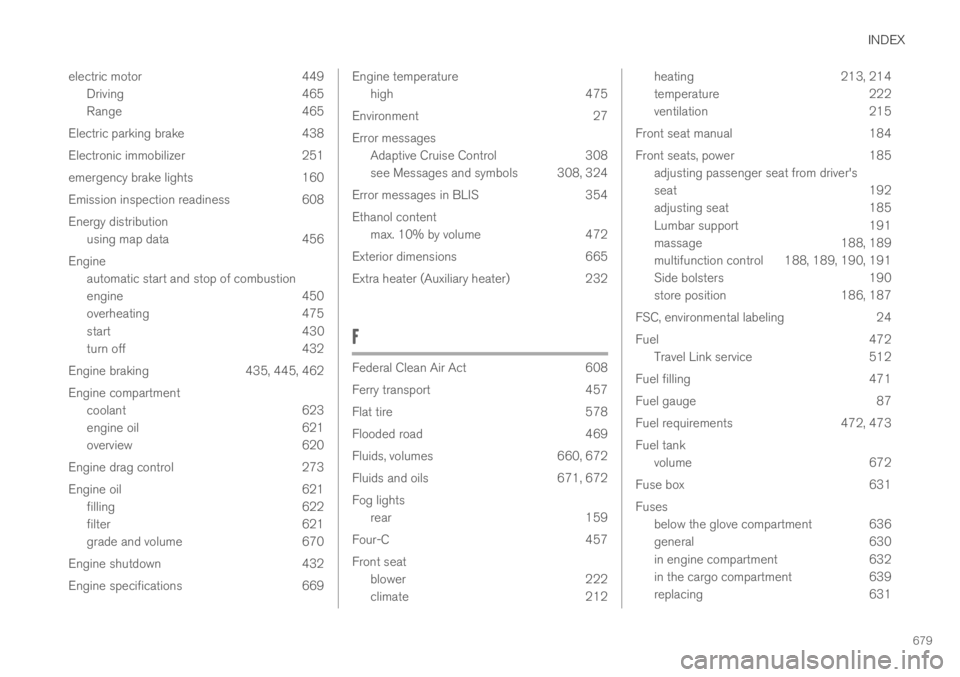
INDEX
679
electric motor 449
Driving 465
Range 465
Electric parking brake 438
Electronic immobilizer 251
emergency brake lights 160
Emission inspection readiness 608
Energy distribution
using map data 456
Engine
automatic start and stop of combustion
engine 450
overheating 475
start 430
turn off 432
Engine braking 435, 445, 462
Engine compartment
coolant 623
engine oil 621
overview 620
Engine drag control 273
Engine oil 621
filling 622
filter 621
grade and volume 670
Engine shutdown 432
Engine specifications 669
Engine temperature
high475
Environment 27
Error messages
Adaptive Cruise Control 308
see Messages and symbols 308, 324
Error messages in BLIS 354
Ethanol content
max. 10% by volume 472
Exterior dimensions 665
Extra heater (Auxiliary heater) 232
F
Federal Clean Air Act608
Ferry transport457
Flat tire 578
Flooded road 469
Fluids, volumes 660, 672
Fluids and oils 671, 672
Fog lights
rear 159
Four-C 457
Front seat
blower 222
climate 212
heating213, 214
temperature222
ventilation 215
Front seat manual 184
Front seats, power 185
adjusting passenger seat from driver's
seat 192
adjusting seat 185
Lumbar support 191
massage 188, 189
multifunction control 188, 189, 190, 191
Side bolsters 190
store position 186, 187
FSC, environmental labeling 24
Fuel 472
Travel Link service 512
Fuel filling 471
Fuel gauge 87
Fuel requirements 472, 473
Fuel tank
volume 672
Fuse box 631
Fuses
below the glove compartment 636
general 630
in engine compartment 632
in the cargo compartment 639
replacing 631
Page 685 of 695
INDEX
683
N
Net
cargo compartment603
O
Occupant safety43
Occupant weight sensor56
Octane rating473
Oil, see also Engine oil670
On-board diagnostics608
On-board Diagnostic socket37
Option/accessory21
Outside temperature gauge94
Overheating475, 479
Owner's information16
OWNER'S MANUAL21
environmental labeling24
in cellular phone20
in the center display17, 18
P
Paddle at steering wheel197
Paint
color code656
paint damage and touch-up 655, 656
Panoramic roof
opening and closing173
pinch protection166
sun shade172, 175
ventilation position174
PAP – Park Assist Pilot 401, 403, 405,
406, 408, 409
Park Assist Camera 391, 392, 394, 396,
398, 399, 400
settings397
Park Assist Camera limitations398
Park Assist Pilot 401, 403, 405, 406,
408, 409
function 401, 403, 406, 408, 409
limitations406
operation403, 405
Symbols and messages409
Park Assist Pilot – PAP 401, 403, 405,
406, 408, 409
parking
on hills440
Parking Assist 385, 386, 387, 388, 389, 390
function385, 386, 387
Parking brake438
activate and deactivate439
automatic activation440
Low battery charge level441
Parking climate224
Symbols and messages231
Parking heater232
Passenger compartment filter205
Passenger compartment heater (Parking
heater)232
Passenger compartment interior 588
center console589
electrical outlet590
glove compartment593
sun visor594
Passenger compartment lighting 162, 163
auto switch162
Passing assistance 303, 304, 320, 321
personal information (Customer Privacy
Policy)35
Phone528
changing to another532
connect529
connect automatically531
connect manually531
delete532