ECU VOLVO XC60 TWIN ENGINE 2020 Owner's Guide
[x] Cancel search | Manufacturer: VOLVO, Model Year: 2020, Model line: XC60 TWIN ENGINE, Model: VOLVO XC60 TWIN ENGINE 2020Pages: 687, PDF Size: 14.65 MB
Page 432 of 687

STARTING AND DRIVING
* Option/accessory.
430
Leveling control * and suspension
The vehicle's leveling control system adjusts the suspension and shock absorbers auto-matically to help optimize comfort and con-trol while driving. Leveling can also be con-trolled manually to facilitate loading or get-ting in and out of the vehicle.
Manually adjustable shock absorbers *The suspension on Polestar Engineered* vehi-
cles can be manually adjusted. There are three recommended modes: Performance,engineered and Comfort.
Performance mode
In Performance mode, the vehicle's suspen- sion feels stiffer.
Engineered, factory setting
Engineered is designed for daily driving.
Comfort mode
In Comfort mode, the vehicle's suspension feels softer.
Pneumatic suspension and shock
absorbers
The system is adapted to the selected drivemode and vehicle speed. The pneumatic sus- pension reduces the vehicle's ground clear-ance at higher speeds to reduce air resistanceand increase stability. The shock absorbers arenormally set to help optimize comfort and areadjusted continuously according to the roadsurface and the vehicle's acceleration, brakingand cornering.
The instrument panel indi-cates when the suspensionlevel is being adjusted.
The following apply if a door or the tailgate is opened: If a door is opened, the level can only be adjusted upwards.
If the tailgate is open, the level can only beadjusted downwards.
ParkingWhen parking, make sure that there is ade-quate space above and below the vehiclesince ground clearance may vary dependingon e.g. ambient temperature, how the vehicle is loaded, if loading mode is used, which drivemode is selected after the engine is started,etc. The level may also be adjusted a period after the vehicle is parked. This is to compensatefor any height changes that may occur due totemperature changes in the air springs whenthe vehicle cools.
TransportingWhen transporting the vehicle on a ferry, trainor truck, only secure (lash) the vehicle aroundthe tires, not using any other parts of the chas-sis. Changes in the pneumatic suspensionmay occur during transport, which couldadversely affect the lashing and result in dam-age.
Page 454 of 687

||
STARTING AND DRIVING
4521. Put the ignition in mode
0.
2. Make sure the auxiliary battery (the bat- tery used to jump start the discharged battery) has a voltage of 12 volts.
3. If the auxiliary battery is in another vehicle, turn off that vehicle's engine and makesure that the vehicles are not touchingeach other.
4. Clamp the red jumper cable onto the auxil- iary battery's positive (+) terminal (1).
CAUTION
Connect the jump cable carefully to pre- vent short circuits with other componentsin the engine compartment.
5. Fold back the cover over your vehicle's positive (+) jump start terminal (2).
6. Clamp the other end of the red jumper cable to your vehicle's positive (+) jump start terminal (2).
7. Clamp the black jumper cable onto the auxiliary battery's negative (-) terminal (3).
8. Clamp the other end of the black jumper cable to your vehicle's negative (-) groundpoint (4). 9. Make sure the jumper cables are securely
attached to help prevent sparks whilejump starting.
10. Start the engine of the assisting vehicle and let it run for a few minutes at a higheridling speed than normal, about1500 rpm.
11. Start your vehicle's engine. If the engine does not start, allow an additional 10minutes of charging time and then try tostart the engine again.
NOTE
When the engine is started under normal conditions, the vehicle's electrical drivemotor is prioritized – the gasoline engineremains off. This means that after the startknob has been turned clockwise, the elec-tric motor has "started" and the vehicle isready to be driven. Start of the electricmotor is indicated by the indicator lights onthe instrument panel going out and its pre-selected theme illuminating.
CAUTION
Do not touch the connections between the cable and the vehicle during the startattempt. Risk of sparking.
12. Remove the jumper cables in the reverseorder ‒ first the black cables and then the
red cables. Make sure that none of the clamps of the black jumper cables come into contactwith either vehicle's positive (+) jump startterminals or either of the red jumpercable's connected clamps.
WARNING
PROPOSITION 65 WARNING! Battery
posts, terminals, and related accessories contain lead and lead compounds, chemi-cals known to the state of California tocause cancer and reproductive harm. Washhands after handling.
WARNING
Batteries generate hydrogen gas, which is flammable and explosive.
Do not connect the jumper cable toany part of the fuel system or to anymoving parts. Avoid touching hotmanifolds.
Battery fluid contains sulfuric acid. Donot allow battery fluid to contact eyes,skin, fabrics or painted surfaces.
If contact occurs, flush the affectedarea immediately with water. Obtain
Page 456 of 687

||
STARTING AND DRIVING
454
Retracting the hitch1. Open the tailgate. Press the button on therear, right-hand side of the cargo compart- ment and release. Pressing too long onthe button may prevent the hitch fromfolding in.
> The hitch will automatically fold downto the unlocked position and the indica- tor light in the button will flash orange. 2.
Secure the hitch into position by pushing it back to its retracted position under thebumper, where it will lock into place.
> The indicator light in the button will
now glow steadily if the hitch is cor- rectly locked in the retracted position.
CAUTION
Make sure that there is no adapter in the electrical socket or removable ball sectionmounted when the towbar is folded in. Remove the bicycle holder from the towbar when it is not being used.
Hitch-mounted bicycle holder
NOTE
The weight limits for trailers and towbar- mounted accessories differ. A separatelimit applies for each. This towbar is onlydesigned for towbar-mounted bicycle hold-ers. All other accessories are not suitable.
Before mounting the bicycle on the bicycle holder, keep in mind that:
The maximum weight for the bicycleholder including bicycles is 130 lbs/60 kg.For example: holder 40 lbs + bicycle 30lbs + bicycle 30 lbs = 100 lbs total > OK
Do not mount more than two bicycles
The center of gravity should not exceed thedimensions:
1. 613 mm (24 1/7 ")
2. 642 mm (25 2/7 ")
Page 457 of 687

STARTING AND DRIVING
}}
* Option/accessory.455
NOTE
Volvo recommends only using Volvo origi- nal accessories. Follow the instructionssupplied with the product.
CAUTION
Never use towbar adapters or towbar extenders
Only use ball mount for towing. Do notmount accessories directly on the ballmount. Use accessories designed tobe mounted in the towbar's squarebracket. Do not use accessoriesdesigned to be secured around the ballmount.
Loading the bicycle holderThe greater the distance between the load and the bicycle holder, the greater the load on thehitch and on the vehicle. Keep the following points in mind: Mount the heaviest bicycle closest to the vehicle.
If possible, mount the bicycles symmetri-cally, as close as possible to the center ofthe vehicle.
Remove loose objects from the bicycle,such as baskets, batteries or child seats.This will help reduce the load on the hitchand the bicycle holder.
Do not place a cover over the bicycle asthis could lead to increased load on thehitch.
Related information
Detachable towbar
* (p. 455)
Driving with a trailer (p. 457)
Detachable towbar
*
Volvo recommends the use of Volvo towbars that are specially designed for the vehicle.
NOTE
The optional detachable trailer hitch may not be available in all markets or on allmodels. Consult your Volvo retailer.
Ball holder
Cotter pin
Towbar assembly
Locking bolt
Safety wire attachment bracket
Page 458 of 687

||
STARTING AND DRIVING
* Option/accessory.
456
Installing the ball holder1. If necessary, remove the cotter pin from
the locking bolt and slide the locking bolt out of the towbar assembly.
2. Slide the ball holder into the towbar assembly.
3. Align the hole in the ball holder with the one in the towbar assembly.
4. Slide the locking bolt through the towbar assembly/ball holder.
5. Insert the cotter pin in the hole at the end of the locking bolt.
WARNING
Be sure the towbar is securely locked in position before attaching anything toit.
Always attach the trailer's safety wiresecurely to the towbar's safety wireattachment bracket.
Removing the ball holder1. Remove the cotter pin from the locking
bolt and slide the locking bolt out of theball holder/towbar assembly.
2. Pull the ball holder out of the towbar assembly.
WARNING
Damage may occur on the towbar if it is not used correctly or if incorrect or faultyaccessories are used, such as:
Overloading of accessory.
Use of incorrect or faulty accessory.
Accessory used for an incorrect pur- pose.
Use of weight-distributing towing sys-tem.
Incorrectly positioned ball mount; seegeometric limits for the towbar.
Stowing the ball holder
WARNING
When not in use, the detachable ball holder should always be properly stowed in thedesignated location under the floor of thecargo compartment.
Driving with a trailerWhen towing a trailer, the original ball holder or equivalent should be used.
The ball mount must fall within the geometric limits for the towbar, for both distance
and
height
. Geometric limits are described on a
type plate located on the towbar.
Related information
Retractable hitch
* (p. 453)
Driving with a trailer (p. 457)
Towing capacity and tongue weight (p. 660)
Page 463 of 687

STARTING AND DRIVING
}}
461
Towing using a towline
This section refers to one vehicle being towed behind another using a towline.
Never attempt to tow a Twin Engine vehicle behind another vehicle as this could damagethe electric motor. The vehicle must instead belifted onto a tow truck and transported with allfour wheels on the bed or lifting platform ofthe truck (no wheels may touch the road).
Towing another vehicleTowing another vehicle requires a lot of power - use the Constant AWD drive mode. This
helps charge the hybrid battery and improve the vehicle's driving and roadholding characte-ristics. Before towing another vehicle, check applica- ble speed limit regulations.
Jump startingNever attempt to tow the vehicle to start theengine, as this could damage the electricmotor. Use an auxiliary battery if the start bat-tery's charge level is so low that the enginecannot be started.
CAUTION
Attempts to tow-start the vehicle could cause damage to the electrical drive motorand three-way catalytic converter.
Related information
Attaching and removing the towing eyelet (p. 461)
Hazard warning flashers (p. 164)
Recovery (p. 462)
Jump starting using another battery(p. 451)
Selecting ignition mode (p. 406)
Transmission (p. 416)
Attaching and removing the towing eyelet
Use the towing eyelet to tow another vehicle. Screw the towing eyelet securely into placein the threaded outlet behind the cover on theright-hand side of the rear bumper.
NOTE
If the vehicle is equipped with a towbar, there is no rear attachment for the towingeye.
Attaching the towing eyelet
Take out the towing eyelet, which is stored in a foam block under the floor inthe cargo compartment.
Page 464 of 687

||
STARTING AND DRIVING
* Option/accessory.
462
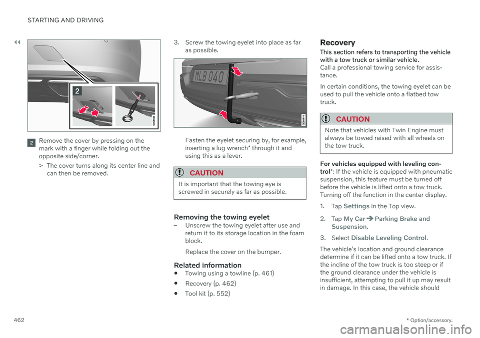
Remove the cover by pressing on the mark with a finger while folding out theopposite side/corner.
> The cover turns along its center line and
can then be removed. 3. Screw the towing eyelet into place as far
as possible.Fasten the eyelet securing by, for example, inserting a lug wrench * through it and
using this as a lever.
CAUTION
It is important that the towing eye is screwed in securely as far as possible.
Removing the towing eyelet–Unscrew the towing eyelet after use and return it to its storage location in the foamblock. Replace the cover on the bumper.
Related information
Towing using a towline (p. 461)
Recovery (p. 462)
Tool kit (p. 552)
Recovery
This section refers to transporting the vehicle with a tow truck or similar vehicle.
Call a professional towing service for assis- tance. In certain conditions, the towing eyelet can be used to pull the vehicle onto a flatbed towtruck.
CAUTION
Note that vehicles with Twin Engine must always be towed raised with all wheels onthe tow truck.
For vehicles equipped with leveling con- trol *: If the vehicle is equipped with pneumatic
suspension, this feature must be turned off before the vehicle is lifted onto a tow truck.Turning off the function in the center display. 1. Tap
Settings in the Top view.
2. Tap
My CarParking Brake and
Suspension.
3. Select
Disable Leveling Control.
The vehicle's location and ground clearance determine if it can be lifted onto a tow truck. Ifthe incline of the tow truck is too steep or ifthe ground clearance under the vehicle isinsufficient, attempting to pull it up may resultin damage. In this case, the vehicle should
Page 466 of 687

STARTING AND DRIVING
* Option/accessory.
464
Programming HomeLink ®
*20
Follow these instructions to program HomeLink ®
, reset all programming, or pro-
gram individual buttons.
NOTE
In some vehicles, the ignition must be on or in the "accessory position" before HomeLink ®
can be programmed or used. It
can be a good idea to put new batteries in the remote control being replaced by HomeLink ®
for faster programming and
better radio signal transmission. TheHomeLink ®
buttons should be reset before
programming.
WARNING
While HomeLink ®
is being programmed,
the garage door or gate being programmed may be activated. Make sure that no one isnear the door or gate during programming.When programming a garage door opener,it is advised to park outside of the garage. 1. Point the remote control at the
HomeLink ®
button to be programmed and
hold it about 2-8 cm (1-3 inches) from the button. Do not obstruct the HomeLink ®
indicator light. Note: Some remote controls are more
effective at programming HomeLink ®
from
a distance of about 15-20 cm (6-12 inches). Keep this in mind if you experi-ence any programming difficulties.
2. Press and hold both the remote control button and the HomeLink ®
button to be
programmed. 3. Do not release the buttons until the indica-
tor light has stopped flashing slowly(about once a second) and either flashesquickly (about 10 times a second) orglows steadily. >If the indicator light glows steadily: Indication that programming is com-plete. Press the programmed buttontwice to activate. If the indicator light flashes quickly: The device being programmed with HomeLink ®
may have a security func-
tion that requires an extra step. Try pressing the programmed button twiceto see whether the programmingworks. Otherwise, continue with thefollowing steps.
20 Certain markets only.
Page 470 of 687

STARTING AND DRIVING
* Option/accessory.
468
Calibrating the compass *
The globe is divided into 15 magnetic zones. The compass 27
should be calibrated if the
vehicle is driven from one zone to another.
1. Stop the vehicle in a large, open area away from steel constructions and high-voltage power lines.
2. Start the engine and switch off all electri- cal equipment (climate system, wipers,etc.) and make sure all doors are closed.
NOTE
Calibration may fail or not even be initiated if electrical equipment is not turned off.
3. Hold the button on the bottom of the rear-view mirror pressed for about 3 seconds (using e.g. a paper clip). The number of thecurrent magnetic zone is shown.
15
14
13
12
11
9
8
7
6
5
4
3
2
1
10
Magnetic zones.
4. Press the button on the underside of themirror repeatedly until the desired mag- netic zone (
1–15) appears (see the map of
magnetic zones).
5. Wait until the display again shows
C, or
press and hold the button on the under- side of the rearview mirror for approx.
6 seconds until
C is displayed.
6. Drive slowly in a circle at a speed of no more than 10 km/h (6 mph) until a com- pass direction is shown in the display. Thisindicates that calibration is complete.Drive in a circle two more times to fine-tune the calibration. 7.
Vehicles with heated windshields *: If
Cis shown in the display when the wind- shield heating function is activated, per-form step 6 above with the heating func-tion on.
8. Repeat the above procedure as needed.
Related information
Compass
* (p. 467)
Activating and deactivating the compass
*
(p. 467)
27 Rearview mirror with compass is available as an option only on certain markets and models.
Page 518 of 687

AUDIO, MEDIA AND INTERNET
* Option/accessory.
516
Internet-connected vehicle *
When the vehicle is connected to the Inter- net, it is possible to use web radio and musicservices via apps, download software andcontact retailers from the vehicle.
The vehicle can be connected to the Internet using Bluetooth, Wi-Fi or the vehicle's inte-grated modem (SIM card). When the vehicle is connected to the Internet, it is possible to share the vehicle's Internetconnection (Wi-Fi hotspot) so that other devi- ces, e.g. tablets, can access the Internet 12
.
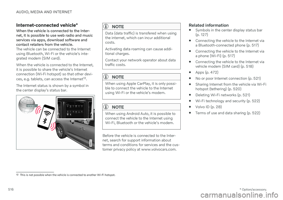
The Internet status is shown by a symbol in the center display's status bar.
NOTE
Data (data traffic) is transfered when using the internet, which can incur additionalcosts. Activating data roaming can cause addi- tional charges. Contact your network operator about data traffic costs.
NOTE
When using Apple CarPlay, it is only possi- ble to connect the vehicle to the Internetusing Wi-Fi or the vehicle's modem.
NOTE
When using Android Auto, it is possible to connect the vehicle to the Internet usingWi-Fi, Bluetooth or the vehicle's modem.
Before the vehicle is connected to the Inter- net, search for support information aboutterms and conditions for services and the cus-tomer privacy policy at www.volvocars.com.
Related information
Symbols in the center display status bar(p. 127)
Connecting the vehicle to the Internet viaa Bluetooth-connected phone (p. 517)
Connecting the vehicle to the Internet viaa phone (Wi-Fi) (p. 517)
Connecting the vehicle to the Internet viavehicle modem (SIM card) (p. 518)
Apps (p. 472)
No or poor Internet connection (p. 521)
Sharing Internet from the vehicle via Wi-Fihotspot (tethering) (p. 520)
Deleting Wi-Fi networks (p. 521)
Wi-Fi technology and security (p. 522)
Volvo ID (p. 28)
Terms of use and data sharing (p. 522)
12
This is not possible when the vehicle is connected to another Wi-Fi hotspot.