fuse box VOLVO XC70 2004 Owners Manual
[x] Cancel search | Manufacturer: VOLVO, Model Year: 2004, Model line: XC70, Model: VOLVO XC70 2004Pages: 241, PDF Size: 5.78 MB
Page 133 of 241

2004 VOLVO XC70
l First connect the auxiliary battery positive (+) terminal (1) to the\
positive (+) terminal in your car's
engine compartment (2), located under a small black plastic cover atta\
ched to the fuse box cover,
marked with a "+" sign. Remove the cover on the main fuse box if necessa\
ry to access this terminal. See
page 119.
l Then connect the auxiliary battery negative (-) terminal (3) to the \
ground point in your car's engine
compartment (4).
Start the engine in the assisting car, then start the engine in the car \
with the dead battery.
l After the engine has started, first remove the negative (-) terminal j\
umper cable. Then remove the
positive (+) terminal jumper cable.
CAUTION:
Improper hookup of jumper cables or use of other than 12-volt batteries \
could result in damage to
equipment and/or the battery.
WARNING!
l Do not connect the jumper cable to any part of the fuel system or to any\
moving parts. Avoid
touching hot manifolds.
l Never expose the battery to open flame or electric spark.
l Do not smoke near the battery.
l Batteries generate hydrogen gas which is flammable and explosive.
l Battery fluid contains sulfuric acid. Do not allow battery fluid to cont\
act eyes, skin, fabrics or
painted surfaces. If contact occurs, flush the affected area immediately\
with water. Obtain medical
help immediately if eyes are affected.
Failure to follow the instructions for jump starting can lead to persona\
l injury.
NOTE: Refer to
pages 140-141 for information on properly maintaining the battery.
PROPOSITION 65 WARNING!
Battery posts, terminals, and related accessories contain lead and lead \
compounds, chemicals known
to the state of California to cause cancer and reproductive harm. Wash h\
ands after handling.
pg. 105 Winter driving
file:///K|/ownersdocs/2004/2004_XC70/04xc70_06b.htm (7 of 10)12/30/200\
6 4:33:02 PM
Page 149 of 241

2004 VOLVO XC70
pg. 118 Fuses
Replacing fuses
If an electrical component fails to function, it is possible that a fuse\
has blown due to a temporary circuit
overload.
Fuses are located in different places:
A - Relays/fuse box in the engine compartment
B - Fuse box in the passenger compartment
C - Relays/fuse box in the cargo area
A label on the inside of each cover indicates the amperage and the elect\
rical components that are
connected to each fuse.
The easiest way to see if a fuse is blown is to remove it. Pull the fuse\
straight out. If a fuse is difficult to
remove, you will find a special fuse removal tool in the passenger compa\
rtment fuse box. From the side,
examine the curved metal wire to see if it is broken. If so, put in a ne\
w fuse of the same color and
amperage (written on the fuse). Spare fuses are stored in the fuse box in the \
passenger compartment. If
fuses burn out repeatedly, have the electrical system inspected by an au\
thorized Volvo retailer.
WARNING!
Never use fuses with higher amperage that those stated on the following \
pages. Doing so could
overload the car's electrical system.
file:///K|/ownersdocs/2004/2004_XC70/04xc70_08a.htm (2 of 22)12/30/200\
6 4:33:05 PM
Page 150 of 241

2004 VOLVO XC70
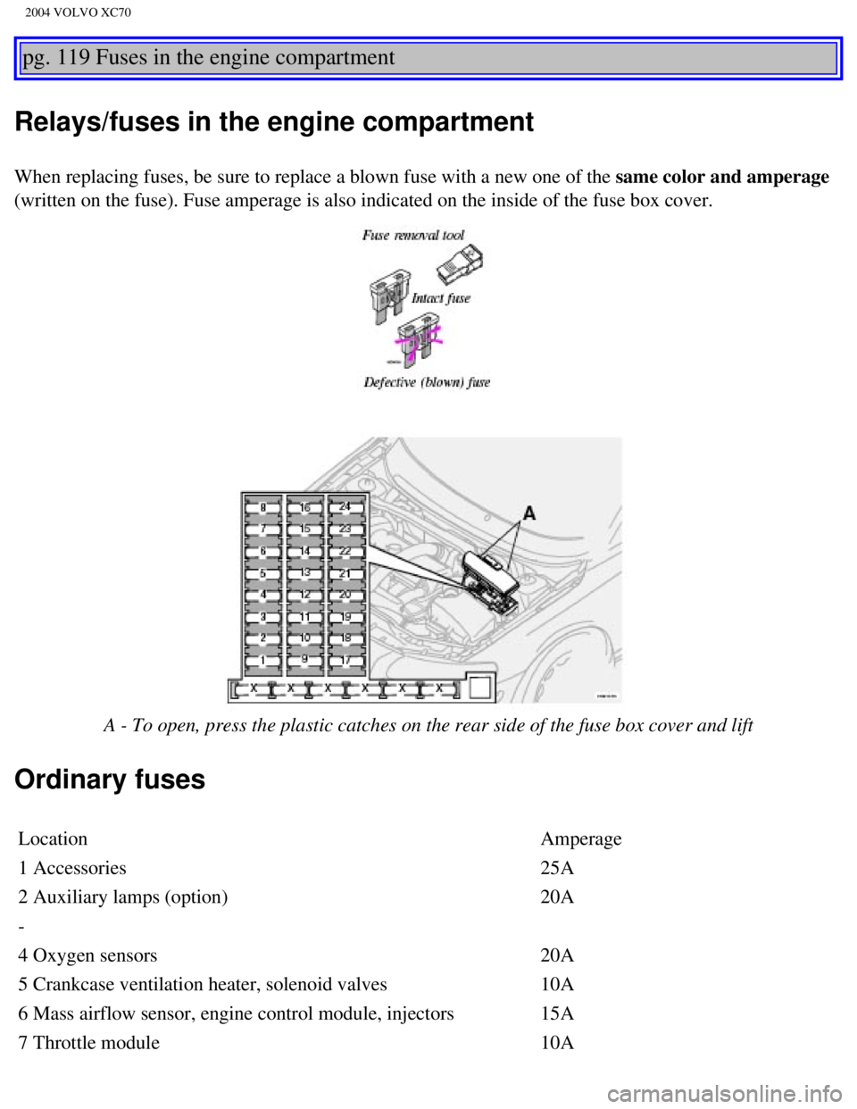
pg. 119 Fuses in the engine compartment
Relays/fuses in the engine compartment
When replacing fuses, be sure to replace a blown fuse with a new one of \
the same color and amperage
(written on the fuse). Fuse amperage is also indicated on the inside o\
f the fuse box cover.
A - To open, press the plastic catches on the rear side of the fuse box \
cover and lift
Ordinary fuses
Location Amperage
1 Accessories 25A
2 Auxiliary lamps (option) 20A
-
4 Oxygen sensors 20A
5 Crankcase ventilation heater, solenoid valves 10A
6 Mass airflow sensor, engine control module, injectors 15A
7 Throttle module 10A
file:///K|/ownersdocs/2004/2004_XC70/04xc70_08a.htm (3 of 22)12/30/200\
6 4:33:05 PM
Page 151 of 241

2004 VOLVO XC70
8 A/C compressor, accelerator pedal position sensor, E-box fan 10A
9 Horn 15A
10 Tailgate wiper 10A
11 Ignition coils 20A
12 Brake light switch 5A
13 Windshield wipers 25A
14 ABS/STC/DSTC 30A
15 -
16 Windshield washers, headlight wiper/washers (certain
models) 15A
17 Low beam, right 10A
18 Low beam, left 10A
19 ABS/STC/DSTC 30A
20 High beam, left 15A
21 High beam, right 15A
22 Starter motor 25A
23 Engine control module 5A
24 -
pg. 120 Fuses in the passenger compartment
Fuse box in the passenger compartment
This fuse box is located at the far left side of the instrument panel. E\
xtra fuses and the fuse removal tool
are also stored here. When replacing a blown fuse, be sure to replace it\
with a new one of the same color
and amperage (written on the fuse).
file:///K|/ownersdocs/2004/2004_XC70/04xc70_08a.htm (4 of 22)12/30/200\
6 4:33:05 PM
Page 176 of 241

2004 VOLVO XC70
Engine compartment
1 Expansion tank - coolant
2 Power steering fluid reservoir
3 Washer fluid reservoir
4 Dipstick - engine oil
5 Radiator/cooling fan
6 Oil filler cap - engine
7 Brake fluid reservoir
8 Relay/fuse box
9 Air cleaner
10 Battery (in the cargo compartment) WARNING!
The cooling fan may start or continue to operate (for up to 6 minutes)\
after the engine has been
switched off.
pg. 137 Engine oil
Oil quality
Engine oil must meet the minimum ILSAC specification GF-2, including ACE\
A A1, API SJ, SJ/CF and
SJ/Energy Conserving.
Your Volvo has been certified to standards using ILSAC oil specification\
GF-2 5W-30. Volvo
file:///K|/ownersdocs/2004/2004_XC70/04xc70_08b.htm (7 of 16)12/30/200\
6 4:33:06 PM